*e-mail: [email protected]
1. Introduction
It is known that CO2 corrosion is the predominant form of corrosion found in the oil and natural gas industry1. This is generally because of the crude oil and natural gas from the oil reservoir/gas well usually contains some level of CO2. The extraction of the oil and gas in deep reservoir, the pre-salt, bring major challenges to industry that besides other peculiarities, presenting a high level of contamination with CO2. However, the evaluation of the corrosion mechanism is performed in stagnant solutions and so the hydrodynamic factors are ignored.
The intensity and the corrosion mechanism on the internal wall of a pipelines are strongly dependent on surface phenomena which include the interactions of the pipeline wall with the electrolyte low. There is a wide variety of models for understanding the CO2 corrosion of carbon steel2,3,4,5,6,7. It is known that the CO2 effect is associated with the increased amount of hydrogen developed in the cathode and with the formation of an iron carbonate ilm as a corrosion product on the steel surface. Many of the CO2 corrosion models associated with electrolyte low are no longer empirical and are described by computational methods8 .
The currently accepted CO2 corrosion mechanism involves the hydration of CO2 and formation of H2CO3. The cathodic reaction that describes this process is given by:
CO2 + H2O ↔ H2CO3 (1)
This reaction takes place in a solution as follows:
H2CO3 ↔ H+ + HCO 3
– (2)
HCO3– ↔ H+ + CO 3
2– (3)
The anodic reaction initially involves iron oxidation on the electrode surface and its dissolution in the following steps:
Fe + OH–→ FeOH + e– (4)
FeOH → FeOH+ + e– (5)
FeOH+ → Fe2+ + OH– (6)
When the salt solubility is exceeded, the iron carbonate ilm precipitates on the steel surface.
Fe2+ + CO 3
2– → FeCO
3 (7)
The aqueous corrosion of carbon steel by CO2 is an electrochemical process that involves the anodic dissolution of steel and the cathodic hydrogen evolution9. The overall reaction is:
Fe + CO2 + H2O → FeCO3 + H2 (8)
The precipitation process on the steel surface can be control the corrosion processes. Depending on experimental conditions, the FeCO3 forming a unifom layer and the corrosion rate decrease due to the presence of a diffusion barrier for the species involved in the corrosion process and the covering and protection of a portion of the steel surface10.
The hydrodynamic behavior of the luid can change the FeCO3 precipitation and the corrosion rate. Since corrosion is a surface phenomenon, the luid dynamics that deines the electrolyte’s interactions with the surface is a determining factor in the corrosion processes. The structure of the hydrodynamic boundary layer changes with the increase in the velocity of the luid and the roughness of the steel surface11. Therefore the study of the changes in the boundary
CO
2Corrosion in the Region Between the Static and Turbulent Flow Regimes
Lilian Raquel Moretto Ferreiraa*, Haroldo Araujo Ponteb, Luciana Schmidlin Sanchesb,
Ana Carolina Tedeschi Gomes Abrantesb
aCentro Universitário Tupy – UNISOCIESC, Joinville, SC, Brazil
bLaboratório de Eletroquímica de Superfícies e Corrosão, Universidade Federal do Paraná – UFPR, Curitiba, PR, Brazil
Received: March 9, 2014; Revised: March 4, 2015
This paper discusses the inluence of the low of a luid from the static regime to the turbulent in CO2 corrosion experienced by low carbon steel. A more comprehensive approach to CO2 corrosion implies taking the free lowing velocity and shear stress of the luid and the surface roughness of the material into consideration. Low carbon steel samples in two different supericial inish conditions were used as the rotating cylinder electrode. The corrosion rate were determined by linear polarization at 25 °C in a 0.5 mol/L NaHCO3 solution purged with CO2 at 1 atm pressure in pH 7.5. The effect of supericial inish on CO2 corrosion in low conditions was studied. The results obtained showed that the corrosion rate increases with low velocity and is inluenced by surface roughness.
layer is very important to deine the mechanism of the corrosion product formation and its behavior in relation to the moving luid.
Knowledge of the relationship between low and CO2 corrosion has become an emerging need for the oil industry and although more than four decades of research have past, the understanding of CO2 corrosion remains incomplete. The inluence of the luid shear stress on the laminar to turbulent low transition is still not well understood.
2. Experimental Procedures
A rotating cylinder electrode and electrochemical techniques were used to evaluate the behavior of low carbon steel with CO2 corrosion and its correlation with the luid low on the metallic surface. The conventional 3-electrode electrochemical cell consisted of a glass body with approximate capacity 100 ml, model RDE0010, EG&G Princeton Applied Research. Besides the reference (saturated calomelane) and auxiliary (spiral platinum) working electrodes, a carbon dioxide (CO2) bubble was attached to the glass cell. A model PGZ 100 VoltaLab 10 Radiometer Analytical potentiostat controlled by the VoltaMaster 4 software was used to perform the experiment and obtain all the electrochemical measurement data.
The electrolyte used was a deaired 0.5 mol/L sodium bicarbonate (NaHCO3) solution saturated with CO2 by CO2 bubble for 30 minutes with pH = 7.5 stabilized at room temperature. Bubbling was performed while preparing the solution for the tests and during the tests to maintain a CO2 -rich atmosphere over the electrolyte. The corrosion rates were measured electrochemically using Linear Polarization Resistence (LPR) technique. The carbon steel working electrode was polarized at ± 20 mV and the scan rate was 0.2 mV/s. The corrosion rate was calculated by using cathodic Tafel slope of 120 mV/dec and anodic Tafel slope of 40 mV/dec.
The working electrodes consisted of AISI 1020 steel cylinders with 12.50 mm external diameter and 8.00 mm height. Before each electrochemical measurement series, a different working electrode was smoothed with a 1200 grain sandpaper to remove any supericial oxides.
To verify the inluence of supericial roughness in the corrosion rates, some electrodes were submitted to blasting with stainless steel spherical geometry grit in a ROTOMAC machine with 0.71 mm mesh opening. That way, there are two groups of samples: standard (without blasting) and blasted. The surface roughness was determined with Confocal Microscopy (LEXT 3D – OLS 4000). The surface characterization was made by Scanning Electron Microscope with Energy Dispersive Spectroscopy (JEOL JSM– 6390LV).
2.1. Hydrodynamic behaviour
The corrosion is a surface phenomenon, in this way the luid dynamics that deines the electrolyte’s interactions with the surface is a determining factor in the corrosion processes. In 1904 Prandtl12 proposed the concept of boundary layers. He showed that many outlows can be analyzed dividing them into two regions, one close to the pipeline and the other covering the remaining outlow. The narrow region adjacent to a solid border is called the boundary layer, in which the effect of viscosity is important. In the region outside the boundary layer, the effect of viscosity is negligible and the luid can be considered non-viscous12.
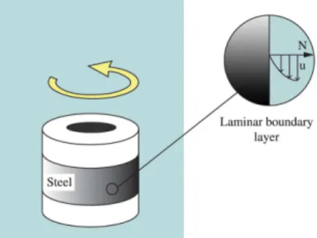
Since every luid presents viscosity, experimental observation shows that when a luid lows parallel to a stationary solid surface (metallic wall) the luid molecules in contact with the surface adhere to the surface and so its velocity is zero. The adjacent luid layers experience a braking effect shown by the velocity vector u in the boundary layer created on the surface of the moving electrode (see Figure 1). Considering that the luid as a whole is moving, velocity gradients and shear stresses must be present in the outlow. In turn, these shear stresses affect the luid’s motion and interfere in the iron carbonate layer formation mechanism.
Reynolds number (Re) is a parameter to establish the type of velocity boundary layer that develops on the electrode surface. According to Fox et al.12, Reynolds number gives an effective measurement of the features of the luid in the system is question and is given by the equation below:
du Re=
ν (9)
Where:
d = cylinder diameter (m)
u = supericial velocity of the cylinder (m/s) ν = kinematic viscosity of the luid (m2/s)
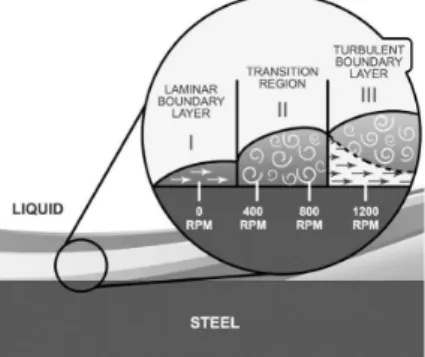
The transition region between the laminar and the turbulent lows occurs at 2000<Re<2400, where there is formation of Taylor vortices in the space between the electrodes, so operating in the transition regime is not recommended for electrochemical studies. For Re>2400, totally turbulent low is maintained and mass transportation is substantially increased with increased rotation rate. Thus, for comparative purposes, the rotation rates in this study were established at 400 rpm, 800 rpm and 1200 rpm, because it is known that the geometry of the experimental device allows Re>2400, which characterizes the turbulent low regime as shown in Figure 2.
According to the works cited by Silverman13 and to norm ASTM G18514, it is accepted that the shear stress on the cylinder wall be given by the equation below:
2
f u 2
τ = ρ (10)
Where:
ρ = speciic mass of the luid (kg/m3) u = supericial velocity of the cylinder (m/s) f = friction factor (dimensionless)
Figure 1. Schematic hydrodynamic boundary layer that develops
The friction factor is mathematically determined by the equation below, considering the experimental measurements before each electrochemical experiment for the average roughness on the cylinder surface. Thus,
0.39 0.2
f d
o.714(Re) ( )
2
− −
=
ε (11)
Where:
Re = Reynolds number (dimensionless) d = cylinder diameter (m)
ε = supericial roughness (m) obtained from the Ra parameter In accordance with the experimental planning, the intention is to change the shear stress of the luid by varying the roughness ε of the electrode.
3. Results and Discussion
The picture in Figure 3 shows the top view of ferrous carbonate layer formed in the standard sample from stagnant condition, at 25 °C in a 0.5 M NaHCO3 solution purged with CO2 and pH 7.5. The EDS analysis shows the presence of carbon, oxygen and iron, conirming the presence of FeCO3.
CO2 corrosion scale was mainly composed of FeCO3 crystals and became denser, this is due to the crystallization process. The FeCO3 layer, can slow down the corrosion process by being a transport barrier for the corrosive species.
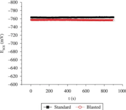
In relation to the corrosion potential of both steel samples, standard and blasted, they did not present signiicant variation, as shown in Figure 4. This result shows that blasting did not affect the electrochemical behavior of steel.
The roughness parameters shown in Table 1 were obtained with the confocal microscope for the two supericial conditions considered in this study.
The increase in supericial area as a function of blasting was quantiied using the ratio between the two supericial area parameters, resulting in a dimensionless area factor F that will be used as the supericial area correlation factor.
2 blasted
2 standard
A 3.725mm
Area Factor F 1.880
A 1.981mm
= = = = (12)
A typical passivation process behavior was obtained from the anodic polarization of the samples for different rotation conditions, as shown in Figure 5. This shows the polarization curves measured at rotation rates of 0, 400, 800 e 1200 rpm. It is observed that the corrosion current density (Icor) on polarization curves increases according to the rotation rate until at certain value, after that the corrosion rate density (Icor) decrease. The higher peak value is reached in 800 rpm, at this point the turbulent low enhances mass transport of species to and away from the steel surface by affecting transport through the boundary layer. For 1200 rpm rotation, there is an inversion of the phenomenon that could be associated with changes in the conditions of the low on the surface caused by the proile of boundary layer15. This behavior is discussed below.
Figure 6 shows the values of CO2 corrosion rate, expressed as a function of the rotation rate for both supericial inish conditions: standard and increased roughness (blasted).
Figure 3. AISI 1020 steel at 25 °C in a 0.5 M NaHCO3 solution
purged with CO2, 1 atm, pH 7.5 and stagnant condition. SEM image of top view with respective EDS analysis.
Figure 2. Variation in cylinder tangential velocity as a function of
cylinder rotation rate.
Figure 4. Comparison between the corrosion potential for AISI
1020 steel with standard surface and surface blasted, at 25 °C in a 0.5 M NaHCO3 solution purged with CO2, 1 atm, pH 7.5 and stagnant condition.
Table 1. Roughness and area measurements.
Ra (μm) A (mm2)
Standard sample 1.076 1.981
The area factor, F = 1.880 (Equation 12), of the cylinder surface with the increased roughness, was considered in the Stern-Geary equation and the new corrosion rate was obtained, this corrosion rate was represented by corrected roughness curve. The CO2 corrosion rate value shows a clear dependence on the rotation rate and supericial inish conditions. This can be explained mainly by the action of the viscous forces on the liquid mass, originating both from
the quality of the interaction between the species present in the luid (velocity) and from the luid/electrode border effect (roughness).
When the electrode rotation increases, causing an increase in its supericial velocity in order to reach a turbulent low regime, two different regions appear: one next to the cylinder wall and another involving the remaining luid. In the region adjacent to the metal/luid border, called the hydrodynamic boundary layer, the luid molecules in contact with the metallic surface adhere to the surface and cause a stagnation effect in the solution, which develops a velocity gradient.
In the laminar boundary layer condition, the dissolution mechanism of the Fe2+ species increases according to the velocity, until it reaches a transition region. The experimental results obtained showed that the type of interaction on the electrode surface with the luid is modiied for velocities near 400 rpm, and is displaced to the laminar boundary layer (region I) to the right (region II) as shown in Figure 7. The hydrodynamics on the cylinder electrode surface is considered uniform for each rotation condition. This means that with the increase in cylinder rotation the hydrodynamic condition on the electrode surface changes from static behavior to laminar behavior to one corresponding to the transition regime until it reaches the totally turbulent low in which the laminar underlayer is formed.
In the transition region, region II in Figure 7, the Fe2+ and CO32– species begin to experience the rotation movement (micro vortices) that makes solution saturation dificult and increases the pH between the FeCO3 layer pores, resulting in a corrosion rate peak.
When the electrode velocity is increased even more, the boundary layer is displaced to the turbulent condition (region III), developing an underlayer called laminar underlayer (see Figure 7). In the laminar underlayer, the viscous effects are important and allow not only the formation of a protective layer, but also its positioning on the electrode surface, a pH increase and solution saturation between the pores, progressively reducing the corrosion rate since the underlayer thickness reduces with the increased low and there is formation of Fe3O4 in the pores of the iron carbonate layer.
When the laminar underlayer condition is reached in surfaces with less roughness, the corrosion processes are similar to the condition of the luid at rest. The corrosion rate decrease due to the increase in the diffusion gradient of the reactive species since the underlayer thickness is quite reduced, which favors solution saturation between the pores.
When the friction factor of the cylinder surface with the increased roughness was taken into consideration, the experimental results showed that roughness facilitates the precipitation mechanism of the FeCO3 layer and increases the shear stress of the luid. When the cylinder velocity and the shear stress of the luid are increased, the luid interaction with the surface quickly goes from a laminar regime to the transition region. The supericial irregularities in the transition region permit the formation of micro vortices and this phenomenon progressively increases the steel corrosion rate as shown in Figure 6. Thus, the increase in supericial roughness causes an increase in the corrosion rate without allowing the electrode surface to experience the laminar underlayer condition. It follows that the corrosion rate remains high for the velocity low range evaluated.
Figure 5. Anodic polarization curves at different rotation rates: 0,
400, 800 and 1200 RPM. of AISI 1020 steel AT 25 °C in a 0.5 M NaHCO3 solution purged with CO2, 1 atm, pH 7.5.
Figure 6. CO2 Corrosion rates obtained by lpr method at four
rotation rates: 0, 400, 800 and 1200 RPM from each supericial inish
conditions: standard, increased roughness (blasted) and corrected roughness. of AISI 1020 steel at 25 °C in a 0.5 M NaHCO3 solution purged with CO2, 1 atm, pH 7.5.
4. Conclusions
The behavior described in this paper indicates the inluence of the laminar/turbulent low transition zone on dissolution kinetics and on the formation of the iron carbonate layer. The maximum CO2 corrosion rate value obtained for the smoother electrode occurs when the structure of the hydrodynamic boundary layer is between the turbulent and laminar regions and may be associated with this transition region in which micro vortices and, consequently, high agitation of the
species near the surface, are observed and inhibit the FeCO3 layer precipitation process. When surface roughness was considered in the corrosion rate calculations, from the area factor, F, the corrosion rate for corrected roughness, decreased for all rotation rates conditions, due to an increase in area available for the anodic reaction. However, turbulent low has different effects on standard and rough surface. On the surface roughness, the turbulent eddies enhance the low-induced corrosion and an increase in rotation rate results in an increase in corrosion rate.
References
1. Dugstad A and Halseid M. Internal corrosion in dense phase CO2 transport pipelines: state of the art and the need for further
R&D. Houston: NACE International; 2012. Corrosion Paper
nº 0001452.
2. Le Crolet J, Thevenot N and Nesic S. Role of conductive corrosion products in the protectiveness of corrosion layers. Corrosion. 1998; 54(3):194-203. http://dx.doi.org/10.5006/1.3284844. 3. Le Crolet J and Bonis MR. pH measurement in aqueous co2
solutions under high pressure and temperature. Corrosion. 1983; 39(2):39-46. http://dx.doi.org/10.5006/1.3580813.
4. Nesic S, Shihuai W, Cai J and Xiao Y. Integrated CO2 corrosion:
multiphase low model. Houston: NACE International. Corrosion Paper nº 04626.
5. Han J, Young D and Nesic S. Characterization of the passive
ilm on mild steel in CO2 environments. Houston: NACE International. Corrosion Paper nº 2511.
6. Hassani SH, Roberts KP, Shirazi SA, Shadley JR, Rybicki EF and Joia C. Flow loop study of NaCl concentration effect on erosion, corrosion and erosion-corrosion of carbon steel in CO2-satured systems. Corrosion. 2012; 68(2):026001-1-026001-9. http://dx.doi.org/10.5006/1.3683229.
7. Ferreira LRM. Avaliação da corrosão por luxo do aço AISI
1020 em solução de NaHCO3 saturada de CO2. [Dissertation].
Curitiba: Parana Federal University; 2012.
8. Shayegani M, Ghorbani M, Afshar A and Rahmaniyan M. Modelling of carbon dioxide corrosion of steel with iron carbonate
precipitation. Corrosion Engineering, Science and Technology. 2009; 44(2):128-136. http://dx.doi.org/10.1179/174327808X286338.
9. Nesic S, Postlethwaite J and Olsen S. An Electrochemical Model for Prediction of Corrosion of Mild Steel in Aqueous Carbon Dioxide Solution. Corrosion. 1996; 52(4):280-294. http://dx.doi.org/10.5006/1.3293640.
10. Han J, Young D and Nesic S. Characterization of the passive
ilm on mild steel in CO2 environments. Houston: NACE International; 2009. Corrosion Paper nº 2511.
11. Asma RBA, Yuli PA and Mokhtar CI. Study on the effect of surface finish on corrosion of carbon steel in CO2 environment.
Journal of Applied Sciences. 2011; 11(11):2053-2057. http://
dx.doi.org/10.3923/jas.2011.2053.2057.
12. Fox RW. Introduction to luid mechanics. 4th ed. John Wiley & Sons; 1992.
13. Silverman DC and Winston R. Pratical corrosion prediction using electrochemical techniques. In: Winston Revie R, editor.
Uhlig’s Corrosion Handbook. 3th ed. Hoboken: John Wiley &
Sons; 2011.
14. American Society for Testing and Materials - ASTM. ASTM G185-06: standard practice for evaluating and qualifying oil
ield and reinery corrosion inhibitors the rotating cylinder
electrode. West Conshohocken.
15. Welty JR, Wicks CE, Wilson RE and Rorrer G. Fundamentals
of momentum, heat and mass transfer. 4th ed. John Wiley &