*e-mail: [email protected], [email protected]
1. Introduction
Computational Fluid Dynamics (CFD) techniques (3-11)
are inding new and important industrial applications in the materials science related ields of Severe Plastic Deformation (SPD) (1,3,5-10) . Minakowski (2014) has applied CFD-based
techniques to a mathematical description of the low of an aluminum workpiece during Equal Channel Angular Extrusion (ECAE) through a 2-turn angular die with internal
and external radii in the channel intersection zones (3).
Perig et al., have solved the Navier-Stokes equations in a curl transfer form for the ECAE problem of workpiece viscous low (5-8). Perig and Golodenko have applied CFD
techniques to the numerical solution of the 2D problem for viscous material ECAE through a 2-turn multiple-angle S-shaped die with a movable inlet wall (6). Perig et al., have
applied a CFD-based method of numerical integration of a curl transfer equation for viscous low of a workpiece through a die with parallel slants in the channel intersection
zone (7) . Rejaeian and Aghaie-Khafri (2014) have applied
a CFD-based stream function technique to a velocity ield derivation in the channel intersection zone during ECAE of a workpiece through an angular die with external and internal
radii in the channel intersection zone (10) . At the present time
further development of SPD processing schemes during Equal Channel Multiple Angular Extrusion (ECMAE) is grounded on further increases in workpiece length and increases in accumulated shear deformations within the worked material
volume by increasing the quantity of deformation zones for every pass of ECMAE (1,6,7).
The principal goal of ECMAE pressure working of polymer materials is focused on the introduction and accumulation of large plastic deformations in the polymer workpiece for further fragmentation of lamellar polymer structure with mechanical properties enhancement while retaining the optical transparency of processed polymer workpiece (1,4-8) . Possible applications for ECMAE worked
polymers are associated with aeronautical and chemical
industry equipment production (1,4-8) .
The solution of the above mentioned technological problems is within the aims and scopes of research, conducted by Beloshenko et al., (2009) 1, Minakowski (2014) 3 Perig et al.
(2014) (5-9) , and Rejaeian and Aghaiae-Khafri (2014) (10) ,
and a number of other researchers (2,4,12,13) .
The 2-turn, 3-turn, ..., and n-turn ECMAE dies with geometries of S –, U –, T –, X –, W – types could be classiied
as multiple angle dies (1,3,6,7). So the character of local low of
workpieces during ECMAE is determined both by geometric features of the die tooling and by the rheology of deformable
metal (10) , polymer (1,3-8), powder, and composite materials.
Both the die geometry (Figs. (1 – 2)) and the workpiece
rheology (Figs. (3,4)) determine the kinematic and dynamic
features of the local low, rotation angles of the principal axes of the low, and the heterogeneity of material rotation during workpiece forming through the U-die.
CFD 2D Description of Local Flow of Polymer Workpiece through a modiied
U-Shaped Die During Equal Channel Multiple Angular Extrusion
Alexander V. Periga*, Nikolai N. Golodenkob
aManufacturing Processes and Automation Engineering Department, Donbass State Engineering
Academy, Shkadinova Str., 72, 84313, Kramatorsk, Ukraine
bDepartment of Water Supply, Water Disposal and Water Resources Protection, Donbass National
Academy of Civil Engineering and Architecture, Lazo Str., 14, 84333, Kramatorsk, Ukraine
Received: January 8, 2016; Revised: February 18, 2016; Accepted: March 11, 2016
The present article is focused on a 2D computational luid mechanics study of local viscous low dynamics and the formation character of rotary modes of deformation during Equal Channel Multiple Angular Extrusion (ECMAE) of a polymer workpiece luid model through a U-shaped die with parallel slants in channel intersection zones. The present local low problem was experimentally analyzed using physical simulation methods and theoretically studied with numerical luid mechanics techniques. The computational approach has been grounded on the numerical inite difference solution of the boundary value problem for the Navier-Stokes equations in the curl transfer form for the local viscous low of incompressible Newtonian luid through a U-shaped rectangular die with parallel slants. The derived research results allow us to draw a conclusion that the implementation of a geometric design of parallel slants within a 2-turn U-shaped die results in localization of the maximum tangential stresses within the workpiece volume to the vicinity of these parallel slants during ECMAE.
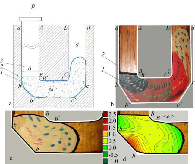
Fig. 1. ECMAE schemes of a truncated U-shaped die (1 – workpiece; 2 – split die; 3 – punch): (a) – scheme of the low of the workpiece;
(b) – workpiece physical model with the initial circular gridlines at the inal stage of illing the outlet channel cdCD of the U – shaped die; (c) – the soft physical model of deformable workpiece with the initial circular gridlines at the initial stage of illing the transition channel bb’BB’ of the U – shaped die; (d) – the experimentally-theoretical ield of logarithmic strain intensities for the one-component model (c).
Fig. 2. ECMAE schemes of a truncated U-shaped die: (a, c) – soft workpiece models; (b, d) – the experimentally-theoretical ields of
However the dynamics of macroscopic rotation during workpiece ECMAE through a U-shaped multiple-angle die is still not fully addressed in the previous known research
(1,3-10) , which emphasizes the importance and novelty of the
present article.
The objective of the present article is the estimation of kinematic and dynamic features of workpiece low in the channel intersection zones of a truncated U-shaped multiple-angle die with parallel slants, accounting for hydrodynamic effects of workpiece material viscosity.
2. Aims and Scopes of the Article. Prime
Novelty Statement of Research
The present article is focused on the experimental and theoretical description of viscous workpiece low through a U-shaped die with parallel slants in channel intersection zones.
The aim of the present research is the phenomenological continuum mechanics based description of viscous workpiece low through a U-shaped die with parallel slants in channel
intersection zones.
The subject of the present research is the process of ECAE working through a U-shaped die with parallel slants in channel intersection zones with viscous low of polymeric workpiece models, forced by the external action of standard
rectangular punch shapes.
The object of the present research is to establish the characteristics of the viscous low of workpiece models through the U-shaped die with parallel slants in channel intersection zones with respect to workpiece material rheology in the viscous ECAE process.
The experimental novelty of the present article is based on the introduction of initial circular gridlines to study the inluence of slanted U-shaped die on viscous workpiece ECMAE low.
The prime novelty of the present research is the numerical inite-difference solution of boundary value problem for Navier-Stokes equations in the curl transfer form for the viscous workpiece low through the U-shaped die with
parallel slants in channel intersection zones.
3. Physical Simulation Study of Viscous
Flow through a U-shaped die with
parallel slants in channel intersection
zones
To solve the posed problem experimentally we will analyze the workpiece local low features during ECMAE through an introduction of such physical simulation techniques as the marker method and the method of initial circular gridlines
(Figs. (1 – 2)).
Plasticine based physical simulation experiments in Figs. (1 – 2) are the new original experimental results, derived personally by the authors.
The experimental values of the Coulomb friction coeficient and the plastic friction factor in the Siebel (Tresca) friction law have been estimated with plasticine rings upsetting between two wooden plates. The plasticine rings were made with the following ratio of dimensions D:d:H=6:3:2,
where D is external diameter of plasticine ring, d is internal
diameter of plasticine ring, and H is the height of plasticine
ring (12,13) . It was experimentally determined by authors that
the Coulomb friction coeficient is f≈0.181 (τf=f•σn) and the
plastic friction factor in the Siebel (Tresca) friction law is m≈0.594 (τf=m•k; k=σS/30.5) for contact pair “wooden die model – plasticine workpiece model”, where τf is the friction stress; σn is the normal stress; k is the maximum tangential stress for plasticine material with low stress σS , i.e. the plastic constant k is the shear strength of the extruded material.
The initial plasticine physical models of the workpieces
in Figs. (1 – 2) were made in the shapes of rectangular
parallelepipeds. These rectangular parallelepipeds were frozen, the front sides of parallelepipeds were marked, and through-holes in parallelepipeds were perforated. Then the plasticine parallelepipeds with through-holes were frozen again. Simultaneously, plasticine pieces of different colors were heated to the half-solid state and placed into the through-holes of parallelepipeds through the application of squirt without needle. In this way the initial workpiece model was made in the shape of a rectangular parallelepiped and the initial circular plasticine gridline was formed within the plasticine model of the workpiece (Figs. (1 – 2)).
Simple new original physical simulation experiments of workpiece model low during ECMAE through a truncated U-shaped die with the channel width ā =40 mm are shown
in Figs. (1 – 2). The ECMAE truncated U-shaped die model
is fabricated from wood in Figs. (1 – 2), with the front part of the ECMAE die model fabricated with glassy plexiglass.
In Figs. (1 – 2) are outlined the plasticine physical models
with circular plasticine gridlines.
In Fig. 1 are shown ECMAE schemes (Fig. 1(a, b, c))
for pressing soft physical models of workpieces through a truncated U-shaped die (1 – workpiece; 2 – split die; 3 – punch), where channel width is ā =40 mm; the current values of workpiece lengths are LI≈ ⋅2 a =80 mm in
Fig. 1(c, d) and LIV ≈6 7 a. ⋅ =268 mm in Fig. 1(b), where
sufix numbers I and IV denote that the current physical model of the workpiece consists of one- Fig. 1(c, d) and
four- Fig. 1(b) components (Fig. 1).
In Fig. 2 are shown physical simulation-derived schemes
of the local low of the soft physical models of deformable workpiece with the initial circular gridlines at the inal stage of illing the transition channel b’c’B’C’ (Fig. 2(a, b)) and at
the initial stage of illing the outlet channel cdCD (Fig. 2(c, d))
of the U – shaped die, where channel width is a =40 mm; the
current values of workpiece lengths are LII≈3 5 a. ⋅ =140 mm (Fig. 2(a, b)) and LIII≈5 3 a. ⋅ =212 mm (Fig. 2(c, d)), where
sufix numbers II and III denote that the current physical model of the workpiece consists of two- (Fig. 2(a, b)) and three- (Fig. 2(c, d)) components.
The physical model of the long workpiece consisted of a 4-part model, which was formed by successive extrusion of the 4 initial short parts through the truncated U-shaped
die abb’c’cd – ABB’C’CD (Figs. (1(b, c) & 2(a, c))). As the total workpiece length increases, the viscous workpiece material successively ills the inlet channel abAB (Fig. 1a), the transition channel b’c’B’C’ (Figs. (1(c, d) & 2(a, b))),
The corresponding diagrams of logarithmic strain intensities 〈ei〉 have been derived on the basis of the experimental results (Figs. (1(b, c) & 2(a, c))) and are shown in Fig. 1d and
Fig. 2(b, d). Derived diagrams of 〈ei〉 show the character of successive displacement of the zones with the localization of maximum values of 〈ei〉 during workpiece ECMAE through a U-shaped die from the transition truncated die zone bb’BB’
(Figs. (1 – 2)) to the zone of the transitional die channel
b’c’B’C’ (Figs. (1 – 2)). The averaged values of experimental
strain intensities 〈ei〉 are: 0.490 in Fig. 1d; 0.458 in Fig. 2b, and 0.839 in Fig. 2d. This shows increasing values of 〈ei〉 as further deformation of the workpiece occurs through the truncated U-shaped die in Figs. (1 – 2).
We will introduce the term “average unevenness of logarithmic strain” as
(
max) (
max)
max
1 2
i i i i
iSU
i i
e e e e
e
e e
− −
= +
(1)
The averaged values of experimental unevenness of
logarithmic strain 〈eiSU〉 are: 1.07 in Fig. 1d; 0.892 in Fig. 2b,
and 12.341 in Fig. 2d. This shows increasing values of 〈eiSU〉 as further deformation of the workpiece occurs through the truncated U-shaped die to the outlet die channel cdCD
in Fig. 2c. The complex nature of the local low of the
workpiece material through the U-shaped die is additionally characterized by such deformation parameters as the degree of “mixing”, macroscopic rotation, and rotation non-uniformity. We will deine the degree of workpiece material “mixing” in Figs. (1(b, c) & 2(a, c)) as the inclination angle α of the major axis of the deformable elliptical marker with the directions ab, bb’, b’c’, c’c, cd of the workpiece low. We will deine
the macroscopic rotation in Figs. (1(b, c) & 2(a, c)) as the
inclination angle increment Δα of the marker major axis with
the directions ab, bb’, b’c’, c’c, cd of the workpiece low. Experimentally measured average values of the degree of workpiece material “mixing” with and without accounting of algebraic signs of α have the following values: <α>=20.541° and <|α|>=20.246° in Fig. 1d; <α>=<|α|>=42.824° in Fig. 2b,
and <α>=36.887° and <|α|>=36.685° in Fig. 2d. These derived
experimental results show the general increase in workpiece material “mixing” as further deformation of the workpiece occurs through the truncated U-shaped ECMAE die to the
outlet die channel cdCD.
We will deine rotation non-uniformity of the material as the formation of inlection points and “intakes” within the elliptical markers. Such experimental patterns are visually observable at sections of the workpiece physical models in Figs. (1(b, c) & 2(a, c)).
4. CFD Simulation of Viscous Flow through
a U-shaped die with parallel slants in
channel intersection zones
We will apply a CFD-based technique Figs. (3 – 4) for a quantitative phenomenological description of macroscopic rotation dynamics, experimentally observable in Figs. (1(b, c) & 2(a, c)). We will introduce the Navier-Stokes equations for the CFD description of viscous low of the worked material physical models through the U-shaped
slanted die abb’c’cd – ABB’C’CD in Figs. (1(b, c) & 2(a, c)).
The theoretical background for the use of the Navier-Stokes
equations in the present article (Figs. (3 – 4)) is as follows.
For the anomalous or non-Newtonian liquids like plasticine models of polymer workpieces in Figs. (1(b, c) & 2(a, c)),
the law of internal friction is deined by the Bingham equation as τ = τ0 + ηvis·(dw/dz), where τ0 are the tangential
stresses within the luid at rest 4. The “plasticine” liquid in Figs. (1 – 2) can low only after overcoming the τ0 tangential
stresses. Then for τ > τ0 we have that τS = ηvis·(dw/dz), where τS = τ – τ0 is the degree to which the tangential stresses exceed
the luidity level. In this work we deal with the steady low
regime through the die abb’c’cd – ABB’C’CD, when the luidity level is overcome (Figs. (3 – 4)). So for the Bingham luid we have the same Navier-Stokes equations as in the case of a Newtonian liquid, but the computational values of the tangential stresses in reality are the overcoming of the tangential stresses over the luidity level. Taking into account all these considerations in this work we are using the Navier-Stokes equations as the irst ideal viscous approach to polymer low during ECMAE through the U-shaped
slanted die abb’c’cd – ABB’C’CD in Figs. (1(b, c) & 2(a, c)).
In order to derive the mathematical model of the viscous material low during ECMAE through the U-shaped slanted
die abb’c’cd – ABB’C’CD in Figs. (1 – 2) we will apply the
Navier-Stokes equations [4-8, 11]. To use both dimensional and dimensionless values of physical variables, we will mark dimensional values with overline symbols.
The curl transfer equation in dimensionless variables will have the following form [11]:
2 2
2 2
(u ) (v )
t x y x y
ζ ζ ζ ζ ζ
∂ = − ∂ +∂ +∂ +∂
∂ Re ∂ ∂ ∂ ∂
(2)
where the dimensionless curl function ζ (Fig. 3b) will be deined as:
u v
y x
ζ ∂= −∂
∂ ∂ (3)
Equations (2)-(3) we write in inite-difference form for further numerical integration according to the method of alternating directions. Flow function ψ (Fig. 3c) we
ind with Richardson iteration method. This article deals with a numerical estimate of the U-shaped slanted die geometric effect on viscous polymer planar low, based on a mathematical simulation of a Newtonian incompressible luid motion through a modiied abb’c’cd – ABB’C’CD die
with truncated deformation zones bb’ and c’c.
The numerical solution of the viscous low problem for material low in a U-shaped ECMAE slanted die (Figs. (1 – 2))
requires the formulation of a boundary value problem for the Navier-Stokes equation in the curl transfer form (2)-(3)
for ∂ζ/∂t=─Re(∂(uζ)/∂x+∂(vζ)/∂y)+∂2ζ/∂x2+∂2ζ/∂y2, where
ζ=∂u/∂y─∂v/∂x (Fig. 3b). We now study the steady-state regime of viscous low for a physical model of polymer
material (Figs. (3 – 4)). So the initial conditions we will
assume in the form of a rough approximation of the stationary
solution (Figs. (3 – 4)). For steady low of a viscous material
through a modiied ECMAE die abb’c’cd – ABB’C’CD, the
initial conditions are as follows:
0 0 0
, 1; 60, 20 1; 60, 60 1
i j ui j ui j
Die channel wall boundary conditions (BCs) are deined as the sticking of viscous material to the surface of die abb’c’cd – ABB’C’CD walls. So for the die walls the BCs are as follows:
for the nodes at the stream boundary (ABB’C’CD) we have
, 1; , 0; , 0; , 0
i j i j ui j vi j
ψ = ζ = = = (5)
for the nodes at the stream boundary (abb’c’cd) we have
, 0; , 0; , 0; , 0
i j i j ui j vi j
ψ = ζ = = = (6)
for the nodes at the stream boundaries (AB) and (cd)
we have
(
)
2, 2 , 1 ,
i j i j i j
ζ = ψ − −ψ η (7)
for the nodes at the stream boundary (B’C’) we have
(
)
2, 2 1, ,
i j i j i j
ζ = ψ+ −ψ ξ (8)
for the nodes at the stream boundaries (CD) and (ab)
we have
(
)
2, 2 , 1 ,
i j i j i j
ζ = ψ + −ψ η (9)
the following BC for dimensionless curl function ζ, written for the nodes, belonging to die wall (b’c’), must be satisied
(
)
2, 1, ,
i j 2 i j i j
ζ = ψ− −ψ η (10)
for the nodes at the stream boundary (bb’) we have
(
)
2, 2 1, , 1 2 ,
i j i j i j i j
ζ = ψ− +ψ + − ψ η (11)
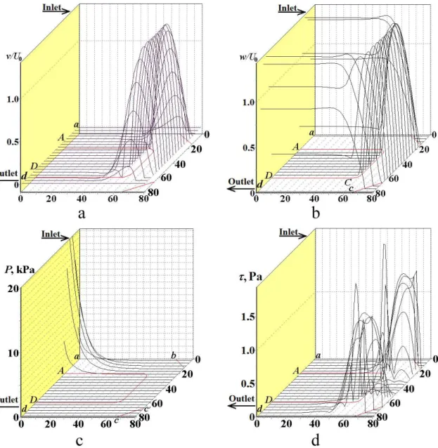
Fig. 3. CFD-derived low lines (a), curl function ζ (b), low function ψ (c), and dimensionless u-component of low velocity w (d), derived
for the nodes at the stream boundary (c’c) we have
(
)
2, 2 1, , 1 2 ,
i j i j i j i j
ζ = ψ− +ψ − − ψ η (12)
for the nodes at the stream boundary (BB’) we have
(
)
2, 2 1, , 1 2 ,
i j i j i j i j
ζ = ψ+ +ψ − − ψ η (13)
for the nodes at the stream boundary (C’C) we have
(
)
2, 2 1, , 1 2 ,
i j i j i j i j
ζ = ψ− +ψ − − ψ η (14)
for the angular points, located in the vertices of the “concave angles” b, b’, c, c’ we have
0
i, j
ζ = (15)
for the angular point B in the difference equation, written for the node (i, j – 1) we have
(
)
21
2 1
i, j i, j
ζ = ψ − − η (16)
for the angular point B in the difference equation, written for the node (i + 1, j) we have:
(
)
21 1
2 1
i, j i , j
ζ = ψ + − − ξ (17)
for the angular point C in the difference equation, written for the node (i, j + 1) we have
(
)
21
2 1
i, j i, j
ζ = ψ + − η (18)
Fig. 4. CFD-derived dimensionless v-component of low velocity w (a), dimensionless low velocity w (b), dimensional punching pressure
for the angular point C in the difference equation, written for the node (i + 1, j) we have
(
)
21 1
2 1
i, j i , j
ζ = ψ+ + − ξ (19)
for the angular point B’ in the difference equation, written for the node (i + 1, j) we have
(
)
21
2 1
i, j i , j
ζ = ψ+ − ξ (20)
for the angular point B’ in the difference equation, written for the node (i , j – 1) we have
(
)
2, 2 1 1 1
i j i , j
ζ = ψ+ − − ξ (21)
for the angular point C’ in the difference equation, written for the node (i + 1, j) we have (20).
for the angular point C’ in the difference equation, written for the node (i, j + 1) we have (19).
for the nodes at the entrance (Aa) of the multiple-angle die we have
20, 20, ; 20, 20, ; 20, 20,
i j j ui j u j vi j v j
ψ< =ψ < = < = (22)
For the nodes at the exit (Dd) of the multiple-angle die we have (22).
In the difference equations (5)-(22) parameters ξ; η are the steps of the inite-difference mesh. This article is focused on the CFD description of local low of polymer workpiece through a modiied U-shaped die during ECMAE, where the transient period of viscous low is 43.241 s in Figs. (3 – 4). The numerical computation results of the numerical integration of curl transfer equation (2)-(3) with initial (4) and boundary conditions (5)-(22) for the ields of the low lines and energy-power parameters are outlined in Figs. (3 – 4) for the following numerical values:
the dimensional width of inlet, outlet and transitional ECMAE die channel is ā=40 mm;
the dimensional density of the viscous plasticine physical model of extruded polymer material
is ρ=1850 kg/m3;
the dimensional plasticine yield strength is σs=217 kPa (Sofuoglu et al., 2000) [12];
the dimensional specific heat capacity of viscous plasticine material is c=1.004 kJ/(kg•K) (Chijiwa et al., 1981) (2) ;
the dimensional thermal conductivity is λ=0.7 J/ (m•s•K) (Chijiwa et al., 1981) 2;
the dimensional dynamic viscosity for viscous Newtonian luid model of the plasticine workpiece
is ηvis=135 Pa•s;
the dimensional kinematic viscosity for viscous Newtonian luid model of the plasticine workpiece ECAE is ν =η ρ=135 1850=0.0729 m / s2
vis vis ;
the dimensional characteristic average ECMAE punching velocity i.e. the workpiece velocity in
the entrance channel (ABab) of the ECMAE die is 3
0=0.27 10⋅ − m / s
U ;
the dimensionless Reynolds number is
(
3 3)
40 vis 0 vis 0.27 10 40 10 0.0729 1.48 10
U aρ η U aν − − −
= = = ⋅ ⋅ ⋅ = ⋅
Re ;
the dimensional time moment for the irst isochrone building is t1=100 s;
the maximum value of dimensionless curl is ζ = 15; the dimensional curl is
(
. 3) (
3)
. 3 10
U a 15 0 27 10 m/s 40 10 m 101 25 10 s
ζ ζ= ⋅ = ⋅ ⋅ − ⋅ − = ⋅ − − ;
the dimensional average angular velocity of rotation for processed viscous material elementary volume
is 3 1
2 2 50.625 10
rot s
ω= wr =ζ = ⋅ − − ;
the half number of coordinate steps along the x– and y– axes is q=20;
the coordinate increment is 2 mm;
the dimensional time iteration step is tit= 74 ms; the number of coordinate steps along the x– and y– axes is 2•q=40;
the relative error of iterations is e = 1/1000.
The authors’ written computer code for the numerical integration of the boundary value problem for curl transfer equation (2)-(3) with initial (4) and boundary conditions (5)-(22) has been proposed and practically realized by the authors with Object Pascal language.
5. Discussion of Derived Numerical
Simulation Results
The CFD problem (2)-(22) implicitly takes into account the maximum value of contact friction between the viscous amorphous polymer workpiece material and the walls of the U-shaped slanted die abb’c’cd – ABB’C’CD by the deinition of full sticking during viscous luid low. Note that there is an inluence of instabilities of numerical solutions of the CFD problem (2)-(22) at the entrance Aa and at the exit
Dd of the viscous low on the accuracy of the numerical
integration results in Figs. (3 – 4).
Instabilities of numerical inite-difference solutions of the CFD problem (2)-(22), which appear at the inlet boundary (Aa) of the U-shaped slanted die abb’c’cd – ABB’C’CD, propagate in the punching direction along U0, i.e. move downstream. Instabilities of numerical solutions of the CFD problem (2)- (22), which appear at the outlet frontiers (Dd), move toward the material low direction, i.e. propagate upstream.
The numerical solutions (Figs. (3 – 4)) for the ECMAE
through the U-shaped slanted die abb’c’cd – ABB’C’CD satisfactorily agree with the physical simulation results
(Figs. (1 – 2)) only when the inlet boundary (Aa) and outlet
boundary (Dd) of the viscous lows are located well away from the studied zone (BB’C’C – bb’c’c) of the transient die channel, i.e. ideally the channel inlet (Aa) and outlet (Dd) have to be ininitely distant from the die channel transient
chosen remote from the coordinate grid inlet boundary (Aa) of the viscous low (i = 0) and were chosen 20 cells away from the Aa boundary. Similarly for all 2D and 3D
plots in Figs. (3 – 4) the derived numerical ields have been
truncated 20 cells away from the outlet (Dd) inite-difference boundary (i = 80) in order to remove the computational distortions caused by the outlet (Dd) instabilities. So the inite difference grid cells near the inlet and outlet have been rejected from the plots in Figs. (3 – 4). We will now analyze and compare the results of the physical (Figs. (1 – 2)) and numerical (Figs. (3 – 4)) experiments.
The proposed die geometry in (Figs. (1 – 4)) has two slanted zones bb’BB’ and c’cC’C, which prevent dead zone formation in the vicinity of truncated external corners during viscous low of the workpiece model through the U-shaped slanted die. The absence of the dead zones is shown in experimental photos (Figs. (1(b, c) & 2(a, c))), in computational low lines (Fig. 3a), and in computational low function ψ diagrams (Fig. 3c). The experimentally-derived plots in
Figs. (1(b, c) & 2(a, c)) successively illustrate localization of zones with maximum values of logarithmic strain intensities.
The experimental 2D diagrams in Figs. (1(d) & 2(b, d))
show the dynamics of displacement of the deformation zone within the deformed material as the workpiece is punched through the U-shaped slanted die during ECMAE. The irst experimentally-derived strain diagram in Fig. 1d shows that at
the initial stage of the low the deformation zone is located in the vicinity of the line bb’, i.e. includes the “external ibers” of deformed material, which are adjacent to transitional left lower slant bb’. The second experimentally-derived strain
diagram in Fig. 2b indicates that at the inal stage of illing the transition channel b’c’B’C’ of the U – shaped die the deformation zone within the workpiece volume completely moves to the vicinity of the horizontal internal transition
zone B’C’, i.e. the deformation zone occupies “internal ibers” of deformable material B’C’, and, so, the deformation zone goes beyond the 1st slanted zone bb’BB’. The third
experimentally-derived strain diagram in Fig. 2d shows the
initial stage of illing the outlet channel cdCD of the U – shaped die and shows the displacement of the deformation zone in the vicinity of the horizontal external transition wall b’c’,
i.e. the new localization of the deformation zone includes the “external ibers” of deformed material in the vicinity of the low border b’c’. The proposed original physical simulation, outlined in Figs. (1 – 2), shows the dynamics of successive
deformation working of the workpiece by punching and “mixing” both “external” and “internal” ibers of the long initial workpiece, that provides accumulation of the large shear strains for every pass of ECMAE through the U-shaped die.
The CFD-derived diagrams for flow velocities (Figs. (3(d) & 4(a, b))) and tangential stresses (Fig. 4d)
additionally show that as the workpiece goes to the outlet channel of the U-shaped die, the formation of velocity and tangential stress gradients occur within the workpiece volume and localization of these gradients exactly corresponds to the zones of the two slants bb’BB’ and c’cC’C. The observable formation of tangential stress gradients on the CFD-derived
diagram in Fig. 4d is the hydrodynamic illustration of the
appearance of the rotational deformation modes, which are visually observable in the experiment, shown in Figs. (1 – 2).
The combined use of the physical simulation (Figs. (1 – 2)) and numerical CFD techniques (Figs. (3 – 4)) provides
new experimental-theoretical results, which illustrate the dynamics of local material low during SPD with ECMAE through truncated U-shaped dies. The proposed CFD-based
approach (Figs. (3 – 4)) is appropriate for the analysis of
ECMAE through the multiple-angled dies with more complex geometries of S –, T –, X –, W – types, taking into account the availability of the movable inlet, transitional, and outlet die walls.
6. Conclusions
The derived experimental-theoretical results allow the conclusion, that the geometric realization of the parallel slants in the two-turn truncated U-shaped die results in localization of the maximum tangential stresses within the workpiece worked material in the vicinity of the parallel slants during Equal Channel Multiple Angular Extrusion.
The derived experimental-theoretical results are grounded on the empirical analysis of the initial circular gridlines, and on the results of numerical inite-difference solution of the Navier-Stokes equations in curl transfer form for the local viscous low of incompressible Newtonian viscous luid through the truncated slanted multiple-angled U-shaped die.
The derived experimental-theoretical results enhance the understanding of local low dynamics and the character of the formation of the rotational modes of deformations during Equal Channel Multiple Angle Extrusion through a truncated slanted multiple-angled U-shaped die. These results may lead to further applications to the analysis of shear lows in multiple-angled dies of more complex geometry with additional kinematical constraints in the shape of the moving walls.
Disclosure
The submission of the authors’ paper implies that it has not been previously published, that it is not under consideration for publication elsewhere, and that it will not be published elsewhere in the same form without the written permission of the editors.
Conflict of Interests
The authors Alexander V. Perig and Nikolai N. Golodenko declare that there is no conlict of interests regarding the publication of this paper.
Authors’ contributions
All authors participated in the design of this work and performed equally. All authors read and approved the inal
manuscript.
Compliance with ethical guidelines
Competing interests. The authors declare that they have no competing interests.
Acknowledgements
References
1. Beloshenko VA, Voznyak A, Voznyak Y. Solid-phase extrusion of polyamide under simple shear. Polymer Science Series A. 2009;51(8):916-922. http://dx.doi.org/10.1134/S0965545X09080112 2. Chijiiwa K, Hatamura Y, Hasegawa N. Characteristics
of plasticine used in the simulation of slab in rolling and
continuous casting. Transactions of the Iron and Steel Institute of Japan. 1981;21(3):178-186. http://dx.doi.org/10.2355/ isijinternational1966.21.178
3. Minakowski P. Fluid model of crystal plasticity: numerical simulations of 2-turn equal channel angular extrusion. Technische Mechanik. 2014;34(3-4):213-221. http://www.uni-magdeburg. de/ifme/zeitschrift_tm/02_HTML_Inhalt/2014.htm
4. Oswald P. Rheophysics. The deformation and low of matter.
New York: Cambridge University Press; 2009.
5. Perig AV, Laptev AM, Golodenko NN, Erfort Yu A, Bondarenko EA. Equal channel angular extrusion of soft solids. Materials Science and Engineering A. 2010;527(16-17):3769-3776. http://
dx.doi.org/10.1016/j.msea.2010.03.043
6. Perig AV, Golodenko NN. CFD Simulation of ECAE through a multiple-angle die with a movable inlet wall. Chemical Engineering Communications. 2014;201(9):1221-1239. http:// dx.doi.org/10.1080/00986445.2014.894509
7. Perig AV, Golodenko NN. CFD 2D simulation of viscous flow during ECAE through a rectangular die with parallel slants.
International Journal of Advanced Manufacturing Technology. 2014;74(5-8):943-962.
http://dx.doi.org/10.1007/s00170-014-5827-2
8. Perig AV, Golodenko NN. ECAP process improvement based on the design of rational inclined punch shapes for the acute-angled Segal 2θ-dies: CFD 2-D description of dead zone
reduction. Mechanical Science. 2015;6(1):41-49. http://dx.doi. org/10.5194/ms-6-41-2015
9. Perig AV. Two-parameter rigid block approach to upper bound analysis of equal channel angular extrusion through a Segal 2θ-Die. Materials Research. 2015;18(3):628-638. http://dx.doi.
org/10.1590/1516-1439.004215
10. Rejaeian M, Aghaie-Khafri M. Study of ECAP based on stream function. Mechanical Science. 2014;76:27-34. http://dx.doi. org/10.1016/j.mechmat.2014.05.004
11. Roache PJ. Computational Fluid Dynamics. Albuquerque:
Hermosa Publishers; 1976.
12. Sofuoglu H, Rasty J. Flow behavior of plasticine used in physical modeling of metal forming processes. Tribology International. 2000;33(8):523-529. http://dx.doi.org/10.1016/
S0301-679X(00)00092-X
13. Wang JP. A new evaluation to friction analysis for the ring
test. International Journal of Machine Tools and Manufacture.
2001;41(3):311-324.