Abstract
This article presents the vibro-acoustic modeling and analysis of un-baffled laminated composite flat panels subjected to harmonic point load under various support conditions. The frequency values of the panel are obtained by using simulation model through the commercial finite element package (ANSYS) via batch input tech-nique. Initially, the rate of convergence of the current simulation results is established by solving different examples under various edge supports. Further, the natural frequencies and corresponding modes are computed and compared with available published and experimentally obtained values. Then, the modal values are export-ed to LMS Virtual.Lab environment for the computation of acous-tic responses of the vibrating laminated plate structure. Further, an indirect boundary element approach has been adopted to extract the coupled vibro-acoustic responses. Subsequently, the radiated sound power of the structure and the sound pressure level within the acoustic medium are computed using the present scheme and compared with the published numerical results and in-house exper-imental data, respectively. Finally, a comprehensive study has been performed to highlight the effect of different structural parameters (thickness ratio, aspect ratio, modular ratio and lay-up scheme), support conditions and the composite properties on the acoustic radiation responses of the laminated plate structure.
Keywords
Laminated composite; Modal analysis; Indirect boundary element method; SPL; Radiated sound power; Experimental analysis.
Numerical Study of Vibro-Acoustic Responses of Un-Baffled
Multi-Layered Composite Structure under Various End
Conditions and Experimental Validation
1 INTRODUCTION
Laminated composite structural components are extensively preferred over conventional materials in today’s high-performance engineering applications (aerospace, aircraft, automobile and marine
engi-Nitin Sharma a
Trupti Ranjan Mahapatra b
Subrata Kumar Panda c
a Ph.D Stu., Sch. of Mech. Engineering,
KIIT University, Bhubaneswar, Odisha, India, nits.iiit@gmail.com
b Assoc. Prof., Sch. of Mech. Eng., KIIT
University, Bhubaneswar, Odisha, India, trmahapatrafme@kiit.ac.in
truptiranjan01@gmail.com
c Asst. Prof., Dept. of Mech. Eng., NIT,
Rourkela, Odisha, India, call2subrat@gmail.com
http://dx.doi.org/10.1590/1679-78253830
neering) not only for their specific strength and stiffness properties but also largely due to their light weight characteristic which is highly desirable according to the present demand. However, the re-duction in weight of the structure may lead to increased levels of noise which is proportional to the magnitude and frequency of the structural vibrations. Therefore, the designer quest to minimize the noise radiated into the surroundings during the design and fabrication of the light-weight laminated structural components due to their paramount importance in such applications. Hence, the sound radiation characteristics need to be investigated judiciously and the design together with the fabri-cation process must be handled suitably. It is well known that, a radiation response indicator is essential for the representation of the acoustic radiation via a vibrating structure so that the veloci-ty on the boundary and the sound radiation can be related. Thus, it plays an important role in the evaluation of the magnitude of the acoustic disturbances accurately. In this regard, various acoustic radiation mode theories including the structure dependent radiation mode analysis steps have been evolved in the past with an intention to figure out the realistic acoustic radiation in the surrounding medium due to the vibrating structures (baffled and un-baffled plates and beams) (Atalla and Sgard, 2015). The acoustic radiation of the flat rectangular plate in a rigid baffle is usually obtained by Rayleigh integral formulation and often used as the basis for the analysis of sound radiation analysis for more complex structures. This scheme is further extended by other researchers successively in the past to explore the possible effect of angle of the baffle and the end constraint conditions on the acoustic radiation behaviour (Putra and Thompson, 2010). The first radiation mode amplitude of the composite and the isotropic plate structures have frequently been employed to account the acoustic behaviour (Petrone et al., 2014). However, so far as the analysis of laminated and sandwich structures is concerned, the existing and/or refined 2D and shear deformation theories are mainly employed to obtain the vibration responses of the structure and the acoustic radiation is computed using Rayleigh integral (Petrone et al., 2014). However, we also note that, in those studies the use of structure dependent radiation modes is preferred over the conventional acoustic radiation modes to quantify the acoustic radiation from the vibrating structures (Ohlrich and Hugin, 2004).
envi-ronment. The classical laminated plate theory (CLPT) has been used to model the structure and the acoustic response is obtained using coupled FEM/BEM solver in LMS SYSNOISE software. Yin and Cui (2009) studied the effect of the lay-up scheme on the acoustic behaviour of laminated com-posite plates under different loading schemes, namely transverse and longitudinal. Acoustic radia-tion from a funcradia-tionally graded (FG) elliptic disc in a thermal environment has been studied by Kumar et al. (2009) by using FEM/BEM approach and LMS SYSNOISE software. Zhao et al. (2013) considered a simply supported laminated composite flat plate vibrating in a hygroscopic environment and obtained the acoustic response by using Rayleigh integral formulation. Nowak and Zielinski (2015) used an indirect variational BEM to get the acoustic radiation from vibrating rec-tangular plate for various boundary conditions. The frequencies and the corresponding vibrational mode shapes of the plate are computed using the FEM. The effect of support conditions on the velocity and acoustic response of vibrating rectangular isotropic baffled plates has also been studied using Rayleigh integral formulation (Park et al., 2003; Qiao and Huang, 2007). The support tuning is observed to yield significant noise and vibration reduction. Huang et al. (2005) investigated the free vibration behaviour of orthotropic rectangular plates with varying thickness under general boundary conditions. Shojaeefard et al. (2014) presented an analytical solution for calculating the sound transmission loss of thick orthotropic cylindrical shell using third order shear deformation
theory (TSDT).
It is clear from the brief review of the literature that the boundary conditions, along with the other parameters such as type of excitation, location of excitation, material properties etc. play an important role in determining the acoustic radiation behaviour of structures. We also note that the studies related to the vibro-acoustic response of baffled isotropic plates are more in number in com-parison to the baffled and/or un-baffled laminated composite structures. However, theoretical and numerical studies addressing the effect of frequently used support conditions on the acoustic radia-tion characteristics of an un-baffled orthotropic laminated composite flat panel under the acradia-tion of harmonic point loads are scarce. In order to address this issue, in this paper an attempt has been made to study the sound radiation characteristic of the un-baffled laminated composite flat panels under several support conditions and subjected to harmonic point excitation. First, a simulation model for the vibrating flat panel has been developed in commercial FE software ANSYS using ANSYS parametric design language (APDL) code and the natural frequencies are computed. Then, these free vibration responses have been utilised to carry out the coupled vibro-acoustic analysis via indirect BEM method in LMS Virtual.Lab environment. In order to validate the proposed scheme, the present results are compared with the numerical data available in open literature. Further, lab scale experiments have been conducted to obtain the free vibration and the acoustic responses of the laminated composite plates and compared with the current numerical results. Finally, the effect of aspect ratio, thickness ratio, modular ratio and the lamination scheme on the acoustic radiation characteristics (sound pressure level and radiated sound power) of an un-baffled laminated compo-site flat panel under different support conditions have been investigated and discussed in detail.
2 THEORETICAL BACKGROUND
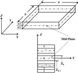
length a, width b and thickness h. In order to compute the free vibration responses, a simulation model of the flat panel has been developed in ANSYS environment using APDL code. The Shell 281 element has been chosen from the ANSYS element library for the discretization of the present mod-el. The element is a serendipity (eight noded) element with six degrees freedom per node and capa-ble of solving thin to moderately thick shell panel structure. The mid-plane kinematic for the panel structure is defined based on the first order shear deformation theory (FSDT) and conceded as:
(
)
( )
( )
(
)
( )
( )
(
)
( )
( )
0
0
0
, , , , ,
, , , , ,
, , , , ,
x
y
z u x y z t u x y z x y v x y z t v x y z x y w x y z t w x y z x y
q q q
= +
= +
= +
(1)
where, u, v andware the displacements of any point on the Kth layer of the composite lamina at time “t” along the x, y andzcoordinate axes, respectively;
u
0, v0 andw
0 are the correspondingdisplacements of a point on the mid-plane;
q
xandq
y are the rotations of normal to the mid-surface(z = 0) about the y andxaxes, respectively;
q
zis the higher order term in the Taylor series expan-sion which accounts for the linear variation of displacement function along thickness direction.Figure 1: Geometry and lay-up scheme of laminated composite flat panel.
Now, this simulation model has been employed to perform the modal analysis as well as extract the necessary modal values of the structure. Further, the values are provided as the input for the acoustic analysis. The in-vacuo modes of the vibrating structure can be obtained by solving the following eigenvalue equation (Cook et al., 2000):
{ }
2
([ ]
K
-
w
[ ])
M
F =
0
(2)where, [ ]K and [M ] are the stiffness and mass matrices, respectively, w is the natural frequency of
vibration, and { }F is the corresponding mode shape vector. The mode shapes corresponding to each
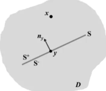
It is apparent from the review of literature that the BEM has been widely appreciated for solv-ing the coupled vibro-acoustics problems efficiently. In the present study the indirect BEM has been used for modelling the fluid medium and the sound radiation is computed on both sides of the mesh. For the theoretical development an un-baffled vibrating flat panel having fluid on both of its sides is considered as shown in Figure 2. The governing equation for the acoustic problems is the well-known Helmholtz wave equation which is expressed as:
2p k p2 0
+ = in the fluid medium D. (3)
where, 2is the laplacian,
k
=
w
c
is the wave number,p is the acoustic pressure, w is the
angu-lar frequency, c is the speed of sound in the surrounding acoustic medium (D) and S+ and S
-denote the two separate sides of the surface S such thatS =S+ ÈS-.
Figure 2: Un-baffled flat panel in acoustic medium.
The indirect BEM method involves the modelling of acoustic variables in the form of potentials, namely the single layer potential σand the double layer potential µ. These potentials are related to the acoustic pressure and velocity jumps across the surface S as:
p p
n n
s = ¶ + - 
-¶ ¶ (4)
and,
p
p
m
=
+-
- (5)where, superscript ‘+’ indicates the values on the positive side defined by the outward normal vec-tor at the surface S+, and the superscript ‘
’ indicates values on the opposite side, i.e. S-. Now,using the potentials defined in the aforementioned lines, the solution to the Helmholtz wave equa-tion takes the following form as in (Nowak and Zielinski, 2015):
[ xy ]
x xy y y y
y S
G
p G dS
n
s ¶ m
= -
-
ò
, " Ïx S and yÎS (6)1 4 jkr xy G e r p -= (7)
where, r is the distance between the source point y and the field point x.
Now, Eq. (3) is solved by imposing Neumann boundary condition on the entire surface S of the
vibrating flat panel given as:
0
s = , and n y p j V n wr ¶ =
-¶ for y ÎS (8)
where,
V
n is the normal component of velocity of the structure. On imposing the boundarycondi-tion given by Eq. (8), Eq. (6) can be re-written as:
2
xy
n y y
x y S
G
j V dS
n n
wr m 
- =
¶ 
ò
(9)Now, Eq. (9) needs to be solved for an unknown potential
m
defined on the surface S. Thesolu-tion to the integral equasolu-tion can be obtained by minimizing the funcsolu-tional J defined as in (Qiao
and Huang, 2007):
2
,
2 x n y x y xy x y
x y
S S S
G
J j V dS dS
n n
wrm m m 
= +
¶ 
ò
ò ò
(10)Subsequently, Eq. (10) is rewritten by using the properties of Green’s function
G
and thecon-tinuity of
m
over S (Tournour and Atalla, 1998):{ }
2 2 [ ( ) ( ) ( )] [ ( )] xyx y x y xy x y x y x y x y
x y
S S S S
G
dS dS G k n n dS dS n n
D
m m m m m m
m w m
üï
¶ ïï
= ⋅ - ´ ⋅ ´ ï
¶ ¶ ýï
ïï
= ïþ
ò ò
ò ò
(11)And
{ }
, [ ]
x n y S
jwrmV = U C m
ò
(12)where, U is the degree of freedom vector of the structure. Therefore, a coupled equation represent-ing the structure and acoustic medium can be written as:
2 2 1 0 ( ) T
K i M C
U F C D w w m w rw
æ + Q - ö÷
ç ÷ï ïì ü ì üï ï
ç ÷ï ï ï ï
ç ÷ =
ç ÷í ý í ý
ç - ÷ï ï ï ï
ç ÷ï ï÷î þ ï ïî þ
ç ÷
çè ø
(13)
where, Θ is the damping matrix and
F
is the external load vector. The system is symmetric,The acoustic radiation impedance matrix is defined as (Atalla and Sgard, 2015):
1
( )
( )
TZ
w
=-
j CD
rw
w
-C
(14)The sound power radiated (
W
rad) by the vibrating plate is given by (Atalla and Sgard, 2015):{ }
2
* real[ ( )]
2 rad
W = w U Z w U (15)
The radiated sound power level is expressed as:
Sound Power Level 10 log rad
ref W W
æ ö÷
ç ÷
ç
= ´ ç ÷÷
ç ÷
è ø (16)
where, Wref is the reference power and in the present analysis it is taken to be equal to 10-12 W.
The normal mean square velocity ( 2
n
v ) on the surface S can be written as (Atalla and Sgard,
2015):
2 ( ) 1 2
2
n n
S
v V dS S
w =
ò
(17)The radiation efficiency (Ω) is a measure of the ability of the structure to radiate sound and is defined as (Atalla and Sgard, 2015):
2
rad
n
W
cS v
r
W = (18)
The sound pressure level (SPL) at a field point is given by:
SPL=20 log
ref p p
æ ö÷
ç ÷
ç
´ ç ÷÷
ç ÷
è ø (19)
where p is the pressure at the field point and ref
p
is the reference pressure equal to 20 Paμ .3 METHODOLOGY
The following steps are followed to obtain the coupled vibro-acoustic response of a vibrating flat panel:
1.The flat panel model is developed in ANSYS (in framework of FSDT mid-plane kinematics)
2.The modal analysis is performed after imposing appropriate support conditions and the natu-ral frequencies and the mode shapes are obtained. The various support conditions considered in the present analysis to reduce the number of unknowns are as follows:
(a) All edges clamped boundary condition (CCCC):
0
0
0
x
y
z
0
u
=
v
=
w
=
q
=
q
=
q
=
atx
0
and a; y 0 andb
.(b) All edges simply supported boundary condition (SSSS):
0
0
y
z
0
v
=
w
=
q
=
q
=
atx
0
and a;u
0
=
w
0
= =
q
x
q
z
=
0
at y 0 andb
.(c) One edge clamped and others free condition (CFFF):
0
0
0
x
y
z
0
u
=
v
=
w
=
q
=
q
=
q
=
atx
0
only.(d) All edges hinged boundary condition (HHHH)
0
0
0
y
z
0
u
=
v
=
w
=
q
=
q
=
atx
0
and a ;u
0
= =
v
0
w
0
=
q
x
=
q
z
=
0
at0
y and
b
.(e) All edges free boundary condition (FFFF)
0
0
0
x
y
z
0
u
=
v
=
w
=
q
=
q
=
q
¹
atx
0
and a; y 0 andb
.3.The ANSYS results file (.rst extension) containing the modal data, as obtained in step 2, is
imported into LMS Virtual.Lab environment for computing the acoustic response (Siemens LMS Virtual.Lab 13.5., Online help manual, 2015).
4.In LMS Virtual.Lab, an indirect BEM approach is adopted for obtaining the coupled
respons-es. The loads are attached to the appropriate nodes, a field mesh (representing the micro-phone locations) is defined for obtaining the acoustic responses and the problem is solved.
5.The results for radiated sound power, radiation efficiency, mean square velocity and sound
pressure at the field point are exported for further analysis.
The presently computed frequency responses and radiated sound power values are compared with those of the published numerical results. In addition, the numerically obtained values of the natural frequencies at different modes and the SPLs are compared with the present experimental results. The detailed experimental plan is depicted in the following section.
4 EXPERIMENTAL ANALYSIS
In order to obtain the free vibration (modal analysis) and acoustic responses of laminated composite flat panels, a lab scale experimental set-up has been developed at National Institute of Technology Rourkela (NIT, Rourkela), Odisha, India. For the experimentation purpose, two different laminated composites namely, six layered woven [0ᵒ/90ᵒ]3 glass/epoxy and four layered symmetric angle-ply
[±45ᵒ]s carbon/epoxy plates are fabricated using conventional hand lay-up technique. In order to
Parameters Glass/epoxy (Material: M1)
Carbon/epoxy (Material: M2)
Lamination Scheme [0ᵒ/90ᵒ]3 [±45ᵒ]s
a 0.15 m 0.15 m
b 0.15 m 0.15 m
h 0.002 m 0.00375 m
E1 7.205×10⁹ Pa 6.469×10⁹ Pa
E2= E3 6.327×10⁹ Pa 5.626×10⁹ Pa
ν12= ν23= ν13 0.17 0.3
G12= G13 2.8×10⁹ Pa 2.05×10⁹ Pa
G23 1.4×10⁹ Pa 1.025×10⁹ Pa
ρ 1420.05 kgm-3 1388 kgm-3
Table 1: Material properties of glass/epoxy and carbon/epoxy laminated composite plates used for the experimental analysis.
Figure 3 depicts the present experimental set-up used for recording the natural frequencies and
SPLs of the vibrating plate under cantilever (CFFF) support condition. The plate (1) is clamped
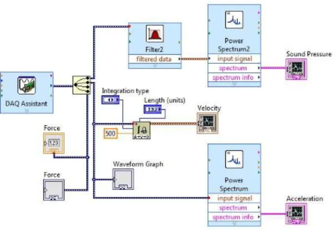
along one edge using the fixture (2). The impact hammer (3) is used to excite the plate at a par-ticular location on the plate, the signals generated are captured by the accelerometer (4), and the pressure in the surround medium is recorded by microphone (5). The accelerometer and the micro-phone are interfaced with LABVIEW through PXIe-1071 (6) that receives analogue voltage signal, uses an inbuilt AD (analogue to digital) converter to transform it into the digital signal form. Fur-ther, the digital signal is processed through LABVIEW software. The block diagram of the circuit designed in LABVIEW to process the signals is presented in Figure 4. The signal received from the microphone as well as the accelerometer is in the time domain. The sound pressure data from the microphone is first filtered and subsequently transformed into frequency domain by applying Fouri-er transform. Similarly, the accelFouri-eration response from the accelFouri-erometFouri-er is convFouri-erted to frequency spectrum. This transformation is necessary to view the vibro-acoustic response of the system as a function of excitation frequency.
Figure 4: Diagram of circuit designed in LABVIEW to record vibration and acoustic response of laminated flat panels.
5 RESULTS AND DISCUSSION
The free vibration and acoustic responses of the laminated composite flat panels are computed using the proposed scheme (ANSYS and FEM/BEM approach using LMS Virtual.Lab). The efficacy and the accuracy of the present approach have been established through the convergence test and subsequent validation with available numerical and present experimentally obtained results. The effect of various structural parameters namely, thickness ratio (a/h), aspect ratio (a/b), modular ratio (E1/E2) and
lami-nation scheme on the acoustic response parameters (SPL and radiated sound power) of the laminated
composite flat panel for four different boundary conditions (CCCC, HHHH, SSSS, and CFFF) have
been investigated using the present scheme. In the parametric study, the carbon/epoxy composite mate-rial properties, as provided in Table 2, have been utilized for the computational purpose. The panel structure is considered to be excited by a harmonic point load of 1N on the plate surface at a location bearing the coordinates (0.25×a, 0.25×b, 0) w.r.t the coordinate system shown in Figure 1. The sound pressure level (SPL) is computed at a point in the surrounding medium lying 1m vertically above the excitation point. A modal damping of 1% has been considered throughout the analysis.
Carbon/epoxy (Material: M3)
E1 1.725×10¹¹ Pa
E2 = E3 6.9×10⁹ Pa
ν12 = ν23 = ν13 0.25
G12 = G13 3.45×10⁹ Pa
G23 0.5×G12
ρ 1600 kgm-3
Table 2: Material properties of Carbon/epoxy composite (Park et al., 2003).
5.1 Convergence and Validation Studies
with the available numerical data. Further, the present results are also compared with the experi-mentally obtained values. For the validation of the acoustic parameters, the radiated sound power of a vibrating composite plate is computed using the present scheme and compared with the exist-ing results. Also, in order to build more confidence on the present scheme, the sound pressure levels (SPLs) at a point in the medium are obtained experimentally and compared with those computed numerically via the present approach.
5.1.1 Convergence and Validation of Natural Frequencies
In this section, the convergence behaviour and the validation for the free vibration responses comput-ed using the present simulation model has been presentcomput-ed by considering different examples available in open literature. An isotropic plate under clamped boundary conditions as in Jeyaraj (2010) and a simply supported 16 layered cross-ply [0ᵒ/90ᵒ]8 laminated composite plate as taken by Wu and Huang
(2013) have been considered for testing the convergence behaviour and validating the natural frequen-cies. The geometry and material properties used for the computation purpose are similar to the corre-sponding references considered. The values of the natural frequencies for first five modes are computed for different mesh sizes and presented in Table 3 and Table 4, respectively. The analogous results available in the references are also provided for the comparison purpose. It is clearly observed that the present model is converging well with mesh refinement. Also, the present values of the natural fre-quencies are in excellent agreement with the reference results. Based on the convergence study a (10×10) mesh has been employed to compute the responses further throughout the present analysis.
Natural Frequency (Hz)
Mesh Size Mode 1 Mode 2 Mode 3 Mode 4 Mode 5 2×2 234.70 1715.70 1715.70 3176.40 3176.40
4×4 236.51 498.94 498.94 773.31 913.04
6×6 223.63 457.50 457.50 683.94 828.49
8×8 222.66 452.58 452.58 665.77 809.82
10×10 222.52 451.65 451.65 662.86 805.33 12×12 222.48 451.39 451.39 662.16 803.81 14×14 222.47 451.28 451.28 661.93 803.18
Jeyaraj (2010) 224 456 456 673 819
Table 3: Convergence and validation of natural frequencies of a clamped square isotropic plate.
Natural Frequency (Hz)
Mesh Size Mode 1 Mode 2 Mode 3 Mode 4 Mode 5 Mode 6 2×2 221.10 1703.30 2615.5 2747.20 2786.80 6977.30 4×4 157.10 317.48 457.00 608.82 761.50 999.64 6×6 156.21 296.56 444.13 504.35 633.24 801.68 8×8 156.16 295.46 443.03 496.18 624.36 767.34 10×10 156.15 295.29 442.78 494.76 623.32 760.66 12×12 156.15 295.24 442.69 494.32 623.08 758.51 14×14 156.15 295.22 442.65 494.14 623.00 757.61 Wu and Huang (2015) 154 291 442 489 614 755
5.1.2 Experimental Validation of Natural Frequency
Experiments have been conducted to acquire the free vibration responses of six layered woven glass/epoxy plate and four layered symmetric angle-ply [±45ᵒ]s carbon/epoxy laminated plate using
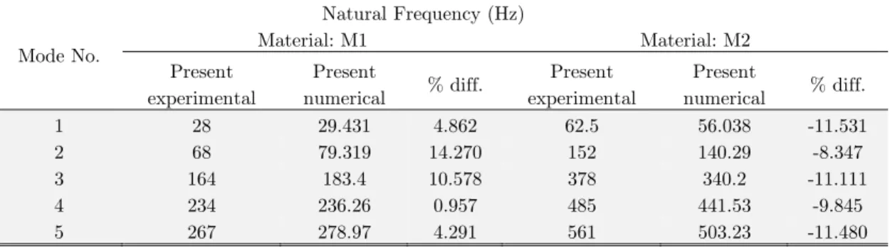
a lab scale experimental set-up as described in Section 4. The dimensions, lay-up scheme and mate-rial properties (M1 and M2) of the specimens are provided in Table 1. The natural frequencies are obtained for first five modes under CFFF boundary condition and shown in Table 5 along with the results computed using the current simulation model. It is evident from both the convergence and comparison study that the present numerical results are in good agreement with the established numerical values and present experimental results as well. The slight differences between the nu-merical and the experimentally obtained values can be attributed to the limitation in applying the perfect displacement boundary conditions on the plate as it is very difficult to replicate the exact conditions for multiple tests of the same specimen.
Mode No.
Natural Frequency (Hz)
Material: M1 Material: M2
Present experimental
Present
numerical % diff.
Present experimental
Present
numerical % diff.
1 28 29.431 4.862 62.5 56.038 -11.531
2 68 79.319 14.270 152 140.29 -8.347
3 164 183.4 10.578 378 340.2 -11.111
4 234 236.26 0.957 485 441.53 -9.845
5 267 278.97 4.291 561 503.23 -11.480
Table 5: Experimental validations of the natural frequencies of six layered woven glass/epoxy composite flat panel (M1) and four layered symmetric angle-ply carbon/epoxy flat panel (M2) under CFFF boundary condition.
5.1.3 Validation of the Acoustic Parameters
From the discussion in the previous sections, it is clear that the present simulation model yields valid results for the free vibrations response of the vibrating laminated composite flat panels under different boundary conditions. In this section, the mode shapes for each natural frequency of vibra-tion are extracted and used to compute the acoustic responses for the vibrating composite flat pan-els using coupled FEM/BEM approach in LMS Virtual.Lab environment. The sound power radiat-ed by the plate and the SPL at a particular location in the surrounding mradiat-edium are obtainradiat-ed to analyse the sound radiation characteristic. Initially, the radiated sound power values computed using the present scheme is compared with those reported in open literature. Then, the correspond-ing values of SPLs are also validated with the present experimentally obtained values uscorrespond-ing the lab-scale experimental set-up.
5.1.3.1 Validation of the Radiated Sound Power
and referred as Excitation-1 and Excitation-2 for the load acting at the central node and at a loca-tion (0.7m, 0.7m, 0) with reference to Figure 1, respectively. The sound power radiated by the plate is computed using the present formulation for the above two cases and shown in Figure 5 (a) and (b), respectively for the comparison with the reference values. It can be clearly seen that the sound power level computed using the present scheme match very well with the results reported in the reference over the entire range of frequencies considered.
0 200 400 600 800 1000 1200 1400 1600 0
10 20 30 40 50 60 70 80
Radiat
ed S
ound P
ower
(dB
)
Excitation Frequency (Hz) (a)
Jeyaraj (2010) Present numerical
0 200 400 600 800 1000
10 20 30 40 50 60 70 80
Radi
ated
Soun
d Po
wer (
dB)
Excitation Frequency (Hz) (b)
Jeyaraj (2010) Present numerical
Figure 5: Validation study of sound power level (a) Excitation type 1, (b) Excitation type 2.
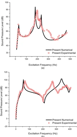
5.1.3.2 Experimental Validation of Sound Pressure Level
Laminated composite flat panels of M1 and M2 materials, as in Table 1, under CFFF boundary
ob-tained data. The comparison of the experimental and numerical results for SPL of the vibrating flat panel with M1 and M2 material properties are shown in Figure 6 (a) and (b), respectively. It is observed that in both the cases the present numerical values of SPL follow closely the experimental results (including the occurrence of peaks and depressions) up to the excitation frequency of 200 Hz, after which slight deviation is noticed. The reason for the deviation may be due to the limitations in applying displacement boundary condition on the structure and the absence of anechoic chamber during experimentation. It is also worthy to mention that the present numerical results have been computed by considering a modal damping ratio of 1% (which is the usual case for laminated com-posite structures) and that may not agree exactly with the damping occurring in the plates used for experimentation.
0 100 200 300 400 500
30 40 50 60 70 80 90 100
So
un
d
Pr
es
su
re
L
ev
el
(dB
)
Excitation Frequency (Hz) (a)
Present Numerical Present Experimental
0 100 200 300 400
-20 0 20 40 60 80 100 120
Sound
Pr
es
su
re
Le
ve
l (
dB
)
Excitation Frequency (Hz) (b)
Present Numerical Present Experimental
5.2.1 Influence of Structural Parameters on Sound Pressure Level and Radiated Sound Power
5.2.1.1 Influence of the Thickness Ratio
The influence of thickness ratio on the acoustic radiation behaviour of a four layered clamped sym-metric cross-ply [0ᵒ/90ᵒ]s laminated composite flat panel is investigated in this example. The plate
dimensions are taken as a = 0.4 m, b = 0.3 m and h is varied such that a/h = 5, 10, 40, 60, and 100. The laminated composite plate has two coincidence frequencies, which are a function of plate thick-ness and Young’s moduli of the material (Ohlrich and Hugin, 2004). The coincidence frequencies in Hz for each thickness value are (75.6, 378.03), (151.2, 756), (604.85, 3024.26), (907.28, 4536.4) and (1512.13, 7560.6), respectively. Therefore, a frequency range of 0-10,000 Hz is considered to observe the sonic and subsonic behaviour of plates. The variation of the radiation efficiency and the radiat-ed sound power with the excitation frequency for different values of thickness ratio is shown in Fig-ure 7 (a) and (b), respectively. It can be observed that the average radiation efficiency increases with increasing thickness ratio. For the thinnest plate (a/h=100), radiation efficiency is more as compared to the others due to reduced stiffness. This leads to shifting of natural modes of vibration to lower frequencies and higher coincidence frequencies in the considered frequency range. Also, it is worthy to note that the radiation efficiency exceeds 1 close to the first coincidence frequency and asymptotically decreases to 1 after the second coincidence frequency in most of the cases. The radi-ated sound power increases with increasing plate thickness ratio. A similar trend is observed for the sound pressure level in near and far-fields for modes (1,1) and (2,1) of the plates as shown in the SPL directivity plots in Figure 7(c) and (d), respectively.
0 1000 2000 3000 4000 5000
0.00 0.25 0.50 0.75 1.00 1.25 1.50 1.75 2.00 2.25 Ra di ati on Effi ci en cy
Excitation Frequency (Hz) a/h=5 a/h=10 a/h=40 a/h=60 a/h=100 (a)
0 2000 4000 6000 8000 10000
-20 0 20 40 60 80 100 R ad iated Sou nd Pow er (d B)
Excitation Frequency (Hz) a/h=5 a/h=10 a/h=40 a/h=60 a/h=100 (b) 40 50 60 70 80 90 100 0 30 60 90 120 150 180 210 240 270 300 330 40 50 60 70 80 90 100 R adi at ed Sound Pr essur e (dB ) a/h=5 a/h=10 a/h=40 a/h=60 a/h=100 (c) 45 60 75 90 105 0 30 60 90 120 150 180 210 240 270 300 330 45 60 75 90 105 Ra di at ed S ou nd P re ss ur e (d B) a/h=5 a/h=10 a/h=40 a/h=60 a/h=100 (d)
Figure 7: Influence of thickness ratio on the (a) Radiation efficiency; (b) Radiated sound power; (c) Sound pressure level directivity for mode (1,1) and (d) Sound pressure level directivity for mode (2,1)
5.2.1.2 Influence of the Aspect Ratio
To study the influence of aspect ratio (a/b) on the SPL and the sound power radiated in the
sur-rounding medium, a four layered anti-symmetric cross-ply [ 45ᵒ]2 laminated composite flat panel
under HHHH support condition has been considered. For the computation purpose the geometry of the panel is taken as a = 0.4 m, h = 0.01 m fixed and b is varied such that (a/b) = 0.5, 1, 1.5, 2, 2.5. The plate has the same coincidence frequencies (604.85, 3024.27) Hz for all of the aspect ratios. The plates’ mass and stiffness is affected by changing the aspect ratio leading to a change in the vibration energy of the plate. The radiation efficiency generally decreases with increasing aspect
ratio; a/b=0.5 case causes the maximum acoustic radiation onto the second coincidence frequency
and the same can be observed from Figure 8 (a). The average sound power level follows an increas-ing trend with decreasincreas-ing aspect ratio with the resonance peaks shiftincreas-ing to lower frequencies as shown in Figure 8(b). It is also worthy to note that the radiation efficiency exceeds unity indicat-ing that radiated acoustic power is more than the vibration energy of the plates.
0 1000 2000 3000 4000 5000 0.00
0.25 0.50 0.75 1.00 1.25 1.50 1.75 2.00 2.25
Radi
ait
on E
ffi
ci
enc
y
Excitation Frequency (Hz)
a/b=0.5 a/b=1 a/b=1.5 a/b=2 a/b=2.5
(a)
0 1000 2000 3000 4000 5000 -20
0 20 40 60 80 100
R
adi
at
ed
Sou
nd
Po
wer
(dB
)
Excitation Frequency (Hz)
a/b=0.5 a/b=1 a/b=1.5 a/b=2 a/b=2.5
(b)
Figure 8: Influence of aspect ratio on the (a) Radiation efficiency and (b) Radiated sound power of the laminated composite flat panel (HHHH four layered anti-symmetric cross-ply, [45ᵒ/-45ᵒ]2).
5.2.1.3 Influence of Modular Ratio
The effect of modular ratio on the acoustic emissions from a vibrating simply supported anti-symmetric angle-ply [±45ᵒ]2 rectangular laminated composite flat panel (a = 0.4 m, b = 0.3 m, and
h = 0.01 m) has been analysed. The radiation efficiency and the radiated sound power is obtained for E1/E2 = 5, 10, 15, 20, and 25 configurations. The first coincidence frequency is the same equal
oc-curring at almost same values of excitation frequency. The radiation efficiency crosses unity around the first natural frequency for all configurations of modular ratio and approaches unity after cross-ing the maximum value of second coincidence frequency.
0 1000 2000 3000 4000 5000
0.00 0.25 0.50 0.75 1.00 1.25 1.50 1.75 2.00
E1/E2=5 E1/E2=10
E1/E2=15 E1/E2=20
E1/E2=25
R
adi
ation
Effi
cien
cy
Excitation Frequency (Hz) (a)
0 1000 2000 3000 4000 5000 -30
-15 0 15 30 45 60 75 90
E1/E2=5 E1/E2=10 E1/E2=15 E1/E2=20 E1/E2=25
Radiat
ed
So
und
Po
wer
(d
B)
Excitation Frequency (Hz) (b)
Figure 9: Influence of modular ratio on the (a) Radiation efficiency and (b) Radiated sound power of the laminated composite flat panel (SSSS 4-layered anti-symmetric angle-ply, [45ᵒ/-45ᵒ]2).
5.2.1.4 Influence of Lay-Up Scheme
It is well known that, the lay-up scheme of any laminated composite structure significantly governs the stiffness and thus affects the vibration and sound radiation behaviour greatly. The effect of lamination scheme on the sound radiation characteristics of a vibrating laminated composite flat panel has been investigated by computing the SPL and radiated sound power of a plate (a = 0.4 m, b = 0.3 m, and h = 0.01 m) under CFFF support condition for different layup schemes. The SPL is obtained at a point 1m directly above the excitation location on the plate. It is observed from Fig-ure 10 that the SPL at the field point and the radiated sound power is greatly influenced by the lay-up scheme of the vibrating plate. It is worthy to note that, over the entire frequency range the
plate exhibits similar sound radiation behaviour for both the symmetric [45ᵒ/-45ᵒ]s and
anti-symmetric [45ᵒ/-45ᵒ]2 angle-ply lamination cases. However, there is a considerable difference
be-tween the sound radiation characteristics of symmetric [0ᵒ/90ᵒ]s and anti-symmetric [0ᵒ/90ᵒ]2
cross-ply laminations. It can also be seen that the peaks occur at higher frequencies for cross-cross-ply lamina-tions in comparison to the angle-ply schemes. However, the average SPL is lower for cross ply con-figuration compared to the angle ply concon-figuration with the minimum value for [0ᵒ/90ᵒ]2 case as
0 1000 2000 3000 4000 5000 0
10 20 30 40 50 60 70 80
[45/-45] s
[45/-45] 2
[0/90] s
[0/90] 2
R
adi
ated
Sound
Pressure
(dB)
Excitation Frequency (Hz) (a)
0 1000 2000 3000 4000 5000
-20 0 20 40 60 80 100
[45 /-45
]s [45
/-45 ]2 [0/90]
s
[0 /90
]2
R
aad
iated S
ound
P
owe
r (
dB)
Excitation Frequency (Hz) (b)
Figure 10: Influence of lay-up scheme on the (a) Radiated sound pressure and (b) Radiated sound power of the laminated composite flat panel (CFFF 4-layered).
Lay-up [45ᵒ/-45ᵒ]s [45ᵒ/-45ᵒ]2 [0ᵒ/90ᵒ]s [0ᵒ/90ᵒ]2 Average
SPL 60.125 59.424 58.496 58.364
Table 6: SPL values for different lay-ups.
5.2.1.5 Influence of Support Conditions
The number of constraints on the degrees of freedom at the support plays a significant role on the stiffness characteristics of any structure/structural component. The stiffness increases as the num-ber of constraints increases or the degree of freedom decreases and this may have a substantial ef-fect on the sound radiation characteristic of the structure. In this section, an anti-symmetric angle-ply [45ᵒ/-45ᵒ]2 rectangular (0.4 m×0.3 m×0.01 m) laminated composite flat panel has been
consid-ered for analysis. The first and the second coincidence frequencies are (604.85, 3024.27) Hz. The FFFF and CFFF configurations have many resonances before the first coincidence frequency. Therefore, the sound pressure level at a field point 1 m directly above the excitation location on the
plate and the radiated sound power is computed for four different support conditions (FFFF,
CCCC, SSSS and CFFF) in the frequency range 0-1000 Hz and presented in Figure 11 (a) and (b),
respectively. The influence of the number of constraints at the support is well reflected in the re-sults. It is observed that, over low excitation frequency range i.e., upto 1000 Hz, the sound power radiated from the vibrating plate decrease with increasing number of constraints at the support. However, the average sound power is the least for FFFF case followed in the increasing order by
CFFF, CCCC and SSSS and the same can be observed from the plot of sound power level for
0 200 400 600 800 1000 -15 0 15 30 45 60 75 90 105 Sound Pr es sure Lev el (dB )
Excitation Frequency (Hz) (a)
FFFF CCCC SSSS CFFF
0 200 400 600 800 1000 -40 -20 0 20 40 60 80 100 FFFF CCCC SSSS CFFF Radia ted Sound Power (d B)
Excitation Frequency (Hz) (b)
0 1000 2000 3000 4000 5000 -40 -30 -20 -10 0 10 20 30 40 50 60 70 80 90 100 R aad iat ed Soun d Powe r (d B)
Excitation Frequency (Hz)
FFFF CCCC SSSS CFFF
(c)
Figure 11: Influence of support condition on the (a) Sound pressure level at field point (0-1000 Hz); (b) Radiated sound power (0-1000 Hz) and (c) Radiated sound power of the laminated
composite flat panel (0-5000 Hz)(4-layered anti-symmetric angle-ply [45ᵒ/-45ᵒ]2).
5.2.2 Case Study: Vibro-Acoustic Response from Laminated Flat Panels of Various Composite Materials
In this section, a case study has been presented to compare the vibro-acoustic behaviour of the lam-inated flat panel of different composite materials those are widely used in their key areas of applica-tion. Four different composite materials namely, graphite-epoxy, boron-epoxy, kevlar-epoxy and glass-epoxy are considered for the present analysis and their properties are listed in Table 7.
Properties Graphite-epoxy
(Kumar et al., 2010)
Boron-epoxy (Kumar et al., 2010)
Kevlar-epoxy (Ku-mar et al., 2010)
Glass-epoxy (Daneshjou et al., 2007)
E1 1.37×10¹¹ Pa 2.04×10¹¹ Pa 76×109 Pa 38.6×10⁹ Pa
E2 = E3 8.9×10⁹ Pa 18.3×10⁹ Pa 5.5×10⁹ Pa 8.2×10⁹ Pa
ν12= ν23 = ν13 0.28 0.23 0.23 0.26
G12 = G13 7.1×10⁹ Pa 5.5×10⁹ Pa 2.4×10⁹ Pa 4.2×10⁹ Pa
G23 0.5×G12 0.5×G12 0.5×G12 0.5×G12
ρ 1600 kgm-3 2000 kgm-3 1460 kgm-3 1900 kgm-3
Table 7: Composite material properties of various laminated flat panels used for computation in the case study.
(0.125 m, 0.125 m ) from the lower left corner is considered. The SPL directivity pattern for modes (1,1) and (2,1), the radiation efficiency and the radiated sound power level values are computed for various composite materials using the present scheme and shown in Figure 12 (a)-(d), respectively. In general, the RMS values of a vibrating structure are considered to judge its suitability for a particular application. As evident from Figure 12 (a), (b), the SPL is the lowest for glass-epoxy corresponding to both of the modes. Also, the directivity patterns are of monopole and dipole nature in accordance with the mode shapes of (1,1) and (2,1) modes, respectively. The frequencies of first few resonance modes of glass-epoxy and kevlar-epoxy are lesser than the first coincidence frequencies which are around 700.2 Hz and 437.46 Hz, respectively. The radiation efficiencies of each material cross unity at the corresponding first coincidence frequency thereafter, following an asymptotic decrement to unity. The radiation efficiency curves for kevlar-epoxy and glass-epoxy are more fluctuating as compared to boron-epoxy and graphite-epoxy over the frequency range under consideration. This is due to the fact that, for glass-epoxy and kevlar-epoxy the longitudinal Young’s modulus (E1) is relatively low, which
leads to reduced stiffness. The same can also be observed from the plot of radiated sound power shown in Figure 12 (d). This may also be attributed to the higher values of E1/G12 ratio for these
materials (kevlar-epoxy and glass-epoxy) as compared to the relatively stiffer materials (graphite-epoxy and boron-(graphite-epoxy). However, the behaviour of graphite- (graphite-epoxy and boron-(graphite-epoxy is identical throughout the frequency range under consideration and the same can be observed from the radiation efficiency and sound power level plots shown in Figure 12 (c) and (d), respectively.
70 75 80 85 90 95 0 30 60 90 120 150 180 210 240 270 300 330 70 75 80 85 90 95 Ra dia ted S oun d P res su re ( dB ) Graphite-epoxy Boron-epoxy Kevlar-epoxy Glass-epoxy (a) 50 60 70 80 90 100 0 30 60 90 120 150 180 210 240 270 300 330 50 60 70 80 90 100 R adiat ed S ound P re ssu re (dB ) Graphite-epoxy Boron-epoxy Kevlar-epoxy Glass-epoxy (b)
0 1000 2000 3000 4000 5000 0.0 0.2 0.4 0.6 0.8 1.0 1.2 1.4 1.6 1.8 2.0 2.2 Radiat ion Ef ficienc y
Excitation Frequency (Hz)
Graphite-epoxy Boron-epoxy Kevlar-epoxy Glass-epoxy
(c)
0 1000 2000 3000 4000 5000 -40 -20 0 20 40 60 80 100 R adia ted S ou nd P ow er (dB )
Excitation Frequency (Hz)
Graphite-epoxy Boron-epoxy Kevlar-epoxy Glass-epoxy
(d)
Figure 12: Comparison of acoustic responses from the laminated flat panel of different composite materials (a) Sound pressure level directivity for mode (1,1); (b) Sound pressure level directivity for mode (2,1);
6 CONCLUSIONS
The vibration and acoustic responses of un-baffled laminated composite flat panels excited by har-monic point load and under various support conditions have been investigated in this article. The natural frequencies are computed with the help of a simulation model developed in ANSYS using APDL code. The results of modal analysis are exported to LMS Virtual.Lab environment, wherein the coupled vibro-acoustic responses of the vibrating panel are obtained using an indirect BEM. First, the free vibration responses obtained using the present simulation model are compared with the published numerical results and present experimentally determined values as well to test its validity. For the experimental analysis, the laminated composite plates were manufactured by hand lay-up technique and necessary steps were taken to ensure uniform thickness variation. The cantile-ver boundary condition was imposed on the plate by sandwiching it between the two bars and fully tightening them with the help of the nuts and bolts to closely match the corresponding constraints applied to the numerical model. Then, the ability and correctness of the present FEM/BEM scheme to compute the acoustic responses have been established by comparing the present responses with the numerical results available in open literature. The results are also compared with those obtained experimentally using the in-house experimental set-up. Finally, an extensive study has been per-formed to investigate the effect of geometrical parameters, support conditions and material proper-ties on the sound radiation characteristics of laminated composite flat panels. The sound pressure directivity in the medium, radiation efficiency and the radiated sound power of the vibrating plate is chosen as the acoustic response indicators. It is observed that the sound radiation behaviour of the laminated composite plate is greatly influenced by the lay-up scheme and number of constraints at the support. It is also noted that the acoustic responses increase with thickness ratio, decrease with aspect ratio and insignificantly affected by varying modular ratio. All materials exhibit dis-similar vibro-acoustic behaviour however, the sound radiation characteristics of the graphite- epoxy and boron-epoxy laminated plates are very close to each other. Among all the materials utilised for the present study, the sound pressure level for glass-epoxy is the least.
Acknowledgement
The authors of the article are thankful to Prof. Vishesh Ranjan Kar, Department of Design and Automation, School of Mechanical Engineering, VIT University, Vellore 632014, TN, India for providing access to LMS Virtual.Lab including a few more specific facilities.
References
Atalla, N., Nicolas, J., Gauthier, C., (1996). Acoustic radiation of an unbaffled vibrating plate with general elastic boundary conditions. Journal of Acoustical Society of America 99.
Atalla, N., Sgard, F., (2015). Finite element and boundary methods in structural acoustics and vibration, CRC Press, Taylor and Francis Group, Boca Raton, Florida, USA.
Cook, R. D., Malkus, D. S., Plesha, M. E., (2000). Concepts and applications of finite element analysis, 3rd edition, John Willy and Sons, Singapore.
Everstine, G. C., Henderson, F. M., (1990). Coupled finite element/boundary element approach for fluid–structure interaction, Journal of Acoustical Society of America 87:1938.
Holmstrom, F., (2001). Structure-acoustic analysis using BEM/FEM; Implementation in MATLAB, M.S. thesis, Lund University, Sweden.
Huang, M., Ma, X. Q., Sakiyama, T., Matuda, H., Morita, C., (2005). Free vibration analysis of orthotropic rectan-gular plates with variable thickness and general boundary conditions. Journal of Sound and Vibration 288:931–955. Jeyaraj, P., (2010). Vibro-acoustic behavior of an isotropic plate with arbitrarily varying thickness. European Journal of Mechanics - A/Solids 29:1088–1094.
Jeyaraj, P., Ganesan, N., Padmanabhan, C., (2009). Vibration and acoustic response of a composite plate with inher-ent material damping in a thermal environminher-ent. Journal of Sound and Vibration 320:322–338.
Jeyaraj, P., Padmanabhan, C., Ganesan, N., (2008). Vibration and Acoustic Response of an Isotropic Plate in a Thermal Environment. Journal of Vibration and Acoustics 130: 051005.
Kumar , B. R., Ganesan, N., Sethuraman, R., (2009). Vibro-acoustic analysis of functionally graded elliptic disc under thermal environment. Mechanics of Advanced Materials and Structures. 16:160–172.
Kumar, B. R., Ganesan, N., Sethuraman, R., (2010). Vibro-acoustic analysis of composite elliptic disc with various orthotropic properties. Journal of Composite Materials 44:1179–1200.
Li, S., Li, X., (2008). The effects of distributed masses on acoustic radiation behavior of plates, Applied Acoustics 69:272–279.
Nowak, L. J., Zieliński, T. G., (2015). Determination of the Free-Field Acoustic Radiation Characteristics of the Vibrating Plate Structures With Arbitrary Boundary Conditions. Journal of Vibration and Acoustics 137:051001–1– 051001–8.
Ohlrich, M., Hugin, C.T., (2004). On the influence of boundary constraints and angled baffle arrangements on sound radiation from rectangular plates. Journal of Sound and Vibration 277:405–418.
Park, J., Mongeau, L., Siegmund, T., (2003). Influence of support properties on the sound radiated from the vibra-tions of rectangular plates. Journal of Sound and Vibration 264:775–794.
Petrone, G., D’Alessandro, V., Franco, F., S. de Rosa, (2014). Numerical and experimental investigations on the acoustic power radiated by Aluminium Foam Sandwich panels. Composite Structures 118:170–177.
Putra, A., Thompson, D. J., (2010). Sound radiation from rectangular baffled and unbaffled plates. Applied Acous-tics 71:1113–1125.
Qiao, Y., Huang, Q., (2007). The effect of boundary conditions on sound loudness radiated from rectangular plates, Archives of Applied Mechanics 77:21–34.
Shojaeefard, M. H., Talebitooti, R., Ahmadi, R., Gheibi, M. R., (2014). Sound Transmission across Orthotropic Cylindrical Shells Using Third-order Shear Deformation Theory. Latin American Journal of Solids and Structures 11: 2039-2072.
Siemens LMS Virtual.Lab 13.5., (2015). Online help manual.
Tournour, M., Atalla, N., (1998). Vibroacoustic behavior of an elastic box using state-of-the-art FEM–BEM ap-proaches. Noise Control Engineering Journal 46.
Wu, J., Huang, L., (2013). Natural frequencies and acoustic radiation mode amplitudes of laminated composite plates based on the layerwise FEM. International Journal of Acoustics and Vibration 18:134–140.
Yin, X. W., Cui, H. F., (2009). Acoustic Radiation From a Laminated Composite Plate Excited by Longitudinal and Transverse Mechanical Drives. Journal of Applied Mechanics 76:044501.


![Figure 8: Influence of aspect ratio on the (a) Radiation efficiency and (b) Radiated sound power of the laminated composite flat panel (HHHH four layered anti-symmetric cross-ply, [45ᵒ/-45ᵒ] 2 )](https://thumb-eu.123doks.com/thumbv2/123dok_br/18887088.424079/16.808.105.721.424.656/figure-influence-radiation-efficiency-radiated-laminated-composite-symmetric.webp)
