Lat. Am. j. solids struct. vol.14 número8
Texto
Imagem


Documentos relacionados
As doenças mais frequentes com localização na cabeça dos coelhos são a doença dentária adquirida, os abcessos dentários mandibulares ou maxilares, a otite interna e o empiema da
Ousasse apontar algumas hipóteses para a solução desse problema público a partir do exposto dos autores usados como base para fundamentação teórica, da análise dos dados
Em contrapartida, para o caso do sistema de autoconsumo com armazenamento, o excesso de energia produzida é armazenada e posteriormente consumida quando a produção solar FV for
Molecular dynamics simulations of the ballistic Taylor test are used to explore correlation between the largest fragment mass and the impact energy of a projectile as well as a set
Finally, the effect of aspect ratio, thickness ratio, modular ratio and the lamination scheme on the acoustic radiation characteristics (sound pressure level and radiated sound
In the present research, according to the multilaminate framework for the prediction of fabric anisotropy effects, parameters related to the fabric effect of sandy soil particles
For ship collisions, the design criteria are based on limiting the accidental conse- quences of structural damage and environmental pollution, as well as ensuring that the main safety
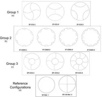
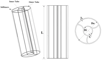
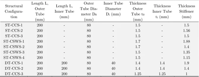
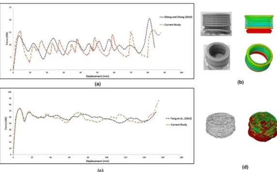
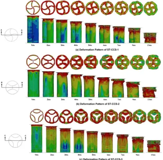
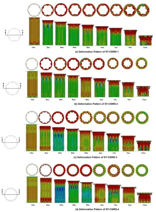
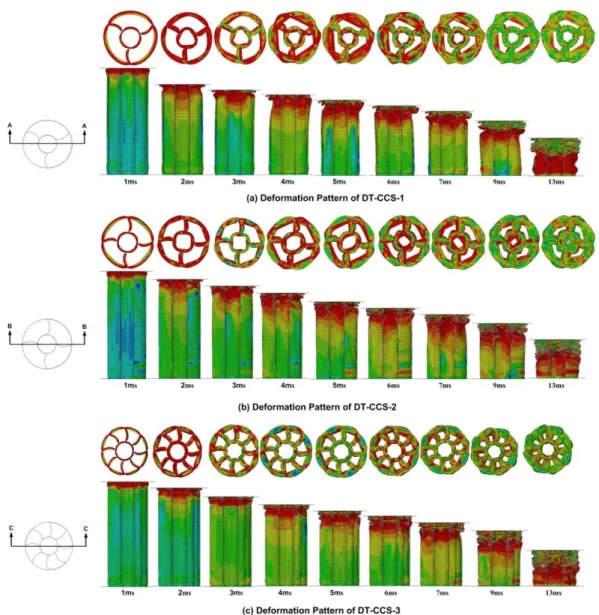
In this study, 3 groups of metallic tubes with the basic feature of curved stiffeners; distinct in other features such as equal number of cells in a single tube with stiffeners
