Abstract
In this paper vibration behavior of a fluid-conveying cracked pipe surrounded by a visco-elastic medium has been considered. During this work, the effect of an open crack parameters and flow velocity profile shape inside the pipe on natural frequency and critical flow velocity of the system has been analytically investigated. An explicit function for the local flexibility of the cracked pipe has been offered using principle of the fracture mechanics. Comparison between the results of the present study and the experimental data reported in the literature reveals success and high accuracy of the implemented method. It is demonstrated that the existence of the crack in the pipe, decreases the natural frequency and the critical flow velocity so that the system instability onsets at a lower flow velocity in comparison with the intact pipe. Results indicate that the flow ve-locity profile shape inside the pipe caused by the viscosity of real fluids, significantly affects the critical flow velocity of both intact and fluid-conveying cracked pipe. For instance, as the flow-profile-modification factor decreases from 1.33 to 1.015, the dimensionless critical flow velocity of intact clamped-clamped pipe increases from 5.45 to 6.24.
Keywords
Cracked Fluid-conveying Pipe, Vibration Analysis, Natural Fre-quency, Velocity Profile, Critical Flow Velocity.
Effect of Open Crack on Vibration Behavior of a Fluid-Conveying
Pipe Embedded in a Visco-Elastic Medium
NOMENCLATURE
, , , . . , constant time
crack depth mean fluid velocity
crack depth of the strip (in Figure 1) dimensionless fluid velocity
dimensionless crack depth coordinate
half width of crack axial coordinate
damping coefficient of foundation and transverse deflection Ghiyam Eslami a
Vahid A. Maleki b Mousa Rezaee b
a Department of Mechanical Engineering,
Ahar Branch, Islamic Azad University, Ahar, Iran.
b Faculty of Mechanical Engineering,
University of Tabriz, Tabriz, Iran.
a Corresponding author:
http://dx.doi.org/10.1590/1679-78251986
Latin American Journal of Solids and Structures 13 (2016) 136-154
NOMENCLATURE (continuation)
local flexibility dimensionless transverse deflection
Young module , left and right side of the crack transverse
deflection
external force coordinate
/ crack effect function
height of rectangular section flow-profile-modification factor
height of the strip (in Figure 1) dimensionless frequency
second moment of area dimensionless axial coordinate
stress intensity factor dimensionless crack location
equivalent torsional spring stiffness Dimensionless damping factor
, foundation constant, dimensionless , , , . . , constants
, Winkler stiffness, dimensionless local coordinate
length of pipe Poisson’s ratio
bending moment φ dimensionless parameter related to the effect of crack depth
and mass per unit length of pipe and
fluid natural frequency
dimensionless mass
, , . . , constants
, , matrix
and Outer and inner radius of the pipe
matrix
1 INTRODUCTION
Dynamic behavior of the fluid-conveying pipes has significant importance due to its extensive appli-cation in different industries such as petrol and gas transportation systems (Païdoussis 1998, Ibrahim 2010, Ghaitani and Esmaeili 2013). These pipes often lie on a foundation and would be cracked as a result of various internal and external loads while conveying fluid. So, analyzing the dynamic behavior of the cracked pipes would be practically important.
Latin American Journal of Solids and Structures 13 (2016) 136-154
Having no fluid inside,
Filled with fluid without flow (zero flow velocity)
Having fluid flow inside (fluid-conveying pipe).
There are fairly large amount of researches dedicated to the first two groups; Liu et al. (2003) examined the stability of thin-walled pipe due to circumferential cracks analytically and experimen-tally based on the coupled-response measurements. Ye et al. (2010) investigated the vibration behav-ior of the cracked pipe in the absence of the fluid flow using the finite element method. Their results show that the presence of the crack in the pipe reduces the natural frequency, and its effect on the upper natural frequencies is more than the lower ones. Murigendrappa et al. (2004a; 2004b) studied the vibration behavior of the cracked pipe theoretically and experimentally. In their works, the crack has been considered as a torsional spring and the transfer matrix method with Rayleigh’s quotient has been used for vibration analysis. Naniwadekar et al. (2008) developed an experimental method for crack detection based on changing the natural frequency and presented a numerical method to analyze the vibration behavior of a straight horizontal steel hollow pipe filled with an incompressible fluid (without flow).
In contrast to the first two groups, there are fairly limited amount of investigation about the vibration behavior of the cracked fluid-conveying pipes (third group). Yoon and Soo are two research-ers that have contributed in most papresearch-ers published about vibration behavior of the fluid-conveying cracked pipes. They investigated the effects of the open crack parameters and the moving mass on the dynamic behavior of simply supported pipe conveying fluid using Timoshenko beam model. Nu-merical methods based on the transfer matrix have been preferred in their works (Son, Lee et al. , Yoon and Son 2004, Yoon, Son et al. 2004, Yoon and Son 2005, Yoon and Son 2006, Son, Cho et al. 2007, Yoon and Son 2007, Yoon, Son et al. 2007, Son and Yoon 2008, Son, Yoon et al. 2010). So, available research in literature did not consider the effects of the crack parameters on the critical flow velocity which is our main objective in this paper.
In present paper the vibration behavior of the cracked fluid-conveying pipe is examined via Euler-Bernoulli beam model focusing on natural frequency and critical flow velocity. Also, in order to have a more realistic model, the surrounding elastic medium is modeled via a visco-elastic foundation. Our study is carried out through an analytical method. The crack is considered using a massless torsional spring. An explicit function for obtaining the local flexibility of the cracked pipe is presented using the theory of fracture mechanics. Also, we demonstrate that how the fluid flow velocity profile would influence the critical flow velocity of the system.
2 LOCAL FLEXIBILITY OF THE CRACKED PIPES
Latin American Journal of Solids and Structures 13 (2016) 136-154 The additional strain energy due to the crack can be considered in the form of a flexibility coef-ficient expressed in terms of the stress intensity factor, which can be derived by Castigliano’s theorem in the linear elastic range. Therefore, the local flexibility in the presence of the crack is defined by (Zou et al. 2003):
(1)
where
E
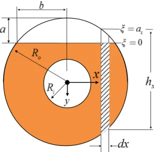
is Young module, υis Poisson’s ratio, and are the crack dimensions as shown in Figure1. KΙis the stress intensity factor corresponding to the first fracture mode due to the bending moment
M.
Figure 1: Cross section of the cracked pipe.
It is seen from Eq. (1) that the local flexibility depends on the stress intensity factor. In order to calculate the stress intensity factor for the cracked pipes, consider a small vertical rectangular strip,
having a small cross-sectional width dx and height with an arbitrary offset distance x, as shown
in Figure 1. In Ref. (Tada, Paris et al. 2000) the stress intensity factor for a rectangular section is presented as:
√ / (2)
where, ais the crack depth, Ι and
h
are the second moment of area and height of the rectangularcross-section, respectively and / is a mathematical function of crack dimension. Employing Eq.
(2) for the rectangular strip shown in Figure 1 leads:
/ (3)
x
Latin American Journal of Solids and Structures 13 (2016) 136-154
in which, is local coordinate which varies from to swiping the crack depth in the given
strip, and / is defined as (Tada et al. 1973):
tan . . sin
cos (4)
Substituting Eq. (3) into Eq. (1) leads to:
(5)
The equivalent rotational spring stiffness, , is defined as (Dimarogonas and Papadopoulos, 1983):
(6)
Taking into account the coordinate system illustrated in Figure 1, and calculated as:
(7)
(8)
and the upper boundary of the crack, , can be expressed as:
. (9)
By defining the dimensionless variables;x x Ro , hx hx Ro , b b Ro ,ax ax Ro and
αc a Ro , the dimensionless form of Eqs. (7)- (9) becomes:
̅ (10)
(11)
̅ . (12)
Substitution of Eqs. (10)-(12) into Eq. (5) leads:
̅ ̅ ̅ ̅ ̅ (13)
where ̅ ⁄ . For the flexibility coefficient, the dimensionless form introduced as:
̅ (14)
Latin American Journal of Solids and Structures 13 (2016) 136-154
̅ ̅ ̅ ̅ ̅ (15)
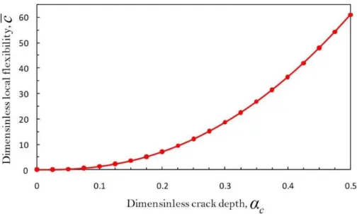
Eq. (15) represents an integral form for the local flexibility of the cracked pipes. This integral
expression is only a function of the dimensionless crack depth,αc a Ro. By numerical integration of
Eq. (15) and fitting an appropriate curve to the numerical values of c and then using the least square
method, an explicit expression for the dimensionless flexibility coefficient of the cracked pipe is ob-tained as:
̅ . . . . .
. . . .
. . (16)
It should be noted that according to the main assumption in the fracture mechanics, Eq. (16) is
satisfied up to middle of the pipe wall thickness i.e. ⁄ .
This explicit function may be applied for any pipe with specified mechanical properties and
geo-metrical dimensions. Considering Eqs. (16) and (14), the equivalent stiffness of the cracked pipe, Kt
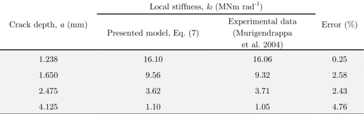
is calculated straightforwardly from Eq. (6). In order to verify the accuracy of this model, the
pre-dicted values of Ktand the experimental results reported by Murigendrappa et al. (2004) for a cracked
pipe with a parametersRo 16.5mm, Ri 10mm, E 65GPa and ν0.33 have been
compared in Table 1. The comparison shows that there is a good agreement between the equivalent stiffness obtained from the proposed method and the experimental data. So, the maximum difference between the predicted results and the experimental data of Murigendrappa et al. (2004) is less than 5%.
Crack depth, a (mm)
Local stiffness, kt (MNm rad-1)
Error (%) Presented model, Eq. (7)
Experimental data (Murigendrappa
et al. 2004)
1.238 16.10 16.06 0.25
1.650 9.56 9.32 2.58
2.475 3.62 3.71 2.43
4.125 1.10 1.05 4.76
Table 1: The local stiffness due to crack, Comparison between the calculated results and the experimental data of Murigendrappa et al. (2004).
Latin American Journal of Solids and Structures 13 (2016) 136-154
Figure 2: Effect of the crack depth on the dimensionless local flexibility coefficient.
3 MATHEMATICAL MODEL
Figures 3a and 3b illustrate schematically a fluid-conveying cracked pipe resting on a visco-elastic foundation and its corresponding mathematical model, respectively. Using the Euler-Bernoulli theory, the modified governing equation of motion for the uniform fluid-conveying
pipe which is subjected to an external force,Fe x t , can be written as (Guoa et al. 2010):
, , , , (17)
where
m
p andm
f are the mass per unit length of pipe and fluid, respectively. t stands for time,is axial coordinate, W (X , t) and
E
Ι
are the transverse deflection and the flexural stiffness of thepipe, respectively.
α
denotes a dimensionless parameter named as the flow-profile-modification factordependent on fluid velocity profile inside pipe. Considering the power-law profile for the time-average flow velocity profile (Streeter et al. 1998)as:
α can be determined by (Guoa et al. 2010):
2
5
1
1
2
2
n
n
n
Latin American Journal of Solids and Structures 13 (2016) 136-154 Figure 3: (a) Schematic view of the cracked clamped-clamped pipe, (b) Mathematical model.
Where n is dependent on the Reynolds number. The well-known one-seven power-law velocity profile introduced by Prandtl can be achieved for n=7 that is valid for the smooth-wall circular pipes
in the range 3×10³ Re 3×10⁵ (Re denotes the Reynolds number). Also, n=4 and n=5 provide the
velocity profile of a rough-wall circular pipe based on the experiments of Nikuradse. For n=7, α
=1.020; and for n=4 and n=5, α≈1.037–1.055. We will discuss more about the impact of α on the
vibration behavior of the intact and cracked fluid-conveying pipes in subsection 6.2.
In the present work, the external force related to the visco-elastic foundation modeled using
two-parameter Kelvin-Voigt model. Based on this model
F
ext can be written as:, ,
, (18)
where, K m and
C
stand for the Winkler stiffness constant and the damping coefficient of thevisco-elastic foundation, respectively. Ksis an additional parameter defining the foundation, usually termed
Latin American Journal of Solids and Structures 13 (2016) 136-154
, , , , ,
, (19)
It is assumed that the solution of Eq. (19) is:
, (20)
where
W X
( )
and ωindicate the amplitude and natural frequency, respectively. The dimensionlessvariables are defined as:
, , , , ,
, ,
(21)
Substituting Eq. (20) into Eq. (19) and using the above dimensionless variables, Eq. (19) can be rewritten as follows:
√ (22)
The solution of the Eq. (22) is:
(23)
where
A
and λ are constants. Substituting this expression in Eq. (22) leads to the followingcharac-teristic equation:
√ (24)
The Eq. (24) is a quartic polynomial equation, which has generally four complex roots (consider a typical real root as a complex root with zero imaginary part). The explicit algebraic formulas for a general solutions of Eq. (24) are expressed as (Persidis 2007):
, , ,
(25)
where the parameters p1, p2 and p3 which depend on the dimensionless natural frequency β, have
been defined in appendix. The general solution of Eq. (22) is
(26)
In which Ai, i 1, 2, 3, 4are unknown constants and will be obtained by applying the boundary
Latin American Journal of Solids and Structures 13 (2016) 136-154
4. FREQUENCY EQUATION
Consider the corresponding mathematical model of the cracked pipe conveying fluid resting on a visco-elastic medium as shown in Figure 3b. For analyzing the free vibration of the cracked pipe, the entire pipe is divided from the cracked section into the two pipe segments. The crack is represented by a torsional mass-less spring that its stiffness was calculated previously in section 2. The two pipe segments can be treated separately. The equations of motion for two mentioned intact segments are obtained from Eq. (26) as follows:
(27)
(28)
where wL ζ and w R ζ are the vibration mode of each segment in the left and the right side of
the crack, respectively. These vibration modes have eight unknown constants Ai, i 1, 2, ..., 8, which
can be obtained by applying both boundary conditions and compatibility conditions at the crack location. The compatibility of displacement, moment and shear force of both segments at the
dimen-sionless crack location (i.e. ζζc), are respectively given by:
, , (29)
and the discontinuity in the slope of the pipe at the cracked location may be implemented as
φ . (30)
where φ is the dimensionless parameter indicating the effect of crack depth. General boundary
conditions can be applied for the present model. In this paper, clamped–clamped supported pipe is considered. Thus the four boundary conditions may be written as:
| , , | , . (31)
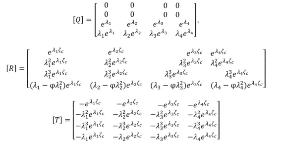
Substituting Eqs. (27) and (28) into the boundary conditions Eq. (31) and into the compatibility conditions Eqs. (29) and (30), gives a set of eight homogeneous linear algebraic equations for the eight unknown constants Ai, i 1, 2, ..., 8as follows:
(32)
where
Latin American Journal of Solids and Structures 13 (2016) 136-154 ,
φ φ φ φ
(33)
The system of equations (32) has the nontrivial solution if and only if the determinant of the coefficients becomes zero. So the characteristic equation of the system will be:
|Δ| , , , , , , , , (34)
Now, by solving the Eq. (34), the dimensionless natural frequency, , can be obtained.
5 VALIDATION
To the best knowledge of the authors, there is no analytical or experimental result in the literature for the vibration analysis of a problem that is completely the same of one stated here. So in order to validate the aforementioned theoretical model and analytical procedure, we use available data for a similar problem. For instance, comparison made between the present work results and the experi-mental data of Mahjoob and Shahsavari (2007) for the case of a clamped-clamped cracked pipe
con-veying fluid without foundation (i.e. km ks c 0). The implemented mechanical and geometrical
properties required to calculate the results are listed in Table 2. The maximum difference between the experimental data of Mahjoob and Shahsavari (2007) and the present model results are 0.29%, 0.47% and 0.45% for the first, second and third natural frequencies, respectively (Table 3). Therefore, this comparison indicates an excellent agreement between present study and the experimental data.
Pipe Fluid
Parameter E ρp Ri Ro l mf ρf
Dimension GPa kg m-3 mm mm m kg m-1 kg m-3
Value 210 7800 8 10.5 1 0.02 980
Latin American Journal of Solids and Structures 13 (2016) 136-154 Flow
velocity, m s-1
Crack depth,
mm
Natural frequencies (Hz)
Present analytical method
Experimental Data (Mahjoob and Shahsavari 2007)
Error (%)
1
f f2 f3 f1 f2 f3 f1 f2 f3
1 Intact pipe 118.94 327.87 642.75 118.97 327.98 643.00 0.10 0.03 0.06
1 118.92 327.83 642.48 118.72 326.46 639.60 0.16 0.42 0.45
2 118.82 327.68 641.00 118.47 326.22 639.35 0.30 0.45 0.29
5 Intact pipe 118.93 327.81 642.74 118.94 327.92 642.9 0.01 0.03 0.02
1 118.91 327.82 641.36 118.72 326.39 639.49 0.16 0.44 0.29
2 118.81 327.67 640.79 118.47 326.15 639.24 0.29 0.47 0.24
Table 3: Natural frequencies of the clamped-clamped fluid-conveying cracked pipe forζc 0.4. Comparison between results of present analytical method and the experimental data of
Mahjoob and Shahsavari (2007)for various flow velocity.
6 RESULTS AND DISCUSSION
Having insured the accuracy of the present model, it is used to examine the vibration behavior of the cracked pipe conveying fluid resting on a visco-elastic foundation. The elastic, shear and damping
constants used for the foundation as a Kelvin–Voigt model are respectively Km=3.08 MPa, Ks=12550
kN and C=3110 Pa.s as given in (Gerolymos and Gazetas 2006, Younesian et al. 2012). In all
numer-ical calculations, the flow-profile-modification factor, α, has been taken 1.33 except where it has been
clearly specified.
6.1 Effect of the Crack Parameters
Figure 4, illustrates first natural frequency of the cracked pipe conveying fluid as a function of
the dimensionless crack location, for three different values of αc 0 .0 2 5,αc 0.25 and αc 0.4,
where the foundation parameters were ks km 0.01 and
c
0
. It is found that the crack parametersaffect the vibration behavior of the cracked pipe. It is obvious that the frequencies of a system gen-erally decrease due to the crack. Results show that when the crack location approaches to the fixed ends of the pipe, the effect of the crack on the frequency reduction is increased. This tendency is intensified with an increase in the crack depth. Also, as seen in Figure 4, for the crack located at
c
ζ 0.225and ζc0.775, there is no reduction in the first natural frequency. Indeed, the mentioned
locations are the inflection points for the first vibration mode of a clamped-clamped pipe. In these
locations, the second derivation of the deflection function is equal to zero ( 2 ( ) 2
0
d W X dX = ) causing
Latin American Journal of Solids and Structures 13 (2016) 136-154
the crack located at ζc0.225 and ζc0.775 has no effect on the first natural frequency. The same
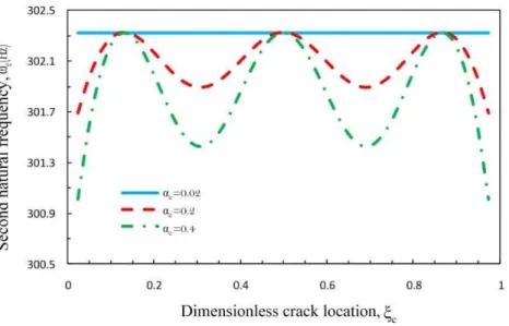
behavior is observed for the alteration of the second natural frequency shown in Figure 5.
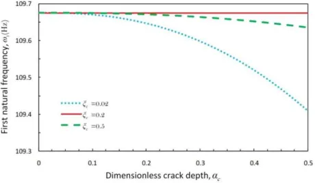
Figure 6 presents the natural frequency of the cracked pipe for the first mode as a function of the
dimensionless crack depth for different values of ζc. When the crack depth,ac, increases, the local
flexibility of the pipe reduces according to Eq. (7) causing reduction in the natural frequency.
Figure 4: First dimensionless natural frequency of the fluid-conveying cracked pipe as a function of the dimensionless crack location.
Latin American Journal of Solids and Structures 13 (2016) 136-154 Figure 6: First natural frequency of the fluid-conveying cracked pipe.
6.2 Effect of the Flow Velocity
As seen from frequency equation (Eq. 34), the natural frequency of the cracked pipe conveying fluid in visco-elastic medium depends on the fluid flow velocity. Figure 7 shows the natural frequency of the intact pipe versus the dimensionless flow velocity for the first and second vibration modes. For
the clamped-clamped intact pipe, the dimensionless critical flow velocity is Intact 2
cr
u π(Doare and
Langer 2002). As it is obvious from the Figure 7, when the flow velocity increases, the pipe natural
frequency decreases smoothly until it completely vanishes for u=2π. This equals to the lowest critical
flow velocity that causes instability in the system. It is worth to note that u=2π corresponding to the
mean flow velocity of U=498.5 m/s. This high velocity for a typical compressible fluid corresponds to
Mach numbers greater than unit (Ma>1). Since for Ma>0.3, the compressibility should be taken into
account, the present results for the critical flow velocity are not valid for the compressible fluids.
Latin American Journal of Solids and Structures 13 (2016) 136-154
Experiments of Nikuradse revealed that fluid velocity profile in the circular pipes changes based on the quality of wall roughness. In order to take into account the effect of the mentioned change in the velocity profile, on vibration behavior of the fluid-conveying pipes, Guoa et al. (2010) derived a
modified equation of motion for the pipe. The expression, α, appears in the centrifugal term of the
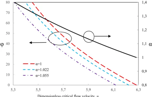
modified equation (Eq. 17). As depicted in Figure 8, the flow-profile-modification factor would influ-ence the critical flow velocity of both intact and cracked fluid-conveying pipe. As Guoa et al. (2010)
indicated, when α decreases from 1.33 to 1.015, the velocity profile in the pipe cross section tends to
a typical turbulent flow profile. This trendency corresponds to increase in critical flow velocity ac-cording to Figure 8. Thus it can be deduced that the instability in a typical fluid-conveying pipe would be delayed in turbulence regime in comparison with the laminar one. For an instance, the dimensionless critical flow velocity of intact pipe increases from 5.45 to 6.24 as the flow-profile-mod-ification factor decreases from 1.33 to 1.015.
In the case of a cracked fluid-conveying pipe, the crack depth influences significantly the impact of flow-profile-modification factor on critical flow velocity. An interesting behavior observed in Figure 8 is about the effect of crack and its depth on the system instability. As it is seen, existence of a crack on the pipe causes the instability in a lower fluid flow velocity and this effect is intensified
propor-tionally with crack depth for a given crack location (c 0.01 in Figure 8). This behavior shows that
the crack and the instability would practically reinforce each other in a pipe system causing its de-struction.
Figure 8: Flow-profile-modification factor influences the impact of crack depth, φ, on the critical flow velocity, ucr for c 0.01 (left vertical axis). Also, it affects the critical flow velocity of an intact
clamped-clamped pipe (right vertical axis).
0,8 0,9 1 1,1 1,2 1,3 1,4 0 10 20 30 40 50 60 70 80
5,3 5,5 5,7 5,9 6,1 6,3
α
φ
Dimensionless critical flow velocity, ucr
α=1
α=1.022
Latin American Journal of Solids and Structures 13 (2016) 136-154 6.3 Effect of the Visco-Elastic Foundation
Figure 9 shows the effect of the foundation parameters on the critical velocity as a function of the dimensionless damping factor, c, for the different foundation parameters. The comparison is made for
the crack parameters αc0.2and ζc 0 .1. As seen in Figure 9, divergence instability for the first
mode occurs when ucr≃1.01 but by increasing the dimensionless damping parameter of the
visco-elastic foundation, c and/or decreasing the dimensionless stiffness parameter, ks, the instability of the
pipe takes place at a lower flow velocity.
Figure 10 shows the first three dimensionless frequencies of the cracked pipe as a function of the
dimensionless parameters kmwhere
c
0.01
,u
0
. The results indicate that any augmentation inthe foundation stiffness constant is followed by increasing the natural frequencies. This means that increasing the elastic constant makes the pipe stiffer. Also, effect of the foundation stiffness is more pronounced in the lower natural frequencies than the upper ones.
Figure 9: Variation of the dimensionless critical flow velocity of the clamped-clamped cracked pipe against the dimensionless damping factor for different values of the dimensionless stiffness, ks.
Figure 10: Effect of the foundation stiffness, km, on the first three natural frequencies
Latin American Journal of Solids and Structures 13 (2016) 136-154
7 CONCLUSION
In the current study, the vibration behavior of a cracked pipe conveying fluid resting on a visco-elastic foundation was investigated analytically. A new approach for calculating the local flexibility caused by a crack was developed. The mentioned approach is applicable for various pipes with differ-ent mechanical properties. Comparison between the analytical results and available experimdiffer-ental data in literature shows good agreement for a wide range of the crack parameters.
The results indicate that increasing the crack depth improves the flexibility, and therefore the local stiffness reduces at the crack location. This leads to reduction in the both natural frequency and critical flow velocity of the cracked pipe system. This feature can be utilized for crack detection based on the vibration analysis. Also, when the crack location approaches to the fixed ends of the pipe, reduction in the natural frequency becomes more considerable. Furthermore, the results show that a decrease in the natural frequency reduces when the crack gets closer to the inflection points until it completely vanishes in the inflection points.
The fluid flow inside the pipe and its profile shape influences the natural frequency of the cracked pipe significantly. Moreover, the crack decreases the critical flow velocity so that the system instability onsets at a lower flow velocity.
Acknowledgement
The authors would like to appreciate Ahar Branch, Islamic Azad University for the financial support of this research, which is based on a research project contract.
References
Ansari, M., E. Esmailzadeh and D. Younesian (2011). "Frequency analysis of finite beams on nonlinear Kelvin–Voight foundation under moving loads." Journal of Sound and Vibration 330(7): 1455-1471.
Bai, Q., X. Shang and L. Yin (2013). "Free Vibration Analysis of Elastic Pipe with Crack Defects." Journal of Applied Sciences 13: 5440-5445.
Basu, D. and N. S. V. Kameswara Rao (2013). "Analytical solutions for Euler-Bernoulli beam on visco-elastic founda-tion subjected to moving load." Internafounda-tional Journal for Numerical and Analytical Methods in Geomechanics 37(8): 945-960.
Guoa,C.Q, C.H. Zhanga and M.P. Paidoussis (2010). "Modification of equation of motion of fluid-conveying pipe for laminar and turbulent flow profile." Journal of Fluids and Structures 26: 793–803.
Dimarogonas, A. D. (1996). "Vibration of cracked structures: a state of the art review." Engineering fracture mechanics 55(5): 831-857.
Dimarogonas, A. S. and C. A. Papadopoulos (1983). "Vibration of cracked shafts in bending." Journal of Sound and Vibration 91(4): 583-593.
Doare, O. and E. D. Langer (2002). "local and global instability of fluid-conveying pipes on elastic foundation." Journal of Fluids and Structures 16(1): 1-14.
Latin American Journal of Solids and Structures 13 (2016) 136-154 Gerolymos, N. and G. Gazetas (2006). "Winkler model for lateral response of rigid caisson foundations in linear soil." Soil Dynamics and Earthquake Engineering 26(5): 347-361.
Ghaitani, M. M. and H. A. Esmaeili (2013). "Vibration response of oil pipes embedded in viscous fluid using DQM". 2nd International Conference on Emerging Trends in Engineering & Technology. College of Engineering, Teerthanker Mahaveer University.
Hu, J.-S., W.-Y. Sun and J. Zhou (2011). "Vibration analysis and crack identification of a cantilever pipe with a circumferential part-through crack." Journal of Vibration and Shock 4: 008.
Ibrahim, R. A. (2010). "Overview of Mechanics of Pipes Conveying Fluids—Part I:Fundamental Studies" Journal of Pressure Vessel Technology 132: 034001-034031.
Kargarnovin, M. H., D. Younesian, D. J. Thompson and C. J. C. Jones (2005). "Response of beams on nonlinear viscoelastic foundations to harmonic moving loads." Computers & Structures 83(23-24): 1865-1877.
Kumar, C. and V. Rastogi (2010). "A brief review on dynamics of a cracked rotor" International Journal of Rotating Machinery 2009.
Liu, D., H. Gurgenci and M. Veidt (2003). "Crack detection in hollow section structures through coupled response measurements." Journal of sound and vibration 261(1): 17-29.
Liu, D., T. Zhu, J. Zhou And X.-G. Zhao (2012). "Study on Vibration Characteristics of a Pipe with a Crack" China Offshore Platform 2: 007.
Mahjoob, M. J. and a. A. Shahsavari (2007). A Vibration-Based Damage Detection Method for Pipes Conveying Fluid. 48th AIAA/ ASME/ ASCE/ AHS/ ASC Structures, Structural Dynamics, and Materials Conference. Honolulu, Ha-waii.
Murigendrappa, S. M., S. K. Maiti and H. R. Srirangarajan (2004). "Experimental and theoretical study on crack detection in pipes filled with fluid." Journal of Sound and Vibration 270(4-5): 1013-1032.
Murigendrappa, S. M., S. K. Maiti and H. R. Srirangarajan (2004). "Frequency-based experimental and theoretical identification of multiple cracks in straight pipes filled with fluid." NDT & E International 37(6): 431-438.
Naniwadekar, M. R., S. S. Naik and S. K. Maiti (2008). "On prediction of crack in different orientations in pipe using frequency based approach." Mechanical Systems and Signal Processing 22(3): 693-708.
Nguyen, V.-H. and D. Duhamel (2008). "Finite element procedures for nonlinear structures in moving coordinates. Part II: Infinite beam under moving harmonic loads." Computers & Structures 86(21-22): 2056-2063.
Païdoussis, M. P. (1998). Fluid-Structure Interactions. Fluid-Structure Interactions, Academic Press. Persidis, S. (2007). Mathematical Handbook. ESPI, ATHENS, ESPI PUBLISHING.
Sinha, J. K., M. I. Friswell and S. Edwards (2002). "Simplified Models for the Location of Cracks in Beam Structures Using Measured Vibration Data." Journal of Sound and Vibration 251(1): 13-38.
Son, I.-S., S.-P. Lee, J.-K. Lee and D.-S. Bae "Dynamic Behavior of Forced Vibration of Elastically Restrained Pipe Conveying Fluid with Crack and Concentrated Mass."
Son, I., J. Cho and H. Yoon (2007). "Effects of Attached Mass on Stability of Pipe Conveying Fluid with Crack." Transactions of KSNVE 17(10): 1002-1009.
Son, I. and H. Yoon (2008). "Dynamic Stability of Elastically Restrained Cantilever Pipe Conveying Fluid with Crack." Transactions of KSNVE 18(2): 177-184.
Son, I. S., H. I. Yoon, S. P. Lee and D. J. Kim (2010). "Effects of Tip Mass on Stability of Rotating Cantilever Pipe Conveying Fluid with Crack." International Journal of Modern Physics B 24(15n16): 2609-2614.
Streeter, V. L., E. B. Wylie and K. W. Bedford (1998). Fluid mechanics, WCB, McGraw-Hill.
Latin American Journal of Solids and Structures 13 (2016) 136-154
Xie, Y. (1998). "A theory on cracked pipe." International journal of pressure vessels and piping 75(12): 865-869. Ye, J., Y. He, X. Chen, Z. Zhai, Y. Wang and Z. He (2010). "Pipe crack identification based on finite element method of second generation wavelets." Mechanical Systems and Signal Processing 24(2): 379-393.
Yoon, H.-I. and I.-S. Son (2004). "Dynamic behavior of cracked pipe conveying fluid with moving mass based on Timoshenko beam theory." KSME international journal 18(12): 2216-2224.
Yoon, H.-I. and I.-S. Son (2005). "Influence of tip mass on dynamic behavior of cracked cantilever pipe conveying fluid with moving mass." Journal of mechanical science and technology 19(9): 1731-1741.
Yoon, H.-I. and I.-S. Son (2006). "Dynamic behavior of cracked simply supported pipe conveying fluid with moving mass." Journal of Sound and Vibration 292(3-5): 941-953.
Yoon, H.-I. and I.-S. Son (2007). "Dynamic response of rotating flexible cantilever pipe conveying fluid with tip mass." International journal of mechanical sciences 49(7): 878-887.
Yoon, H., I. Son and S. Ahn (2007). "Free Vibration Analysis of Euler-Bernoulli Beam with Double Cracks." Journal of Mechanical Science and Technology 21: 476-485.
Yoon, H. I., I. S. Son and J. T. Jin (2004). "A study on dynamic behavior of simply supported fluid flow pipe with crack and moving mass."
Younesian, D., S. R. Marjani and E. Esmailzadeh (2012). "Nonlinear vibration analysis of harmonically excited cracked beams on viscoelastic foundations." Nonlinear Dynamics 71(1-2): 109-120.
Yumin, H., Y. Junjie and H. Zhengjia (2011). "Research on Quantitative Identification of Pipe Crack Based on Vibra-tion." Measuring Technology and Mechatronics Automation (ICMTMA), 2011 Third International Conference on, IEEE.