Brazilian Microwave and Optoelectronics Society-SBMO received 15 May 2010; revised 20 May 2010; accepted 5 Oct 2010 Brazilian Society of Electromagnetism-SBMag © 2010 SBMO/SBMag ISSN 1516-7399
An Efficient Routing Scheme to Reduce
Packet Loss in All Optical Networks
Amit Kumar Garg1, R S Kaler2
1School of Electronics and Communication Engg, Shri Mata Vaishno Devi University
(J&K), India
2Department of Electronics and Communication Engineering, Thapar University,
Patiala, Punjab, India
Abstract— Optical burst switching (OBS) is a promising technology for the next generation optical Internet. A buffer-less OBS network can be implemented using ordinary optical communication equipment without the need for either wavelength converters or optical memories. However, OBS networks suffer from a relatively high blocking probability, a primary metric of interest, because of contention. In this paper, an efficient deflection routing scheme for buffer-less OBS networks has been proposed in order to reduce blocking probability (Packet loss) caused by Offset Time (OT) and burst contention. Simulation results have shown that the proposed scheme reduces blocking probability effectively and also it maintains a reasonable end-to-end delay for each burst. Thus, it improves the overall network performance by reducing the burst blocking probability effectively.
Index Terms— Blocking probability, Contention, OBS, Offset-time
I. INTRODUCTION
Brazilian Microwave and Optoelectronics Society-SBMO received 15 May 2010; revised 20 May 2010; accepted 5 Oct 2010 Brazilian Society of Electromagnetism-SBMag © 2010 SBMO/SBMag ISSN 1516-7399
II. STATE OF THE ART IN BURST BLOCKING ISSUE
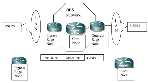
A major issue in OBS networks is wavelength contention which is the main cause of burst losses; this may degrade considerably the performance of such networks. A contention arises when two or more bursts intend to take the same output fiber, on the same wavelength, at the same time. Hence, various studies have already been made to resolve wavelength contention in OBS networks. Buffering, wavelength conversion and deflection are technologies that can be used in an optical burst switch to resolve contention. Optical delay lines can be used to temporarily store the burst until the resources become available. However, as current optical buffers are typically limited to providing a few tens of s delay, it is not easy to store longer optical burst. Another problem in optical networks is that the wavelength conversion is difficult. The same wavelength should be assigned on all links along the route that an optical burst passes. This limitation induces high blocking rate when the number of links a burst traverses becomes big. Compared to optical buffering and wavelength conversion, it is relatively easy to optically switching burst data. Accordingly, another technique to control traffic flow and resolve contention comes up – “deflection routing”.
Fig. 1: Optical Burst Switched (OBS) Network Architecture
However, in normal deflection routings, when the traffic load is relatively low, deflection routing can greatly reduce the burst blocking probability, but the effect of deflection decreases when the traffic load grows and eventually induces even higher blocking probability than the case of no deflection. This rapid performance degradation is due to its “indiscriminate” deflection procedure. Deflection routing is based on the assumption that if the default output link is in use, most of other links are idle and available for deflection. However, when the traffic increases, this assumption begins to break down because the number of idle links for deflection uses decreases. Also, wavelength contention has been identified as an important issue to address in order to increase the performance of OBS networks, most authors are still focusing on very small networks and traffic instances [5],[6]. In addition, few authors have considered deflection routing exclusively with a focus on the offset assignment issue, even though its significant
L
A
N
Ingress Edge Node
Outgress Edge Node Core
Node
OBS
Network
L
A
N
USERS
Header Offset time
Data- burst
Ingress Edge Node
Core Node
Brazilian Microwave and Optoelectronics Society-SBMO received 15 May 2010; revised 20 May 2010; accepted 5 Oct 2010 Brazilian Society of Electromagnetism-SBMag © 2010 SBMO/SBMag ISSN 1516-7399 impact is reported in [7]. Indeed, Offset Time setting has been investigated in the Quality of Service (QoS) context, with the addition of a fixed Extra Offset Time (EOT) to the basic Offset Time (which is a fixed value too), according to the traffic class [7],[8]. Hence, the authors in [8], [10] proposed to randomize the offset generation process by using a statistical shaping model, similar to a leaky bucket regulator. The authors in [10] proposed a scheme with dynamic offset windows mechanism where the closest node to a link shared by several sources defines, for each source, an interval of time where its bursts can be scheduled. With scheduling time intervals (offset windows) given in a dynamic way, different sources will avoid to schedule bursts in the same time frame. More recently, the authors in [10],[11] proposed an adaptive Offset Time determination based on the bandwidth utilization of links and nodes traversed by the bursts and some measurements of burst losses due to Insufficient Offset Time (IOT). However, it requires new protocols to collect considerable amount of information (e.g., paths, load) needed to compute the value of OT and thus introduces a considerable overhead. Quality-of-Service (QoS) in the high speed network is critical due to service requirements needed by different applications. Hence, an important issue in optical networks is supporting QoS. Quality-of-service schemes can be implemented in conjunction with existing contention resolution mechanisms and scheduling algorithms. Such schemes can be based on providing loss, delay, or bandwidth constraints or differentiation. Thus, one of the important objectives in any QoS model is to ensure traffic fairness.
Using above cited references, it is observed that deflected traffic disturbs normal traffic by occupying its bandwidth and thus results higher blocking probability. Thus, in this paper, to reduce blocking probability, an efficient routing scheme has been proposed that uses improved burst deflection routing protocol based on explicit extended offset-time. In the proposed scheme, a feedback-agent is placed at each ingress edge router of the OBS network. Simulation results have shown that computation of the value of explicit extended offset-time dynamically by taking into account the state of the OBS network, has improved the overall performance (such as blocking probability, latency reduction and QoS etc) of the optical networks.
III. PROPOSED EFFICIENT ROUTING SCHEME
The following is the detailed working of the proposed scheme.
(A)Deflection Scheme
The proposed deflection routing scheme is realized by combining four basic functions altogether: Deflection function, sender check function, sender retransmission function and burst-length decision function.
Deflection Function: Every intermediate optical burst switch uses idle links as Fiber Delay Line (FBL) for contention resolution. If the default output link is in use, it deflects the burst data to anyone of other idle links. It is noted that a burst may be deflected back to the sender again. For the purposes of utilizing links as optical buffers, short-term loops are not prohibited in the proposed deflection scheme. A Time to Live (TTL) field has been added to burst control packets to prevent infinite loops.
Brazilian Microwave and Optoelectronics Society-SBMO received 15 May 2010; revised 20 May 2010; accepted 5 Oct 2010 Brazilian Society of Electromagnetism-SBMag © 2010 SBMO/SBMag ISSN 1516-7399
Sender Retransmission Function: When sender sending a burst, if the default output link is in use, the sender will attempt to retransmit the burst after a certain interval time. The interval time is calculated as follows:
T =Burstlength×k;
k
=
RAN
[
0
,
2
n]
,[n=min(m,10);m:attemptcount] (1)By using sender retransmission function, the average retransmission interval increases exponentially, effectively suppressing traffic explosion and reducing the blocking probability.
Burst-length Decision Function: The following formula has been applied to the proposed mechanism:
2
AverageRTT LinkSpeed
stLength
AverageBur ≤ × (2)
The average burst length for each burst switch is dynamically updated based on the link speed and the average RTT. This is a heuristic outcome from the proposed simulation result. On receiving the control packet by the node, the brief working of the routing procedure is described as follows:
1. Check the destination node address, then looks up the routing table to decide the proper output link;
2. Check whether the wavelength of that link has been reserved by other bursts, if not, reserve bandwidth for the upcoming data burst, then send setup control packet to that next node;
3. If the wavelength has been reserved by other bursts, after executing sender check and (or) sender retransmission procedure, select any available link that the designated wavelength is available and deflect the setup control packet to that link;
4. If the assigned wavelength on every output link is not available, a NAK packet is sent back to its upstream node to indicate the burst dropping;
5. If at least one output link is available for the upcoming data burst, setup the switch to build cut-through path and transmit it to that output link.
(B)Dynamic Offset determination
The Offset Time (OT) is the time which separates the control packet from its burst. It is an important parameter in OBS networks, especially in buffer-less OBS networks, since its appropriate calculation can decrease significantly bursts’ blocking probability due to Insufficient Offset Time (IOT) when the only scheme used to resolve contentions is the deflection routing. The OT calculation is based on the control packet Processing Time (PT) on each optical switch of the path followed by the control packet from source to destination routers. Let N be the size of this path, the OT is given by the following formula:
OT = N × PT (3)
Hence, if NSD is the shortest-path size, then Equation (1) can be re-written as:
OT ≥ NSD × PT (4)
Brazilian Microwave and Optoelectronics Society-SBMO received 15 May 2010; revised 20 May 2010; accepted 5 Oct 2010 Brazilian Society of Electromagnetism-SBMag © 2010 SBMO/SBMag ISSN 1516-7399 increasing the Blocking Probability of the whole network. To overcome this problem, an explicit Extended Offset Time (EOT) has been proposed to the basic OT. This last has been calculated as follows:
OT = (NSD × PT) + EOT (5)
OT can be considered as a Time to live (TTL) of the burst. Hence, the EOT should not be too small, but also it should not be too large in order to alleviate increasing bursts’ end-to-end delay. An adaptive scheme that computes the value of EOT (and thus OT) dynamically, taking into account the state of the OBS network, will definitively be effective to improve OBS performance. In the proposed scheme, a feedback-agent is placed at each ingress edge router of the OBS network. It uses a Gaussian unit of which the output
y
tdetermines the Extended Offset Time (EOT) at each time stept
according to the parameterst
µ
andσ
twhich are mean and standard deviation of the Gaussian unit respectively. They are updated atthe beginning of each new step t+1using the following formulas:
1 ( ˆ)( 2 )
σ
µ
α
µ
µ
t+ = t + ϖ × rt −rt yt − t (6)3
2 2
1
)
(
)
ˆ
(
t t t t t t t
t
y
r
r
σ
σ
µ
α
σ
σ
+=
+
σ×
−
−
−
(7)
where
r
tis the immediate feedback (reward) obtained by the previous outputy
t ;α
µ andα
σ arerespectively the adaptation rates of Gaussian unit parameters
µ
andσ . The authors in [10] report that areasonable behavior of this Gaussian unit can be obtained by taking
α
µ=
α
σ=
α
×
σ
2with α being asufficiently small positive constant. The cumulative reward
r
ˆ
t is obtained by using the followingexponential scheme formula:
r
ˆ
t=
γ
×
r
t−1+
(
1
−
γ
)
×
r
ˆ
t−1 (8)where 0<
γ
<1allows the weighting of the immediate reward with respect to the cumulative reward. The reward function r in the proposed scheme represents a tradeoff between the Blocking Probability (due to IOT) and the end-to-end delay of bursts during a time stept
. In order to calculate the blocking probability during a time stept
, notedτ
t, each time a burst is dropped due to IOT, a NACK packet is sent to the burst’s source edge router which updates immediately the number of dropped bursts since the beginning of the current time step. Hence, the reward function at the beginning of each time stept
is calculated as follows:
r
t=
−
ωτ
t+
(
1
−
ω
)
×
EOT
t (9)
Brazilian Microwave and Optoelectronics Society-SBMO received 15 May 2010; revised 20 May 2010; accepted 5 Oct 2010 Brazilian Society of Electromagnetism-SBMag © 2010 SBMO/SBMag ISSN 1516-7399 to it. On the other hand, (7) narrows the exploration space if the output close to mean is better or if an exploration far from it has produced an immediate reward value less than the cumulative reward value. This mechanism allows finding a tradeoff between exploitation and exploration.
(C) Detection of Reordering
The detection of reordering due to deflection routing is performed at the destination, looking at the sequence number seq[i]of each packet, where i numbers the arriving packet order at destination. This sequence number is set at the source node (following a consecutive integer sequence). In turns, the destination node maintains a counter
seq
'[
i
]
, which identifies the sequence number of the followingexpected packet. Under normal conditions,
seq
'[
i
]
is equivalent to the sequence number of the last received in order packet plus 1.When packet i arrives, the packet is considered as reordered whetherseq[i] <seq
'[
i
]
. Conversely, whetherseq
'[
i
]
> seq[i], the packet is considered in order and]
1
[
'
+
i
seq
= seq[i]+ 1.The reordering ratio quantifies (given a certain data stream) the ratio of reordered packets. This figure is obtained as the number of reordered packets divided by the number of received packets. (It provides information about the minimal storage) i.e., buffer size at the receiver, which is needed to restore packet order at destination.IV. PERFORMANCE ANALYSIS
In simulation, a NSFNET (National Science Foundation Network) topology [12] with 12 nodes and star topology (as shown in Fig.2 four edge nodes and two core nodes) has been considered. It is also assumed that each single fiber link is bidirectional and has the same number of wavelengths operating each at 2.5Gbps. Each node in the network can route, generate and receive traffic. Reordering burst ratio (4), Ps (probability of deflection success).The performance metrics considered are blocking probability (which is the main metric in buffer-less OBS networks) and end-to-end delay. The parameters which are initially considered for simulation are as follows:
00004 . 0 ,
8 . 0
, 13 . 0 , 1 . 0 ,
3 .
0 0
0
= =
=
= =
=
σ
µ
α
α
ω
γ
σ
µ
Brazilian Microwave and Optoelectronics Society-SBMO received 15 May 2010; revised 20 May 2010; accepted 5 Oct 2010 Brazilian Society of Electromagnetism-SBMag © 2010 SBMO/SBMag ISSN 1516-7399
Fig. 2: Star-topology (Four edge nodes and two core nodes)
V. RESULTS
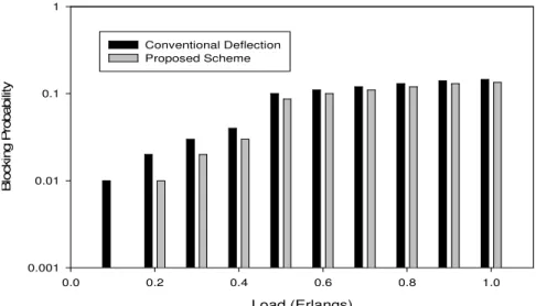
Fig. 3 shows the variation of the burst blocking probability with the traffic load between 0.1 and 1.The results show clearly that the proposed scheme reduces effectively blocking probability for low and fairly loaded network. Indeed, when load is 0.1 the relative improvement (i.e., [(blocking probability of conventional deflection routing)-(blocking probability of the proposed scheme)]/ (blocking probability of conventional deflection routing)) of the proposed scheme over conventional deflection routing scheme is about 90%. When load is 0.4 this improvement is 35 %. When load varies between 0.5 and 1, the variation of the burst blocking probability improves with the proposed scheme is between 10 % when load is 0.5 and less than 3 % when load is 1. The proposed scheme provides far better improvement in slightly loaded network than in loaded network. This can be explained as follows: when the offered load increases, the number of successful deflections tends to decrease, making the improvement brought by the proposed scheme less significant. Overall, the proposed scheme outperforms conventional deflection routing.
Load (Erlangs)
0.0 0.2 0.4 0.6 0.8 1.0
B
lo
c
k
in
g
P
ro
b
a
b
ili
ty
0.001 0.01 0.1 1
Conventional Deflection Proposed Scheme
Fig. 3: Blocking Probability comparison between proposed and conventional deflection routing
Core Node
Core Node
Outgress Edge Node Ingress
Brazilian Microwave and Optoelectronics Society-SBMO received 15 May 2010; revised 20 May 2010; accepted 5 Oct 2010 Brazilian Society of Electromagnetism-SBMag © 2010 SBMO/SBMag ISSN 1516-7399
Fig. 4 shows the variation of End-to-End (E2E) delay with the traffic load. As expected, the proposed approach incurs bigger delay as a response to the increase of burst losses when traffic load increases. In the worst case, the relative end-to-end delay increase with the proposed approach compared to deflection routing; this increase is still acceptable and comparable to that reported in [9].
Load (Erlangs)
0.0 0.2 0.4 0.6 0.8 1.0
M
e
a
n
E
2
E
D
e
la
y
(
m
ill
is
e
c
o
n
d
s
)
0.1 1
Coventional Deflection Proposed scheme
Fig. 4: End-to-end delay comparison between proposed and conventional deflection routing
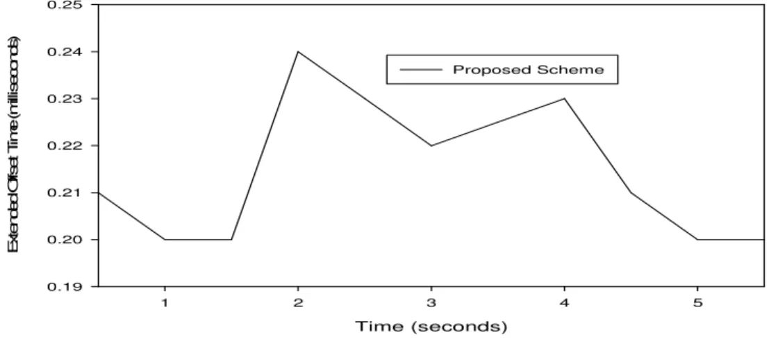
Fig. 5 shows the reaction (in terms of extended offset time) of the proposed scheme over time while varying the traffic load. The traffic load between time=0 and time=1 is equal to 0.1. At time=1, the traffic load has been increased to 1 for 2 seconds. At time=3, the traffic load is decreased to 0.1. It is also observed that the proposed scheme reacts rapidly to traffic load variations and it converges to a stable state within few time steps.
. Time (seconds)
1 2 3 4 5
E
x
te
n
d
e
d
O
ff
s
e
t
T
im
e
(
m
ill
is
e
c
o
n
d
s
)
0.19 0.20 0.21 0.22 0.23 0.24 0.25
Proposed Scheme
Fig. 5: The reaction of proposed scheme w.r.t variation in traffic load
Brazilian Microwave and Optoelectronics Society-SBMO received 15 May 2010; revised 20 May 2010; accepted 5 Oct 2010 Brazilian Society of Electromagnetism-SBMag © 2010 SBMO/SBMag ISSN 1516-7399
Probability of success (PS)
0.0 0.2 0.4 0.6 0.8 1.0
L
a
te
n
c
y
r
e
d
u
c
ti
o
n
(
%
)
0 10 20 30 40 50 60
conventional deflection Proposed scheme
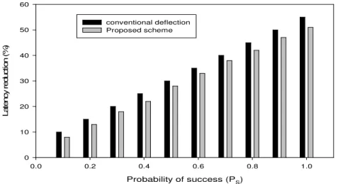
Fig. 6: Latency Improvement Vs Ps (probability of success during deflection)
Also, the results obtained in fig.7. shows that the proposed scheme can keep fairness-index almost unity and thus provides QoS.
Load (Erlangs)
0.0 0.2 0.4 0.6 0.8 1.0
F
a
ir
n
e
s
s
-i
n
d
e
x
0.0 0.2 0.4 0.6 0.8 1.0 1.2
Conventional deflection Proposed scheme
Fig. 7: Fairness-index Vs Load
VI.CONCLUSIONS
Brazilian Microwave and Optoelectronics Society-SBMO received 15 May 2010; revised 20 May 2010; accepted 5 Oct 2010 Brazilian Society of Electromagnetism-SBMag © 2010 SBMO/SBMag ISSN 1516-7399
REFERENCES
[1] C. Qiao, M. Yoo, “Optical burst switching (OBS)—A new paradigm for an optical Internet,” J. of High Speed Networks, vol. 8, pp. 69–84, 1999.
[2] C. Qiao, M. Yoo, “Choices, features and issues in optical burst switching,” Optical Network Magazine, vol.2, pp.36-44, 2000. [3]Amit Kumar Garg, R S Kaler, “Performance Analysis of an Integrated Scheme in Optical Burst Switched High-Speed Networks,” Chinese Optics Letters (Journal of OSA), vol.6, no.4, pp.244-247, 2008.
[4] Y. Chen, C. Qiao,“Performance Analysis of Optical Burst Switched Node with Deflection Routing,” Proceedings of IEEE ICC, vol. 2, pp.1355-1359, 2003.
[5] V. Vokkarane, S. Sitaraman, “Burst segmentation: An approach for reducing packet loss in optical burst switched networks,” Proceeding of IEEE ICC, vol.5, pp.2673-2677, 2002.
[6]A. Zalesky, “Evaluation of limited wavelength conversion and deflection routing as methods to reduce blocking probability in optical burst switched networks,” Proceeding of IEEE ICC, vol.3, pp.1543- 1547, 2003.
[7] T. Coutelen, A. Metnani,, “Measurement-based alternative routing strategies in optical burst-switched networks,” Proceedings of 7th International Conference on Transparent Optical Networks, vol.1, pp.224- 227, 2005.
[8] T. Coutelen, B Jaumard, “An efficient adaptive offset mechanism to reduce burst losses in OBS networks,” IEEE GLOBECOM , vol.4, no.5,2005.
[9] C. Hsu, T. Liu, N. Huang, “Performance analysis of deflection routing in optical burst-switched networks,” Proceedings of INFOCOM, vol.1, pp.66-73, 2002.
[10] A. Agusti, C. Cervello-Pastor, “A new contention less dynamic routing protocol for OBS using wavelength occupation knowledge,” Proceedings of the 12th IEEE Mediterranean Electro technical Conference, vol.2, pp.519- 522, 2004.
[11] T. C. K. Hui , C.K. Tham, “ Adaptive Provisioning of Differentiated Services Networks based on Reinforcement Learning,” IEEE Transactions on Systems, Man and Cybernetics, vol.4, pp.492- 501,2003.