Abstract— A simple and low-cost spectrum sliced microwave photonic filter with high tunability has been implemented. This is based on use of two Fabry-Pérot filters with same free spectral range connected in parallel but one filter with an external fiber delay. An extension of this configuration with Fiber Bragg Grating (FBG) as delay element is also demonstrated. This architecture overcomes the tuning difficulties of a single Fabry-Pérot filter employed as a slicing element. Flexible tunability, large overall free spectral range and high quality factor have been obtained with the proposed configuration owing to the use of fiber delay/FBG. Wide and step tuning has been achieved in the frequency range of 41.1GHz to 50.23GHz in steps of 2.28GHz. The additional components are another Fabry-Pérot filter and fiber delay/FBG which makes the proposed architecture highly compact and cost-effective. Most of the practical difficulties faced in use of optical fiber are eliminated using FBGs. The characteristics of proposed configuration with different applied delays using fiber and FBG were tabulated. An analysis of flexible tunable property of the filter was made in terms of length of fiber delay and grating length of FBG and the results were plotted. Also quality factor calculation of the proposed filter was discussed.
Index Terms— Fabry-Pérot (FP) filter, Fiber Bragg Grating, fiber delay, Free Spectral Range (FSR), Microwave photonics, Q-factor, spectrum slicing, tunability.
I. INTRODUCTION
Microwave photonics is today an innovative multidisciplinary and interdisciplinary field combining and transferring different technologies. Continued progress in photonic components and technology
sustains great interest in this field and expanding acceptance of photonics for microwave systems. The many advantages of microwave fiber-optic communication links over conventional coaxial or
waveguide links include reduced size, less weight, low cost and constant attenuation over the entire modulation frequency range. They have excellent reconfigurability, extremely wide bandwidth, low dispersion, high immunity to ElectroMagnetic Interference (EMI) and high information transfer
Flexible Tunable Spectrum Sliced Microwave
Photonic Filter Using Parallel Fabry-Pérot
Filters and Fiber Bragg Grating
R.K. Jeyachitra1, Dr. (Mrs.) R. Sukanesh2
1. Assistant Professor, Department of Electronics and Communication Engineering, National Institute of Technology (NIT), Thuvakudi, Tiruchirappalli, TamilNadu, India. Phone: +91 0431 2503320(Off.), +91
09443145540 (Mob), +91 04312459447(Res), Fax:
0431-2500133.Email:[email protected],[email protected],[email protected].
capacity. They are suitable for a number of applications such as personal communication networks, millimeter (mm)-wave radio LANs, antenna remoting, broadband video distribution networks and signal distribution for phased array antennas. With these new applications there are increasing
requirements for high performance devices for microwave and mm-wave systems where they are used due to broadband low-loss and high-speed transmission capability of optical fibers. There is a great
scope for developing 40GHz broadband cellular network technologies in the near term and there is an increased interest in the possibilities of using the 60GHz and 70GHz bands, with their excellent
frequency reuse, for broadband pico-cellular operations. The breakthrough in the design and demonstration of several ultra broadband photonic components has paved the way for wideband and
highly efficient optoelectronic converters used as important building blocks for microwave–optical links [1]. However, there is the difficulty of attaining the reconfigured band pass transfer function of
any filter with the traditional microstrip or waveguide Radio Frequency (RF) technologies. This difficulty can be overcome by external on-line measures in spectrum sliced microwave photonic filters.
Several techniques have been deployed for spectrum slicing in microwave photonic filters [2]
since 1996 up to 2008 and highly integrated and user-friendly software applications have also been developed [3] that enable the Computer-Aided Design (CAD) and simulation of these techniques. The fiber optic microwave and mm-wave filter demonstrated in the year 1996 is the first filter with highest
number of filter taps, greater sidelobe suppression and fine, clear spectral slices [4].A transmissive type FP filter with low spectral period was used to realize sub nanometer resolved optical sampling
with the reported FSR of 4.6GHz.
Since an FP filter is a fixed optical filter, there are serious limitations of tunability and weight
adjustment. The flexibility of this photonic microwave filter is very low and needs specially designed FP filter. It is difficult to achieve wide range of filter tunability since this requires the change of the
slicing filter FSR. To tune the filter response, the Fabry-Pérot cavity has to be greatly changed to modify the FSR and the cavity has to be finely adjusted using optical switches and piezoelectrics [6].
This severely limits the practical feasibility of the architecture.
We propose an extension to the approach used in [4], [5] in order to obtain enhanced and wide-range tunability. This proposed architecture uses two FP filters in parallel but one of them with an
adjustable fiber delay or FBG which gives flexible tunability in the range of 40GHz to 50GHz. Bragg gratings are attractive as sampling elements because the tap weights can be controlled via the grating
reflectivity, the sampling time can be controlled via the grating spacing, and the interaction wavelength can be controlled via the grating pitch [7]. Second section explains the topology of the
II. FILTER TOPOLOGY AND OPERATION
The general layout of the filter is shown in Fig. 1. The optical source is a low-cost, broadband Amplified Spontaneous Emission (ASE) spectrum which is obtained from a pumped Erbium Doped Fiber Amplifier (EDFA). The ASE signal level however is usually very small and requires further
amplification in order to overcome the losses introduced by the remaining components of the filter. The optical power from the source is split and spectrally sliced by use of two multiwavelength FP
filters connected in parallel, one with an adjustable delay implemented using either optical fiber or FBG, to obtain the equivalent set of spectrally equispaced optical sources. The output light from the
parallel combination FP filters is combined and subsequently modulated by RF signal by means of an external modulator and fed to an optical dispersive element providing a linear group delay
characteristic. The output signal from the dispersive element is fed to a photodetector and subsequent RF circuit.
Fig.1. General Layout of the proposed configuration.
III. THEORY
When Single-Sideband (SSB) modulation is employed for the RF signal and a single FP filter is used, the RF transfer function of the filter [5] is given as
R F k
N
– j [
(k – 1 )
τ
H (
) = R
P e
k = 1
∑
(1)
where Pk represents the output power from the k th
slice of the broadband source, R is the receiver responsivity, Ω is the RF frequency, and ∆τ represents the incremental differential delay experienced
by two adjacent spectral slices of the broadband source is given by
τ
=D L
λ
(2) where D (ps/km.nm) is dispersion parameter, L (m) is the length of fiber and ∆λ (nm) is wavelengthWhen two FP filters are used in parallel, the overall transfer function is given as
overall 1 2
H
( ) = H ( )+H ( )
(3)
1 2
k k
N N
– j [ (k–1) ( τ)] – j [ (k–1) ( τ+τ)]
k=1 k=1
=R
∑
P e
+
∑
P e
(4)
where τ represents the time delay offered by the fiber or FBG.
When FBG is used as a delay element [8],
r g g t g
T = D L
λ
= 2 n L / C
(5)where Tr is the round–trip time for a grating of length Lg, λt is the total shift in bragg wavelength, Dg
is the dispersion parameter, n is the average refractive index and c is velocity of light in the fiber.
IV.
NUMERICAL RESULTS AND DISCUSSIONThe MATLAB simulation platform was used to demonstrate the operation of the proposed microwave photonic filter shown in Fig. 2. To obtain sharply apodised sliced spectrum with N = 34 taps, only a 9nm portion (centered at 1531.8nm, the wavelength corresponding to the ASE maximum
of EDFA1) of the ASE output from EDFA1, was divided by means of a 1x2 splitter and fed to the FP filters connected in parallel. The output optical spectrum of broadband optical source was obtained
using OPTSIM toolkit. The output from the FP filters was added using a 2x1 optical coupler. The optical dispersive element was implemented by means of a coil of 46km of singlemode standard
optical fiber with dispersion parameter D = 17ps/km.nm and wavelength spacing of 0.28nm, although a linearly chirped fiber grating could also be employed. The output signal is amplified by EDFA2 and
fed to a photodetector.
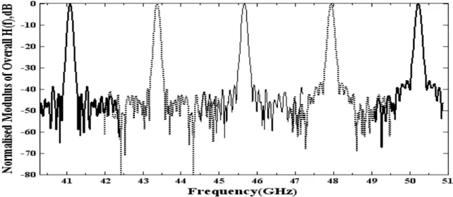
Fig. 3. Frequency characteristics of proposed configuration with the FP filter having same FSR with delay of 20, 42, 66, 92 and 122ps.
When two FP filters of same incremental differential delay τ1 and τ2 of 219ps were used in the
configuration but without fiber delay, the response of the filter was not different from the response of a single filter as obtained in [4].Then the two FP filters of same incremental differential delays τ1
and τ2 of 438ps (=17ps/km.nm x 92km x 0.28nm) were used in the proposed configuration along
with fiber delay. The fiber delay times τ = 122ps, 92ps, 66ps, 42ps and 20ps were offered by using
singlemode standard fiber and adjusting its length to 25.6km, 19.3km, 13.9km, 8.8km and 4.2km respectively. This configuration provides high FSR and flexible tuning range from 40GHz to 50GHz.
The FSR of this filter could be varied from 41.1GHz to 50.23GHz in steps of 2.28GHz. The filter frequency responses are shown in Fig. 3 obtained using (4) with the response of each configuration represented in a different trace, and other characteristics of this filter are mentioned in Table. I.
The delay times τ = 122ps, 92ps, 66ps, 42ps and 20ps were then offered by using FBG taking
average refractive index n = 1.447 and c = 299792458 m/s. Using (5) the grating length Lg was
adjusted to 12.613mm, 9.559 mm, 6.811 mm, 4.324 mm and 2.064 mm and the results are given in
Table. I. The same results as shown in Fig. 3. were obtained and are tabulated in Table. I. The required lengths of fiber delay were compared with required grating length. Thus FBGs of these
grating lengths form effective substitutes for optical fiber as delay elements. There is no need to manually change the fiber length to obtain flexible tunability as in case of FBG is used as delay
element. Also, the grating length required of FBG is very small in the order of millimeters compared to the length of fiber.
When no delay is given by fiber, the overall FSR is the frequency where a multiple of FSR of one filter is “sufficiently equal” to a multiple of FSR of the second filter. It is the first resonant frequency where the output powers of the filters sum up to give a total power of -3dB or more. Very
use of EDFA2.From Table I. the required grating length is very small and is in the order of
millimeter to obtain high FSR with step tunability.
TABLE I.COMPARISON TABLE OF CHARACTERISTICS OF
PROPOSED CONFIGURATION WITH DIFFERENT APPLIED DELAYS USING FIBER AND FBG
A. Q-Factor Calculation
The Q-factor of the overall filter is given as [9]
Q-factor = (Overall FSR) / (3dB bandwidth) (6)
Fig.4 shows the offset response of the filter at 50.23GHz for the final tunable resonant peak. The overall FSR of 50.23GHz and a 3dB bandwidth of 90MHz (f1~f2 =50.18 ~50.27GHz =90MHz) were
measured from Fig. 4. Using (6) the Q-factor of the filter at 50.23GHz was calculated and it is
approximately of 558.In similar way, the Q-factor of the other resonant peaks were measured individually.
Fig. 4. Offset response of the filter at 50.23GHz. S.No. Fiber Delay τ (ps) Required Length Overall
FSR (GHz)
3dB BW (MHz)
Quality Factor Fiber delay
(km)
Grating Lg
(mm)
F
Fig.5 gives FSR as a function by adjusting length of fiber dela
from 41.1GHz to 50.23GHz in grating length. The same results
length. The delay times τ = 122
grating length Lg of 12.613mm, 9
the practical difficulties faced i proposed architecture highly com
We achieved flexible tunabil employing two FP filters of same
Fig. 5. FSR as a function of length of Fiber delay.
n of length of fiber delay. The step tunability of th lay from 25.6km, 19.3km, 13.9km, 8.8km and 4.2
in steps of 2.28GHz respectively. Fig. 6 gives F lts as shown in Fig.3. were obtained using FBG w
22ps, 92ps, 66ps, 42ps and 20ps were offered by , 9.559 mm, 6.811 mm, 4.324 mm and 2.064 mm r
in use of optical fiber are eliminated using FB ompact and cost-effective.
Fig. 6. FSR as a function of Grating length.
V. CONCLUSION
bility for applications in the frequency range o me FSR of 2.28GHz (corresponding to differential
the filter was achieved 4.2km to vary the FSR
FSR as a function of with reduced grating
y using FBG with the respectively. Most of
BGs. This makes the
438ps) in parallel configuration, This flexible tunability has been varied as τ = 122, 92, 66, 42 and
2.28GHz. The results obtained ar there is no need to manually ch
length required of FBG is very sm the filter was analyzed in terms o
plotted. The Q-factor of the prop effective.
The authors gratefully acknow Prof. Arokiaswami Alphones of
[1] Chi H. Lee, editor, Microwave Pho
[2] R. Sukanesh, R.K.Jeyachitra, P. G spectrum slicing for microwave
(ICCCN) 2008, pp. 1-6, Dec.2008. [3] R. Sukanesh, R.K.Jeyachitra, Sha
photonic filters,” Proc. Int. Conf. M World Scientific Press.
[4] J. Capmany, D. Pastor, B. Ortega, very high sidelobe suppression usi 496, Mar.1999.
[5] R.K.Jeyachitra, R.Sukanesh and Sh Parallel Fabry-Pérot Filters and Fib 483, Dec.2009.
[6] Borja Vidal, Miguel A. Piqueras, parallel Fabry-Pérot filters.” Proc.I
[7] Kenneth O. Hill, Gerald Meltz, “F vol. 15, no. 8, pp.1263-1276, Aug. [8] Govind P. Agarwal, Author, Applic
[9] Lina ZHOU, Xinliang ZHANG, En
Optoelectron. China.vol. 2, no. 3, pp
R. K. Jeyachitra re Microwave and Opt respectively. She is c as lecturer and from working as Assistant research interests are microwave/ millim (PCF). She is a life member of IE, IETE
Dr. (Mrs.) R. Suk
B.E. (ECE) from G degree (Communic Medical Engineerin a faculty in the dep
n, with one of them connected to variable optical n achieved by the use of the external delay element nd 20ps to vary FSR discretely from 41.1GHz to 5
are same for either optical fiber or FBG as delay el change the fiber length to obtain flexible tunabili
small compared to the length of fiber. The flexible s of length of fiber delay and grating length of FBG
roposed filter was measured. This makes the system
ACKNOWLEDGMENT
owledge the wonderful suggestions and greatly of Nanyang Technological University (NTU), Si
REFERENCES
hotonics, CRC Press, Taylor & Francis Group, 2007,pg 26. Gautham, A. Raja and Shailesh Ajmera, “Investigation of th
e photonic filters,” in IEEE Proc. Int. Conf. Computation
hailesh Ajmera, K.Avinash, S.Manochandar, “Optical CA
f. Mech. and Elect. Eng. (ICMEE)2009, pp 93-98, Jul. 2009 a, “Fiber optic microwave and millimeter-wave filter with h sing sub nanometer optical spectrum slicing,” Electron. Lett
Shailesh Ajmera,” Flexible Tunable Spectrum Sliced Microwa Fiber Delay”, Proc. of IEEE-Asia Pacific Microwave Confere
s, Juan L. Corral, Javier Martí, “Tunable photonic microw
Int. Topical Meeting on Microwave Photonics, Oct. 2005, pp “Fiber Bragg Grating Technology Fundamentals and Overvie
1997.
lications of Nonlinear Fiber Optics, Academic Press, Elsevier Enuming XU, “Q value analysis of microwave photonic filters
pp. 269-278, February 2009.
received her B.E. degree in Electronics and Communicati ptical Engineering from Madurai Kamaraj University, Ma s currently pursuing research in microwave photonics. From 1 m 2004-2007 as assistant professor at J.J. College of Enginee nt Professor in the department of ECE, National Institute of T limeter-wave photonics, Radio-over-Fiber (ROF) systems and
E, ISTE and Member in OSA and SPIE.
ukanesh, senior professor in Biomedical Engineering receive Government College of Technology, Coimbatore in 1982.
ication Systems) from P.S.G. Technology, Coimbatore in ring from Madurai Kamaraj University, Madurai in 1999. Sinc epartment of ECE at Thiagarajar College of Engineering, Mad
al fiber delay or FBG. ent. The delay could be 50.23GHz in steps of
element. Using FBGs, ility. Also, the grating
ble tunable property of G and the results were
tem compact and
cost-y useful directions bcost-y Singapore.
the techniques deployed in
ion, Commun. Networking
CAD tools for microwave 9 and indexed in eProc. in
high density sampling and
tt, vol. 35, no. 6, pp. 494-wave Photonic Filter Using
rence(APMC2009), pp481-owave filter based on two pp. 205-208.
view”, J. Lightw. Technol., ier, 2006, pg 289.
ers”, Front.
ation Engineering, M.E. in adurai in 1995 and 1997 1998 to 2004 she worked eering, Trichy. Now she is f Technology, Trichy. Her nd Photonic Crystal Fibers