Abstract — Design and analysis of a 35 GHz metal photonic band gap (PBG) resonant cavity operating in the TE041-like mode has
been presented. The dispersion characteristics of a 2D metal PBG structure comprising of triangular array of rods has been obtained using FDTD method. Global band gap regions have been obtained to be used for the PBG cavity design. A mode map has been also generated to examine the occurrence of the possible modes in the PBG cavity. Electromagnetic simulation of the designed PBG cavity has been performed to study the operating modes and quality factors. Role of the number of metal rods layers around the defect in PBG structure has also been illustrated for confining the desired mode and deciding the diffractive quality factor. PBG cavity results have been compared with the analogous cylindrical cavity for the designed mode along with the possible nearby modes to examine the mode competition. It has been found that the mode competition has been successfully reduced in designed PBG cavity and nearly a single mode operation is achieved. It is hoped that present study would be useful for the application of the metal PBG structures in the Gyrotron devices to alleviate the mode competition problem while operating in the higher order modes.
Index Terms—FDTD, Gyrotron, PBG structure.
I. INTRODUCTION
Gyrotrons have emerged as the potential device for the generation of high power millimeter and
sub-millimeter waves with good efficiency among various devices of its class. In the recent past,
significant improvements in performance of the gyrotrons are achieved for both pulse as well as CW
operation [1]. Gyrotrons find variety of technological, scientific and industrial applications, including
electron cyclotron resonance heating (ECRH), electron cyclotron current drives (ECCD), material
processing, stability control and diagnostics of magnetically confined plasmas for generation of
energy by controlled thermonuclear fusion, dynamic nuclear polarization enhanced nuclear magnetic
resonance (DNP/NMR) spectroscopy, etc. [1]-[3].
High frequency operations of gyrotrons have made it possible to use them for newer applications
but still many challenges remain in terms of achieving stable single mode operation of the overmoded
cavities. At such higher frequency operation, significant reduction in transverse dimension of the RF
interaction cavities lead to increase in heat load on the cavity walls, fabrication difficulties as well as
increased problem of the beam interception [4]. High magnetic field requirement for the fundamental
Design and Analysis of Metallic Photonic
Band Gap Cavity for a Gyrotron
Ashutosh and P. K. Jain
Center of Research in Microwave Tubes, Department of Electronics Engineering, Indian Institute of Technology (Banaras Hindu University) Varanasi-221005, India.
mode operation is another serious limitation. Use of the overmoded structures can surmount these
issues, but mode competition becomes a serious problem. The overmoded RF cavities,
conventionally, open ended tapered cylindrical resonators, can be replaced by the metallic photonic
band gap (PBG) structures to control the problem of mode competition. Additionally, the transverse
dimension of PBG cavity is larger than the conventional cavity for the same operating mode and
frequency [4]. For the moderate power level at sub-millimeter wavelengths, PBG cavities could be a
substitute to achieve a mode selective operation. Sirigiri et al. have successfully demonstrated
experimental implementation of a PBG interaction cavity in a 140 GHz gyrotron [4]. Other electron
beam devices, like, high gradient accelerator [5], multibeam reflex klystron [6], Cherenkov device
using slow-wave structure [7], and backward wave oscillator [8] have been also proposed/realized
incorporating the PBG structures for the merit of its mode selectivity.
In this paper, design and analysis of a 35 GHz metal PBG cavity operating in the higher order
TE041-like mode is presented. The objective of this paper is to demonstrate the mode selective
operation of the PBG cavities to be used in the gyrotron devices as its RF interaction structure while
operating at the higher order modes. Dispersion diagram, i.e., band structure is obtained using
Yee-cell based FDTD method in the TE mode of propagation for a two dimensional triangular PBG lattice,
realized from the metallic cylindrical rods in vacuum background. Global band gap diagram utility for
the design of PBG cavity is demonstrated. Eigenmode simulation of the PBG cavity is also presented
using a commercial 3D electromagnetic code, ‘CST Microwave Studio’. Scattering parameter of the
PBG cavity is also obtained to inquire the mode existence. Resonant frequencies obtained analytically
are compared with the simulated values for different ratio of rod radius to lattice constant. The
diffractive and ohmic quality factors of the PBG cavity are determined. Effect of structure layers
around the defect on quality factors is observed. Further, resonant frequency and qualityfactor of the
designed metal PBG cavity are compared with the analogous conventional cylindrical cavity
including other possible nearby modes.
II. PBG STRUCTURE MODEL
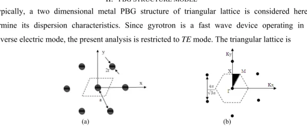
Typically, a two dimensional metal PBG structure of triangular lattice is considered here to
determine its dispersion characteristics. Since gyrotron is a fast wave device operating in the
transverse electric mode, the present analysis is restricted to TE mode. The triangular lattice is
(a) (b)
azimuthally symmetric structure and provide more global band gap regions compared to the
rectangular lattice. The lattice in configurational space and reciprocal space are shown in Fig. 1,
where shaded portion show the Brillouin zones. Calculation of eigenvalues along the sides (Γ-X, X-M
and M-Γ) of Brillouin zone provides whole frequency spectrum of the lattice with wave vectors, i.e.,
dispersion characteristics.
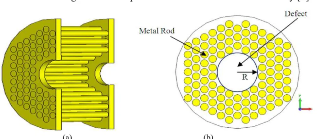
For designing a PBG cavity, the choice of rod radius and lattice constant must be proper so that the
desired mode at the specific frequency must lie in band gap and other nearby modes in pass band. For
the present cavity design, typically, 19 innermost rods are removed from the triangular lattice formed
by copper rods and 4 layers surrounding the defect are kept (Fig. 2). Two end plates have holes of
different radii. Smaller radius hole ensures prevention of the RF signal propagation toward input side
due to the higher cut-off frequency and bigger radius hole at the output end is used for conversion of
standing mode into the travelling mode to couple out the RF radiation from the cavity [4].
(a) (b)
Fig. 2. PBG cavity for gyrotron cavity made of triangular lattice of copper rod having defect (a) 3-D cut-view (b) front view at mid plane showing the cavity radius (R).
(a) (b)
Fig. 3. (a) Band structure of the 2-D metallic triangular lattice PBG structure for TE mode with r/a = 0.4 obtained from Yee- cell based FDTD method (shaded portions show global band gap regions) and, (b) its global band gap diagram.
III. FDTD ANALYSIS
A. Dispersion characteristics
Photonic band structure is calculated using Yee-cell based finite difference time domain (FDTD)
method and shown in Fig. 3(a). A modified unit cell is considered here as the computational domain
obtained for the r/a ratio of 0.4 and global band gap regions are shown by shaded portions.
Obviously, several band gap regions can be seen in the figure (Fig. 3(a)). Global band gaps are
examined for the entire range of r/a (from 0.01 to 0.5). These band gap regions are plotted as Fig.
3(b) and this plot is found identical with that obtained using MIT PBGSS code [10]. In Fig. 3(b),
several band gap regions are observed which could be used as the operating frequencies of the PBG
interaction cavities.
B. Mode spectrum
For the confined modes, defect radius of PBG interaction structure can be taken as similar to
cylindrical waveguide using the following well known relation [11]:
r n m
f cx R
π
2,
= (1)
where, c is velocity of light, fr is resonant frequency of interaction structure and xm,n is eigenvalue,
which is root of TE mode dispersion relation J’n(x). Here, J’n(x) is the derivative of nth order Bessel
function of argument x. Since, gyrotron oscillator operates close to cutoff frequency; this
approximation acquired from the cylindrical waveguide cut-off frequency equation is valid. Equation
(1) can be rewritten in terms of normalized frequency fn ( = a fr /c) as:
n n m
f ax R
π
2 ,
= . (2)
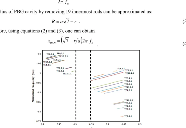
The radius of PBG cavity by removing 19 innermost rods can be approximated as:
r a
R≈ 7− . (3)
Therefore, using equations (2) and (3), one can obtain
xm,n=
(
7−r a)
2π fn . (4)Fig. 4. Mode spectrum in the global band gap of a triangular lattice metal PBG cavity (formed by removing 19 rods).
Now, from equation (4), normalized frequency can be obtained for a particular r/a ratio and
eigenvalue of the desired mode. Thus calculated normalized frequency is further examined whether it
cavity by varying r/a ratio. For the case, in which 19 rods have been removed, the mode map is
generated and shown as Fig. 4. From this map, one can easily locate the design point for the particular
operating mode and resonant frequency. Region between dotted lines demonstrate a void in the mode
existence. Obviously, at r/a = 0.35, PBG cavity operates with minimum mode competition in the
TE041-like mode. It is important to note that mere information of global band gap region does not
provide the mode existence. Sometimes, the local band gaps are enough to confine a mode; hence, the
existence of modes must be thoroughly investigated.
C. PBG cavity design
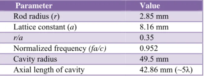
From Fig. 4, value of r/a = 0.35 with the normalized frequency 0.952 can be taken near the edge of
band gap. The cavity design parameters are listed in Table I below:
TABLE I.DESIGN PARAMETERS OF A 35GHZ PBG CAVITY
Parameter Value
Rod radius (r) 2.85 mm
Lattice constant (a) 8.16 mm
r/a 0.35
Normalized frequency (fa/c) 0.952
Cavity radius 49.5 mm
Axial length of cavity 42.86 mm (~5λ)
IV. RESULTS AND DISCUSSION
The designed PBG cavity is simulated for its electromagnetic behavior using a commercial
simulation code “CST Microwave Studio”.
A. Field distribution
Simulation is carried out for the frequency range of 33-38 GHz using eigenmode solver to examine
the existence of possible confined modes. All metal boundaries are considered with the tangential
component of electric field zero (Et= 0). A well confined TE041-like mode is observed in the cavity at
frequency 34.94 GHz (Fig. 5). In the simulation, few nearby modes are also observed in the cavity but
their quality factor is much lower than that of TE041 mode. Additionally, these modes are widely
separated from the TE041 mode. The ohmic qualityfactor for the TE041 mode is found as 27150.
B. Resonant frequency
The normalized resonant frequency (fn) is calculated analytically by varying r/a ratio for the TE041
-like mode (equation (4)). Through EM simulation, the resonant frequencies of the PBG cavity are
estimated for the different r/a ratio. Both analytical and simulation results are compared and found to
be within 3% variation (Fig. 6). Further, it can be seen in Fig. 5 that the EM fields near metal posts
are not perfectly confined in the defect and slightly penetrate into the rods region; hence, the cavity
radius considered analytically is smaller than the effective radius. Consequently, simulated resonant
frequencies are lower than the analytical values. The band gap width at the design point is 0.0286
(normalized). In the conventional cylindrical cavity, presence of all modes is inevitable, while in the
PBG cavity, only that modes will be confined in defect which resonant frequency lie in the global
band gap width. Consequently, PBG cavity provides a mode selectivity.
Fig. 6. Variation of resonant frequency with ratio of rod radius (r) to lattice constant (a) for TE041-likemode.
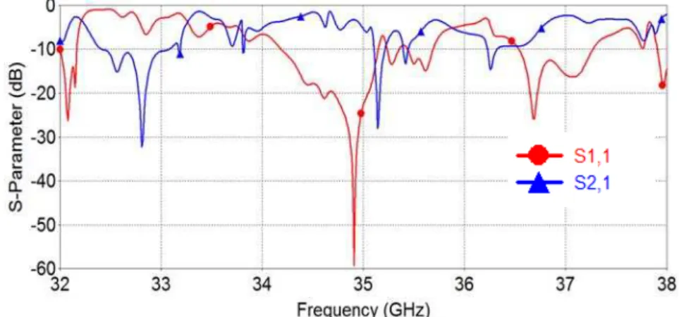
Fig. 7. Scattering parameter of the metallic PBG cavity obtained through CST Microwave Studio.
C. Scattering parameter
In order to examine the reflection and transmission behavior of this metal PBG cavity, structure is
also simulated using transient solver of ‘CST Microwave Studio’ (Fig. 7). It can be observed from the
figure 7 that only at 34.94 GHz, reflection coefficient (S11) is very low and transmission coefficient
(S21) is maximum. This reveals the existence of a propagating mode at this frequency in the PBG
cavity with no mode competition. Obviously, existence of some other modes is apparent widely apart
around 20 MHz. This small bandwidth provides a mode selectivity as well as higher quality factor in
comparison to the cylindrical cavity.
D. Quality factor
In order to estimate the different structure losses in terms of the cavity quality factor (Q),
simulations were performed for both diffractive as well as ohmic quality factors using the relevant
boundary conditions. The associated structure losses are Qohmic and Qdiffractive, which accounts for losses
due to finite conductivity of the metal surface and EM field leakage through the PBG cavity structure,
respectively. The overall quality factor can be obtained using well know relation,
(
ohmic)
(
diffractive)
total
Q
Q
Q
1
1
/
1
=
+
.Quality factor (Q) of metal PBG cavity is determined using transient solver tool of CST Microwave
Studio. For Qdiffractiveestimation,entire cavity volume with input and output beam holes (shown in Fig.
2) is excited by a discrete current port at its centre for the excitation frequency range 30 - 40 GHz.
Field probe is positioned inside the cavity to record electric field spectrum at the maximum value
which yields the diffractive quality factor using the full width half maximum. The energy decays very
slowly which demonstrate the resonant behavior of the interaction structure (Fig. 8(a)). The field
maximum is observed at the desired of 34.94 GHz. The diffractive quality factor value, with 4 layers
of rods around the PBG defect forming the cavity, is obtained as 1750 (Fig. 8(b)). For the estimation
of ohmic quality factor Qohmic of PBG cavity, eigenmode solver of CST Microwave Studio is used
with all metal boundaries. For calculating the ohmic quality factor, the copper material has been
considered (electrical conductivity = 5.8x10⁷ S/m, permeability = 1, density = 8930 kg/m3, thermal
conductivity = 401 W/K/m). Surface roughness has been assumed to be zero, i.e., smooth surface has
been considered. Temperature variation of rods has not been taken care of in simulation while
boundary temperature has been kept isothermal. No cooling of the rods has been involved.
(a) (b)
Fig. 8. (a) Energy decay of the field (b) frequency spectrum of probed electric field.
E. Effect of number of PBG structure layers on the cavity loss and quality factor
Diffraction of EM fields from the layers of rods decreases with the increase in number of layers
around the cavity. Moreover, this reduction of the field outside PBG cavity results in better
confinement of EM fields inside the PBG cavity thereby enhancing the diffractive quality factor of the
keeping the other structure parameters constant. Fig. 9 demonstrates the field pattern in the PBG
cavity at 34.94 GHz frequency. Variation of quality factors with the number of layers of the metal
rods is shown in Fig. 10. Sufficient number of rod layers is required to reduce diffraction losses due to
EM wave leakage from the gaps between the metal rods. On the other hand, ohmic quality factor of
the PBG cavity decreases with the increase in the number of metal rod layers around the defect. This
happens because of increase in ohmic losses involved due to increase in the imperfect metal
boundaries in the form of rods of the PBG structure. Ultimately, total quality factor of the PBG cavity
enhances with the increase in number of rod layers around the defect. So, for well confinement of the
desired mode within the defect, sufficient number of rod layers are required which also leads to high
cavity quality factor.
(a) (b) (c)
Fig. 9. Electric field distribution inside the PBG cavity with (a) two, (b) three, and (c) four number of layers around defect.
Fig. 10. Variation of quality factor with number of metal rod layers around defects.
F. Comparison with cylindrical cavity
The RF performance of the metal PBG cavity is also compared with the conventional cylindrical
cavity to realize the qualitative strength of designed mode along with the nearby modes. The resonant
frequencies and ohmic quality factors of the nearby modes of the designed TE041 mode are shown in
Table II (TE041 mode is shown in bold). Obviously, Q-factor of TE041 mode is comparable to that of
the other hand, Q-factor of the TE041-like mode for PBG cavity is very high in comparison to that of
nearby modes. Particularly, TE241 mode is the strongest competing modes to TE041 mode. Quality
factor of TE241 mode in cylindrical cavity is 49333, which is comparable to that of TE041 mode. Hence
possibility of getting excitation of TE241 mode is equally probable. On the other hand, in the PBG
cavity case, quality factor of TE241 mode is very low comparable to TE041 mode hence coupling will be
weaker and the possibility of excitation of TE241 mode is reduced. This reveals dominance of TE041
mode and is most likely to resonate in structure. Other modes having very low Q-factor as well as less
azimuthal symmetry are less likely to involve in the interaction with electron beam. Thus, the
possibility of mode switching can be avoided using the mode selective property of PBG cavity. In the
cylindrical cavity gyrotrons, mode jumping into unwanted modes is inevitable but once device
oscillates in a particular mode, it would not switch to other mode and moreover, power grows only in
the sustained oscillating mode. The presence of TE241 competing mode reduces the efficiency of the
device in cylindrical cavity case while in the PBG cavity, this mode is eliminated.
TABLE II.FREQUENCY AND OHMIC Q-FACTOR FOR VARIOUS MODES IN CYLINDRICAL AND PBG CAVITIES
Resonant Mode Cylindrical Cavity PBG Cavity
Frequency (GHz)
Ohmic Quality factor
Frequency (GHz)
Ohmic Quality factor
TE4,3,1 33.16 32440 33.07 8365
TE11,1,1 33.60 11250 33.58 7715
TE7,2,1 33.68 37109 33.65 9816
TE2,4,1 34.56 49333 34.55 12766
TE0,4,1 34.98 50886 34.97 26261
TE12,1,1 35.11 10225 35.02 7982
TE5,3,1 36.63 46659 36.57 8397
TE8,2,1 36.84 37925 36.83 7770
TE3,4,1 38.27 50781 38.25 9856
V. CONCLUSION
In the view of role of PBG structures in preventing mode competition in gyrotrons, mode selective
metal PBG cavity structure has been investigated for its electromagnetic behavior. The dispersion
characteristic of a metal PBG structure has been obtained using the FDTD method which is less
cumbersome and easy to implement. Using the dispersion characteristics, a global band gap diagram
of metal PBG structure in TE mode has been obtained. Use of this diagram in designing a photonic
crystal device operating in desired mode and frequency is also described. The operating frequency of
the PBG cavities can be scaled to any other frequency and mode with the proper selection of lattice
constant and defect size.
To validate the analysis and design of the metallic PBG cavity, EM simulation is also performed
using commercial simulation code ‘CST Microwave Studio’. Simulation result confirms a well
confined TE041-like mode at 35 GHz resonant frequency in the designed metal PBG cavity. In this
cavity, no other competing mode with appreciable Q-factor is found. The analytical resonant
frequency agrees with the simulated value ~ 3%. Scattering parameter curve also supports the
layers around the defect in the PBG structure, diffractive quality factor increases and consequently the
field confinement is better. Simultaneously, the ohmic quality factor decreases due to increased losses
involving rods. Diffraction of EM fields through the lattice of metal rods decreases with the increase
in the number of metal rod layers. Consequently, for the well confinement of a desired mode with
high Q in defect region; at least 3-4 layers of rods are necessary. Comparing the designed PBG cavity
with the analogous cylindrical cavity for the frequency and ohmic quality factor of the designed mode
and possible nearby modes, it has been found that PBG cavity do not encourage competing modes.
The present analysis and design study of the metal PBG cavity structure would be useful in
understanding the electromagnetic behavior of the metal PBG structure and its application as the RF
propagating structures for the active as well as passive devices in the microwave to sub-millimeter
wave frequency range.
ACKNOWLEDGMENT
One of the authors (Ashutosh) is thankful to Centre of Advanced Study (University Grant
Commission), Department of Electronics Engineering, IIT (BHU), Varanasi for the financial support.
REFERENCES
[1] Manfred Thumm, State-of-the-Art of High Power Gyro-Devices and Free Electron Masers, KIT Scientific Reports 7540, 2009.
[2] Y. Carmel, K. R. Chu, M. Read, A. K. Ganguly, D. Dialetes, R. Seeley, J. S. Levine, and V. L. Granatstein, “Realization of a stable and highly efficient gyrotron for controlled fusion research,” Physical Review Letters, vol. 50, no. 2, pp. 112–116, Jan. 1983.
[3] C. D. Joye, R. G. Griffin, M. K. Hornstein, Kan-Nian Hu, K. E. Kreischer, M. Rosay, M. A. Shapiro, J. R. Sirigiri, R. J. Temkin, P. P. Woskov, “ Operational Characteristics of a 14-W 140-GHz Gyrotron for Dynamic Nuclear Polarization,”
IEEE Trans Plasma Sci, vol. 34, no. 3, pp. 518–523, June 2006.
[4] J. R. Sirigiri, K. E. Kreischer, J. Macuhzak, I. Mastovsky, M. A. Shapiro, and R. J. Temkin, “Photonic-Band-Gap Resonator Gyrotron,” Physical Review Letters, vol. 86, no. 24, pp. 5628 – 5631, June 2001.
[5] E. I. Smirnova, A. S. Kesar, I. Mastovsky, M. A. Shapiro, and R. J. Temkin, “Demonstration of a 17-GHz, High-Gradient Accelerator with a Photonic-Band-Gap Structure,” Physical Review Letters, vol. 95, no. 7, pp. 074801, Aug. 2005.
[6] Kyu-Ha Jang, Seok-Gy Jeon, Jung-II Kim, Jong-Hyo Won, Jin-Kyu So, Seung-Ho Bak, Anurag Srivastava, Sun-Shin Jung, and Gun-Sik Parkb, “High order mode oscillation in a terahertz photonic-band-gap multibeam reflex klystron,”
Appllied Physics Letters, vol. 93, no. 21, pp. 211104, 2008.
[7] Xi Gao, Ziqiang Yang, Yong Xu, Limei Qi, Dazhi Li, Zongjun Shi, Feng Lan, and Zheng Liang, “Dispersion characteristics of a slow wave structure with metal photonic band gap cells,” Nuclear Instruments and Methods in Physics Research A, vol. 592, no. 3, pp. 292-296, July 2008.
[8] Han, Seong-T., Seok-Gy Jeon, Young-Min Shin, Kyu-Ha Jang, Jin-Kyu So, Jong-Hyun Kim, Suk-Sang Chang, Gun-Sik Park, “Experimental Investigations on Miniaturized High-Frequency Vacuum Electron Devices” IEEE Trans. Plasma Sci., Vol. 33, pp. 679, 2005.
[9] Ashutosh, and P. K. Jain, “FDTD Analysis of the Dispersion Characteristics of the Metal PBG Structures,” Progress In Electromagnetics Research B, vol. 39, pp. 71-88, 2012.
[10]E. I. Smirnova, C. Chen, M. A. Shapiro, J. R. Sirigiri, and R. J. Temkin, “Simulation of photonic band gaps in metal rod lattices for microwave applications,” Journal of Applied Physics, vol. 91, no. 3, pp. 960-968, Feb. 2002.