INTRODUCTION
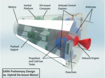
The SARA satellite was conceived as a microgravity recoverable and reusable research platform by both Brazilian Institute of Aeronautics and Space (IAE) and Space Agency (AEB). Figure 1a shows an artistic design of the platform and Fig. 1b, the planned launch vehicle of the spacecraft. The satellite was designed to carry a 55 kg payload mass, with total launch mass not exceeding 350 kg. Missions were projected to take place in circular orbits at 300 km altitude, with two-degree inclination. After completion of the microgravity experiments, up to ten days, the reentry procedure began by providing the right positioning of the satellite followed by the deboost impulse. Final deceleration took place by a high performance parachute system (Koldaev and Moraes, 1997). The spacecraft was scheduled to pass through a series of Tuali¿cation tests in ballistic Àights reaching 350 km apogee and falling at about
300 km from the launch site. The system should be accelerated by a Brazilian VS-40 sounding rocket (Fig. 1b).
To date, solid and liquid rocket propulsion systems were the only technological means considered for the deboost
An Optimized Hybrid Rocket Motor for the SARA Platform
Reentry System
Pedro Luiz Kaled Da Cás, Cristiano Queiroz Vilanova, Manuel Nascimento Dias Barcelos Jr.*, Carlos Alberto Gurgel Veras
Universidade de Brasília - Brasília/DF – Brazil
Abstract: This paper has described a system design process, based on a multidisciplinary optimization technique, of a conceptual optimized hybrid propellant rocket motor. The proposed engine could be a technological option for the reentry maneuvering system of the Brazilian recoverable satellite (SARA), which was designed by the Brazilian Institute of Aeronautics and Space. The resulting optimized propulsion system must be viewed as a proof of concept allowing comparison to more conventional technologies, i.e., liquid and solid motors. Design effort was conducted for hybrid SURSHOODQWVHQJLQHVEDVHGRQDOLTXHI\LQJIXHOVROLGSDUDI¿QDQGWZRGLIIHUHQWR[LGL]HUV+2O2KLJKWHVWSHUR[LGH and self-pressurizing N227KHPXOWLGLVFLSOLQDU\FRQ¿JXUDWLRQRSWLPL]DWLRQWHFKQLTXHZDVVXSSRUWHGRQJHRPHWULFDO operating parameters of the motor, rather than on performance, in order to facilitate subsequent design and fabrication. Results from the code presented a hybrid motor, which was considered a competitive alternative for the deboost engine when compared to the traditional chemical systems, solid and liquid bipropellant, and monopropellant. The estimated mass of the reentry system, for the cases addressed in this study, varied from 22 to 29 kg, which is lower than either liquid bipropellant or solid engines formerly proposed.
Keywords:+\EULGURFNHWSURSXOVLRQ0XOWLSK\VLFVDQDO\VLV'HVLJQRSWLPL]DWLRQ
Received: 18/04/12 Accepted: 21/06/12 *author for correspondence: [email protected]
Faculdade UnB-Gama- Área Especial 2, Lote 14, Setor Central Gama-DF/ CEP: 72405-610- Brazil
(a) (b)
motor (Villas Bôas et al., 2006). Hybrid propellant rocket engines, however, could be a competitive alternative for the reentry system in light of the recent reported technological advances, largely to those concerned with improvements in solid fuel regression rate.
The Universidade de Brasília hybrid propulsion team (HPT - UnB) has a considerable history in developing and testing hybrid rocket engines and small sounding rockets, in which the thrust and burning times (impulse) are quite similar to those claimed by the SARA deboost system (Viegas and Salemi, 2000; Santos, 2006; Contaifer, 2006). Hybrid rockets should be considered an attractive option for the Brazilian space program by virtue of their relative lower development cost, simple construction, and safe operation. This paper thus has described a system design process, based on a multidisciplinary optimization tech-nique, of a conceptual hybrid rocket motor for the reentry maneuver system of the Brazilian recoverable platform (SARA). The resulting optimized propulsion system should be viewed as a proof of concept, allowing direct compari-son to the well-known solid and liquid technologies, which were previously investigated by Villas Bôas et al. (2006). The optimization code based on a genetic algorithm, as presented in this work, should be considered a modern and essential design assistance tool for a broad utilization of hybrid propellant rocket engines.
HYBRID PROPELLANT ROCKET ENGINES
In spite of all claimed advantages of hybrid rocket engines over the solid and liquid counterparts, the related weaknesses should be analyzed in more details as to assure the technology would not be disregarded following a ¿rst assessment for the proposed application (debooster).
Recently, Karabeyoglu (2008) highlighted some nontech-nical challenges that hybrid rockets face in the present days: lack of technological maturity; competition against established solid and liquid technologies; propulsion industry ¿neness with the status quo; and smaller groups of rocket professionals regarding solid and liquid rockets.
We add to those nontechnical challenges some key tech-nological disadvantages of hybrid propulsion, compared to solid and liquid corresponding systems as pointed by Altman and Holzman (2007): low regression rate of the solid fuel surface; low bulk density; combustion ef¿ciency; 2/F shift; and slower transients.
In a more recent study, 2iknine (2006) analyzed whether the renewal interest of hybrid fuels could lead to a successful commercial venture in the near future. The author claimed that, for a commercial project, the risk of introducing a new low-cost technology should be justi¿ed only if the present costs pose relevant ¿nancial dif¿culties. The author also pointed that, when high-thrust level is required, a high fuel mass Àow should be delivered, which is, in particular, the primary challenge in hybrid motor operation. This challenge may thus explain the currently observed commercial failure of the hybrid propellant rocket technology.
Davydenko et al. (2007) listed key advantages of hybrid propulsion system over either solid, monopropellant or bipropellant propulsions, which, when brought to the desired application, would increase the chances of the anticipated propulsion system, based on:
safety (in manufacturing, transporting, and storing as a consequence of separate fuel and oxidizer);
reliability (due to the larger margin of tolerance in grain imperfections as well as ambient conditions);
Àexibility (by virtue of stop-restart capabilities and thrust modulation);
costs (due to low investments costs for development and operation as well as those costs associated with the materi-als to fabricate the motor, and general availability of the required materials and technologies);
environment (since combustion products are often nontoxic gases and propellants are not hazardous to storage and transport).
Compared to liquid rocket engines, Davydenko et al. (2007) added that the use of hybrid rocket technology, as suggested in this study, would increase system reliability on account of reduction in:
propulsion system development periods, from about four years to less than ten months;
fabrication cost, by a factor of about two, owing to the application of thermal protective carbon-containing composite materials;
operating costs, by 40 to 50;
cost of ¿re-and-explosion safety systems.
disregard hybrid rocket for the deboost system. Brazil still lacks an established rocket propulsion industry; therefore, introducing a new low-cost technology brings no risk, in contrast, it should be encouraged. The thrust level and burning times of the deboost system do not require high fuel mass Àow rate, which may be possible with a single port con¿guration design, further simplifying the propulsive system. As for the nontechnical challenges, after the paper written by Karabeyoglu (2008), we also believe they are not impeditive to place hybrid propulsion as an essential option for near future consideration of the Brazilian space market. The points raised in Davydenko et al. (2007) are also very promising to disregard the hybrid system technology as proposed in this study.
MULTIDISCIPLINARY DESIGN OPTIMIZATION CODING
Genetic algorithm (GA) may be de¿ned as a stochastic search and optimization method with embedded character-istics closely following the biological evolution observed in nature. By such means, the method chose the ¿ttest individuals from generation to generation approaching, successively, a better solution for the problem. GA has been employed, more intensively, in aerospace systems designed after the 1980s (Anderson, 2002). Anderson (2002) has highlighted that the method can be applied to solve aerospace problems in particular ¿elds, such as: guidance, navigation and control; aerodynamics; multidisciplinary design; propulsion; structures; scheduling and control; Àight test data extraction, among others. GA can be applied in the conceptual phase of design as a substitute to more traditional trial and error methods. As pointed by Akhtar and Lin-sh (2007), GA, compared to gradient-based methods, allows optimization-like tools to support the conceptual phase of design by combining discrete, integer, and continuous vari-ables with no requirement for an initial design. The method has also the ability to address nonconvex, multimodal, and discontinuous functions of a given problem (Akhtar and Lin-sh, 2007). More recently, optimization analysis of hybrid rocket engines has been applied to launch vehicles (Rhee et al., 2008; DaLin et al., 2012).
An optimization problem can be expressed as the mini-mization of an objective function under certain equality and inequality constraints. The formulation of a generic optimiza-tion problem is de¿ned as Eqs. 1 to 4:
,
minS!Sz s q s^ ^ hh (1)
, ,
h s q s^ ^ hh=0h!Rhh
(2)
, ,
g s q s^ ^ hh< 0g!Rhg
(3) |
S s R SL S SU
S
! # #
=" h ,
(4)
where,
z is the objective function, s is the set of design variables, q is the set of design criteria, and
h and g are respectively equality and inequality constraints.
The design variables and constraints belong to a set of real numbers, whose dimensions are represented by ns, nh and ng, respectively. The values of the design variables are limited by lower and upper bounds ([SL,SU@), de¿ning the so-called box constraints.
The objective function and the constraints are built as functions of design criteria and design variables. In a multi-disciplinary design optimization setup, the design variables are de¿ned by parameters that represent different physical aspects. For instance, in hybrid propulsion systems, param-eters, such as geometry or shape, dimensions and pressure of the combustion chamber and the mass Àow rate of oxidant, may be taken as design variables.
In a multidisciplinary optimization framework, the design criteria are associated with quantities that describe system performance and behavior. As regarded to hybrid propulsion systems, quantities such as trust, burning time, variation of velocity and mass may be considered as design criteria. In general, for a multidisciplinary optimization problem, the design criteria are dependent on the response of the multidisciplinary system, which can also be a function of the design variables.
PROBLEM STATEMENT AND METHODS
A candidate hybrid rocket engine to perform the reentry mission would be composed, basically, of a convergent-diver-gent nozzle, a combustion chamber, a liquid oxidizer tank, and a gas pressurization subsystem. The latter would be disre-garded, depending on the choice of the oxidizer. For instance, the self-pressurizing characteristics of nitrous oxide would circumvent the use of such subsystem.
engine relies on a self-pressurizing N22 and paraf¿n-based solid fuel (Almeida and Santos, 2005). A pressurizing subsystem is therefore not necessary, simplifying the ¿nal design complexity and cost for the reentry motor. The SARA spacecraft was also conceived to have an attitude control system. If nitrous oxide is the preferred oxidizer, the system could be based both on cold gas or thermo catalytic decomposition of N22, unifying all the spacecraft propulsive requirements accordingly (Campbell et al., 2008).
The second proposition is more conventional, as it is based on hydrogen peroxide and on a pressurization subsystem. In both cases, paraf¿n was considered as the solid fuel. An injec-tor plate based on pressure swirl atomizers was chosen for oxidizer injection into the combustion chamber. This system would signi¿cantly increase the solid fuel regression rate as compared to a showerhead injector type. The hybrid motor would be made of a cylindrical container with spherical ends. The nozzle would be of conic shape, made of aluminum with carbon phenolic insert for thermal protection. The combustion
chamber should also be made of aluminum with added ther-mal insulation for the postcombustion chamber.
The main reentry mission aspects were presented and discussed by Villas Bôas et al. (2000), namely: deboost impulse should produce a velocity reduction of the order of 235 to 250 m/s; and total burning time of the motor should be between 50 and 200 seconds.
These performance characteristics, though, are not stand-alone. The propulsive system should also be subjected to geometric constraints, as well as total mass limitation, on account of the launch vehicle operational envelope and overall mission ef¿ciency. Following that, Villas Bôas et al. (2000) proposed three different con¿gurations for the engine (debooster): liquid bipropellant (LBP), liquid monopropellant (LMP), and solid propellant (SP). The LBP alternative was composed of a liquid rocket engine system based on unsymmetrical dimethylhydrazine (UDMH) and nitrogen tetroxide (NT2), with engine chamber feeding provided by means of an inert gas (nitrogen) pressur-ization subsystem. The second option (LMP) was a hydrazine monopropellant system. As for the LBP, engine chamber feeding should also be provided by an inert gas (nitrogen) pressurization subsystem. The last con¿guration (SP) should be based on the technology developed at the IAE for the Roll Control System (PCR/S-IV) of the sounding rocket Sonda-IV. Engine thrust would come from the solid propellant end-burn grain type. The propellant grain was conceived as a variable burning area; ¿nal thrust was about ¿ve to six times lower than the initial thrust.
Figure 2 shows a conceptual design of the spacecraft and its main components. As it can be seen, the engine for deboosting must meet some dimensional requirements. The study conduct-ed by Villas Bôas et al. (2000) showed propulsion system mass varying from 35.1 to 47.3 kg. Size and volume of the systems were not presented, however engine system and subsystem were assumed to ¿t the engine bay of the SARA platform.
As pointed by Kwon et al. (2003), in designing a hybrid motor the grain con¿guration, combustion ef¿ciency, oxidizer tank pressure, and nozzle con¿guration are key elements of the engine performance. Geometrical con¿guration is also a major concern. In their paper, the authors selected the number of ports, the initial oxidizer Àux, the combustion chamber pressure, the nozzle expansion ratio, and average OF ratio as initial candidate design variables. They performed a preliminary sensitivity analysis to identify the dependence of some candidate design variables to the design constraints and objectives, namely: rocket length, diameter, total mass, and nozzle exit diameter. The authors concluded that the number of ports has a signi¿cant inÀuence on the rocket length and
Figure 2. Conceptual design of the SARA platform (with hybrid deboost
motor), which was based on a concept by the Brazilian
Institute of Aeronautics and Space with the main subsystems.
P
ar
affin
P
ar
affin
Nitrous Oxide Configuration
Hydrogen Peroxide Configuration N²O N²O H²O² H²O²
He He
diameter. Additionally, their sensitivity analyses for multiport hybrid engines showed the following:
initial oxidizer Àux could dominantly affect the length and diameter of rocket simultaneously;
nozzle exit diameter was mainly affected by the combus-tion chamber pressure and nozzle expansion ratio;
the average ratio had a small inÀuence on the response parameters like rocket length and diameter, and nozzle exit diameter.
Design variables were selected in order to keep the inher-ent simplicity of hybrid propulsion systems. Liquefying-based fuels (increased solid regression rate) would anticipate the use of only one combustion port, simplifying grain con¿guration. To some extent, it was avoided the use as a fundamental design constraint of design criteria, whose dependence on the design variables was not explicitly known such as speci¿c impulse. These parameters, though, were considered along the optimization process. Two different minimum chamber pres-sures were investigated, as to infer how rocket performance would be a key element on the ¿nal design. Based on that and also after running some preliminary cases, the chosen design variables, along with their range, were:
solid fuel external diameter (m) – 0.05 Df 0.2; solid fuel length (m) – 0.05 Lg 0.5 ;
internal port diameter (m) – 0.025 Di 0.2;
initial combustion chamber pressures (MPa) – case 1, 1.0 pci 5.0; case 2, 3.0 pci 5.0; and
initial oxidizer mass Àow rate (kg/s) – 0.05 mǜR[L 2.0.
The solid fuel external diameter was chosen as a main design variable, due to its intrinsic relation with the volume of the combustion chamber. In order to evaluate a broad range of con¿gurations, the grain external diameter was set to vary from 0.05 to 0.2 m, which is much lower than the diameter of the VS-40 sounding rocket (~1.0 m). This wide range in diameter was selected to allow a high degree of freedom, since computational cost was a minor concern. Grain length was also selected as a major design variable due to its direct inÀuence on mixture ratio and size constraint of the system. The grain initial port diameter or thickness is a measure of the available burning radius, or burning time depending on the average oxidizer mass Àux. A constraint was imposed to the initial port diameter as to avoid erosive burn. Accordingly, initial oxidizer mass Àux should not exceed 400 kg/(m2s) for standard Àow conditions
(Greatrix, 2009). The initial chamber pressure inÀuences the thrust of the motor, the thickness of the combustion chamber wall, the oxidizer tank pressure and its wall thickness. The chamber pressure was set to vary from 10 to 50 bars. The very low minimum pressure implies lower weight of structural materials for tanks and the motor itself. Therefore, a penalty in the rocket speci¿c impulse is expected. In contrast, the overall mass of the propulsive system and its performance should pres-ent an optimum for a given mission, following the optimization process, which would help clarifying this statement.
A routine with the ESTEC2’s ModeFR2NTIER software (ModeFR2NTIERv4) was used to help generate, evaluate, and select individuals along the optimization process. The ModeFR2NTIER workÀow showed in Fig. 4 consists of a performance prediction module (ballistic model), a set of input variables, and a block with three “IF” structures for the design constraints evaluator, one “IF” node, a GA scheduler, respon-sible for controlling the GA work, and a design of experiments (D2E) block responsible for controlling the individuals being generated and tested. The performance prediction module was implemented in the MATLAB R2010a Engineering Equation Solver (EES Academic Professional V8-3D). This module has the internal ballistic model proposed in this work. The ¿ve input variables block represent the respective design variables described previously. The two design constraint nodes repre-sent the time and velocity variation constraints, 50 < t < 200 and Delta-V > 235, respectively. The IF node intents at elimi-nating individuals that fall outside the limitations imposed by the ballistic model. Two limitations were evaluated D > Di and 4 < OF < 11, where D was the instantaneous port diameter at any given time.
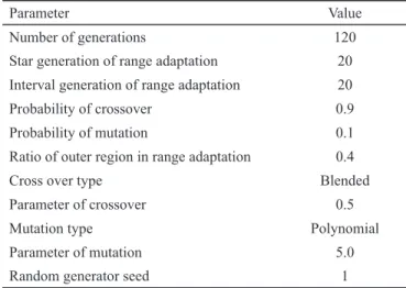
The chosen GA for this optimization was the Adaptive Range Multi-2bjective GA (ARM2GA) (Sasaki and 2 bayas-hi, 2005). This is a type of GA designed for rapid conversion or Pareto Front formation. It employs variable and adaptive range methodologies that in predetermined periods reevaluate the variable boundaries excluding zones that yielded poor results (Fig. 5). The ARM2GA uses the classic GA param-eters, such as mutation, crossover and number of generations, and also the ones for the range adaptation process. The values of these parameters were selected based on several tests and are presented on Table 1. These parameters resulted in the evaluation of 2,519 individuals over the course of 120 generations, although in many of the runs convergence of the majority of the design variables was achieved earlier.
INTERNAL BALLISTICS AND ENGINEERING
MODELS
The ballistic model for the hybrid motor optimization process has its roots on that proposed by Casalino and Pastrone (2005). The main parameters are shown in Fig. 6.
The design of the hybrid rocket engine follows the de¿nition of the initial thrust level, mixture ratio, oxidizer tank pressure, nozzle expansion ratio and the one of throat area to initial port area. Since port area changes as the solid fuel regresses, most of these parameters change during engine operation. The code thus integrates the necessary equations to evaluate the performance of the deboost system along the mission.
Solid fuel regression rate, as a function of the oxidizer mass Àux, is calculated through the relation in Eq. 5:
.
r
aGoxi
n=
o
(5)Values of a and n parameters, appearing in Eq. 1, as proposed by our research group (Bertoldi, 2007) and those of Karabeyoglu et al. (2004) can be seen in Table 2, for nitrous oxide and paraf¿n. The higher regression rate obtained by (Bertoldi, 2007) compared to the latter may be explained by the use of pressure swirl atomizers. For hydrogen peroxide and paraf¿n, as the propellants, we took regression parameters found in Brown and Lydon (2005).
Table 2. Values of a and n, for G in kg/(m2s) and rǜ in mm/s.
Propellants Į n Reference
N22/paraf¿n 0.722 0.67 Bertoldi
(2007)
N22/paraf¿n 0.488 0.62 Karabeyoglu et al.
(2004)
H222/paraf¿n 0.034 0.96 Brown and
Lydon (2005)
Due to the high paraf¿n regression rate compared to other traditional solid fuels for hybrid propulsion systems, only one combustion port is needed. Therefore, the variation of the internal grain diameter (R) versus time is given by Eq. 6:
/ .
dR dt=ro (6)
For pressure variation inside the combustion chamber, we used the following relation in Eq. 7:
Figure 5. 2verview of range adaptation (design range) employed by
the ARM2GA algorithm (Sasaki and 2bayashi, 2005).
Figure 6. Pressure locations and areas for the ballistic model.
Table 1. Initial setting of the ARM2GA algorithm.
Parameter Value
Number of generations 120
Star generation of range adaptation 20
Interval generation of range adaptation 20
Probability of crossover 0.9
Probability of mutation 0.1
Ratio of outer region in range adaptation 0.4
Cross over type Blended
Parameter of crossover 0.5
Mutation type Polynomial
Parameter of mutation 5.0
. / .
p1 1 0 2 A At p pc
2
=6 + ^ h@ (7)
In Eq. 7, p1 is the head end pressure (oxidizer injection plate)
and pc the combustion chamber pressure just before the
expan-sion process (afterburner). Also, Atand Ap refer to the area of the
throat and grain port, respectively. 2xidizer mass Àow rate is a
function of the pressure difference through the injection plate,
and its hydraulic resistance (Zinj) can be estimated by Eq. 8:
/
mooxi= ^pt-p1h Zinj (8)
where,
pt is the oxidizer tank pressure.
The fuel mass Àow rate can be calculated by Eq. 9:
.
mof =ȡfrAo b (9)
The fuel mass Àow rate in Eq. 9 is a function of the
paraf-¿n density (ȡf ), regression rate, and internal burning area of
the combustion port (Ab), respectively. The ratio between mǜR[L
and provides the mixture ratio of oxidizer and fuel, accord-ing to Eq. 10:
/ .
OF=mooxi mof (10)
The throat area, assuming isentropic expansion, as a function of the chamber pressure in the afterburner section is determined with the help of Eq. 11:
* / .
At=^mooxi+m cofh pc (11)
In Eq. 11, the characteristic velocity was calculated through Eq. 12:
(12)
* / .
c
y R T Y
1 2 y y g c 1 1 c = + + + ^ ^ ^ h h h ; E
The products of combustion and relevant thermodynamic properties were estimated assuming chemical equilibrium. The main parameters were obtained after running the rocket propulsion analysis (RPA) code (Ponomarenko, 2010). Chemical equilibrium was applied for the chosen pair of
propellants N22/paraf¿n and H222/paraf¿n systems for
different ratio and pressure levels. The sensitivity of the
reactant products to pressure was considered somehow weak and a mean pressure of 25 bars was chosen for all cases. The data were interpolated accordingly given three polynomials to represent the combustion chamber
tempera-ture, Tc(OF); the average molar mass of the combustion
products; 0:c(OF) and the speci¿c heat ratio, Ȗ(OF) as a
function of the mixture ratio for the propellants combination of interest. These polynomials allow an estimation of the
thrust coef¿cient by Eq. 13:
. C y y y Pc Pe P P P P 1 2 1 2 1 F y y y y C e C 2 1 1 1 0 ! = - + - + -+ -
-c m ; ` j E c m (13)
The parameters needed to infer the thrust coef¿cient are:
speci¿c heat ratio (Ȗ), nozzle exhaust plane pressure (pe),
ambient pressure (p0), and nozzle expansion ratio (İ).
The initial geometry of the engine was obtained after
inferring the initial mass Àow rate of combustion products
and initial thrust (Fi) along with the calculated characteristic
velocity and thrust coef¿cient through Eq. 14:
*
m m m
c C
F ,
t i f oxi i
F i
= + =
o ^ o o
^
h h (14)
The throat area was then calculated by Eq. 15:
/ * .
At=mot i, ^p cc i, h (15)
The throat area was assumed constant during rocket mission. The initial port area was estimated geometrically (Eq. 16):
/ .
Ji=A At p i, (16)
This parameter relates the throat area to the initial port
one Ap i, Di 4
2 $ r
=
^ h of the solid fuel as mean to envelope the
oxidizer mass Àux. The exit area was calculated for ambient
pressure of 0.05 bar and for a mean value of Ȗ. Then, a ¿xed
value of İ was set. The maximum allowed value for İ was 30.
From the initial burning area, it was possible to infer the length of the solid fuel grain, thus characterizing the whole engine.
The instantaneous thrust of the motor can be inferred using
mass Àow rate as in Eq. 17:
* ( ) .
F=c C mF of+mooxi (17)
The complete burn time can be estimated by knowing the instantaneous regression rate, the initial port radius, and the
.
t 1rdR R
R
i f
=
#
o (18)The planned velocity variation of the spacecraft, however, should be completed before the system reaches the limit state, as a way to avoid compromising the mission. The desired velocity variation is obtained by integrating the thrust/mass over time (Eq. 19):
.
V mFdt t
t
i
D =
#
(19)2nce de¿ned the initial engine geometry, the mission perfor-mance is evaluated after integrating the relevant equations. The provided spacecraft velocity reduction is compared to the mission requirement, to assert the feasibility of that individual.
The estimated mass of any given individual (engine) is obtained after summing the mass of the combustion chamber, nozzle, oxidizer tanks, pressurization tank, and solid fuel mass. The mass of valves, ignition system, plumbing and other auxiliary devices were not taking into account in the mass model. The contribution of these components should be added to the total mass estimations after the optimization process. Hence, we considered a 20 addition of the optimized engine candidate mass arguing that the mass of the subsystems (catalytic bead for and other components for the ignition system, plumbing, valves etc) is proportional to the mass of the system. This ¿gure is twice as much of that proposed by Costa and Vieira (2010) on account of the lack of reliable data of the components of the propulsive system. All the tanks and combustion chamber would be made of aluminum reinforced with carbon ¿ber. Mean properties of such composite materi-als were employed in the mass model. The tanks of oxidant, pressurization subsystem, and structure of the combustion chamber were designed using composite material, aluminum reinforced with carbon, with overall density of 1.8 kg/m3 and tensile strength limit of 93 MPa. These structural materials were chosen to allow production following the current tech-nological domain of the Brazilian space industry.
Both the oxidizer and pressurizing tanks were spherical, and they were considered as thin walled pressure vessels. The mass of a spherical pressure vessel is given by the Eq. 20:
.
Mv,1 23p Vv v
v t
= (20)
where,
ȡ and ı are the speci¿c mass and the yielding tension of the tank’s material,
pv and Vv are the design pressure and volume of the stored
Àuid (vessel).
The code adds a 10 volume for the estimated value of this parameter to accommodate changes in the speci¿c volume due to temperature variations.
The combustion chamber is a cylindrical pressure vessel with spherical ends, in which the mass is estimated by Eq. 21:
Mv,2 2 Rv Lv R pv v 2
r
v t
= ^ - h (21)
where,
Rv is the radius of the vessel and Lv its length. The internal diameter of the combustion chamber is equal to the grain external diameter and the vessel’s length should accommodate the solid fuel and the postcombustion chamber (10 the solid fuel length). The spherical ends of the chamber account for the masses of the pre and postcombustion chambers and the convergent part of the nozzle.
The nozzle is modeled as a cone with the same thickness of the combustion chamber. The inclusion of the nozzle mass was intended to penalize large pressure ratios.
For the hydrogen peroxide case, a pressurization subsys-tem was necessary. The pressurization syssubsys-tem mass was calculated based on the methodology presented by Sutton (2001). The gas (He) was assumed to be stored in a spherical carbon reinforced tank and was modeled as thin wall pressure vessel. The storage pressure and temperature of the gas were set at 400 bars and 300 K, respectively.
RESULTS AND DISCUSSION
The optimization code was then applied to help design the
deboost engine based on the proposed con¿gurations. The test
cases are summarized in Table 3. For a given optimized design,
the code determines the initial and ¿nal grain diameters, the
solid fuel length, the chamber pressure, and the oxidizer mass
Àow rate. The results should be seen as a basis for preliminary
Engineering design.
Table 3. 2ptimized motor con¿gurations.
Test case
Type of oxidant
Scheme of oxidant
injection pc [bar] pt [bar]
1 Hydrogen
peroxide Pressurized with He 10 1.3 pc
2 Hydrogen
peroxide Pressurized with He 30 1.3 pc
3 Nitrous
oxide Blowdown 10 1.1 pc
Test case 1
We start presenting the test case 1, based on hydrogen
peroxide (90) with 10-bar minimum combustion chamber
pressure. This low-pressure level was set from a preliminary investigation, which showed that structural mass would penal-ize the overall mass of the system (main objective function).
Low-pressure engine would give a poor speci¿c impulse, but
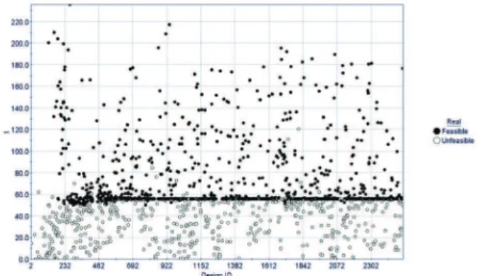
the mission (deboosting) requires a long time deceleration to improve reentry precision, therefore, a high-thrust level is not required and motor performance would not be a primary concern. The optimization process then brings the pressure of the system (~ 10.1 bars) closer to the lower acceptable
limit, as Fig. 7 depicts. The dark symbols in the ¿gure refer
to a feasible engine, while the lighter ones showed unfeasible individuals, the ones that do not meet the design constraints (Delta-V and burning time constraints).
Figure 8 shows the convergence history for the grain external diameter. The convergence after 2,000 individuals approaches an external diameter of the order of 195 mm. At the same time, the suggested grain internal diameter approached 145 mm, as shown in Fig. 9. The burning thickness would be of the order of 25 mm. For a 55.34-second burning time, the expected mean regression rate would be lower than 0.5 mm/s, which could be attained with most of the solid fuels currently available.
Figure 10 presents the converged solution for the solid fuel length. As it can be seen, the system approaches a 488-mm value. The motor itself would claim a much longer room on
account of the volume needed to accommodate the vaporization chamber, after oxidizer injection, the postcombustion chamber as well as the engine nozzle. Consequently, the motor would
pose some dif¿culties in ¿tting the SARA reentry engine bay, if
this type of limitation was put into consideration. In a different arrangement, in which nitrous oxide is the oxidizer, this param-eter should not be a concern, as we will see later in this section. Finally, as a design variable, the result for the initial
Figure 7. Convergence history of the combustion chamber pressure
for case 1.
Figure 8. Convergence history of the solid fuel external diameter for
case 1.
Figure 9. Convergence history of the solid fuel internal diameter for
oxidizer mass Àow rate is presented in Fig. 11. Convergence approaches a value near to 260 g/s of the hydrogen peroxide. This can be easily attained with few pressure swirl atomizers placed at the oxidizer injection plate.
As for mission requirements and assumed constraints, Fig. 12 presents the convergence for spacecraft velocity reduc-tion. Figure 13 shows the optimized motor operating time and Fig. 14, the overall mass of the system. The optimized overall mass of the engine was close to 22 kg. This engine would accomplish the mission with a velocity reduction of 235 m/s
attained in near 55 seconds of burning time. This optimized engine mass is much lower than those calculated for liquid and solid propellant rockets (Villas Bôas et al., 2000). These
results imply that high-engine speci¿c impulse could be considered of secondary relevancy for the reentry mission.
Figure 15 shows the inÀuence of all the design variables on the engine constraints and mission requirements. A signi¿ -cant inÀuence on the velocity reduction (Delta-V) comes
from the initial oxidizer mass Àow rate and the geometric parameters of the motor in the following order: solid fuel external diameter; solid fuel initial diameter, and solid fuel length. Thus, combustion chamber pressure claims a very weak inÀuence on this mission requirement. The same trends can be observed for the thrust time (impulse): a rather strong inÀuence on initial mass Àow rate of oxidizer closely followed by the grain external diameter. Engine internal pressure, grain internal diameter and length somewhat share the remaining percentage of the inÀuence. The total mass of the propulsive system is inÀuenced, mainly, by the ¿nal geometric con¿ gura-tion (external and internal grain diameters) and mass Àow rate of hydrogen peroxide. Combustion chamber pressure also causes weak inÀuence on the overall mass of the propulsive
Figure 10. Convergence history of the solid fuel length for Case 1.
Figure 11. Convergence history of the initial mass Àow rate of
oxidizer for case 1.
Figure 12. Convergence history of the velocity reduction for case 1.
Figure 13. Convergence history of the engine burning time for case 1.
Figure 14. Convergence history of the engine overall mass (without
system. For the objective function (overall mass), combustion
chamber pressure has a stronger inÀuence on burning time and
on velocity reduction. The operational envelope of the engine,
as far as OF ratio is concerned, is largely inÀuenced by the
initial oxidizer mass Àow rate and the grain external diameter.
Conversely, the inÀuence on the OF ratio is somehow shared
among the remaining geometric parameters, in addition to the
combustion chamber pressure. Finally, the inÀuence of initial
oxidizer mass Àow rate along with the geometric parameters
of the motor on the burning time show relatively comparable
levels. The inÀuence of the combustion chamber pressure on
the solid fuel burning time can be considered negligible.
Test case 2
In order to evaluate the engine design inÀuence on the
overall mass of the propulsive system, following mission requirements, a much higher combustion chamber pressure was imposed to the constraint of minimum operating
pres-sure of the engine, based on hydrogen peroxide (90). The
optimized solution presented the following design variables and operating conditions of the engine:
solid fuel external diameter – Df = 172 mm;
solid fuel length – Lg = 406 mm;
internal port diameter – Di = 123 mm;
initial combustion chamber pressures – pc,i 30 bar; and
initial oxidizer mass Àow rate mǜR[L = 260 g/s.
These ¿gures are somehow close to those of test case 1,
except the three-fold higher minimum operational combustion chamber pressure. As a consequence, a minor reduction in the
burning time (1.2) occurred, followed by a corresponding
increase for the thrust engine level (~14), a negligible
reduc-tion in the speci¿c impulse (3.4) and, at least, a two-fold
increase in the expansion rate. Figure 16 shows the inÀuence
of the design variables on the engine constraints and on the mission requirements. As the combustion chamber pressure
was increased, the inÀuence of most design variables on the
velocity reduction is of the same level, with the grain internal diameter showing the least share. The same trend holds to the engine burning time and overall mass. The combustion
chamber pressure has also a considerable inÀuence on the OF
ratio, which was not observed for the optimized engine from the other cases. As a whole, this case resulted in an engine
slightly heavier than that of case 1 con¿guration. Due to the
fact that the only difference between the engine con¿guration,
for cases 1 and 2, was the combustion chamber pressure, one could conclude that engine thrust, for the required mission, is not a primary design concern.
Test case 3
Nitrous oxide has a high saturation pressure at ambient temperature (25°C). This self-pressurization characteristic of the oxidizer could be explored in this design assessment.
Therefore, Test case 3 investigates a system con¿guration
based on nitrous oxide and on solid paraf¿n propellants
for the reentry engine of the SARA platform. Basically, the constraints for this case are the same as those imposed to the case 1 study, with the exception of a total absence of any
pres-surization subsystem. 2xidizer injection will take place on
account of the N22 self-pressurization inside the oxidizer tank
by means of a series of pressure swirl atomizers. As oxidizer
depletion takes place, a signi¿cant decay in the tank pressure
is expected. This blowdown process was modeled based on
the assumption of quasi-steady state for Àuid exhaustion.
Figure 17 shows the inÀuence of design parameters on
mission requirements and the objective function. For this
Figure 15. InÀuence of design variables on engine constraints and
objective function for case 1.
Figure 16. InÀuence of design variables on engine constraints and
con¿guration, the inÀuence of pressure on overall mass of the engine, velocity reduction as well as burning time, is of the same order as those from the geometric parameters of the engine.
This con¿guration causes a strong difference on the mission execution and system design when compared to the use of hydrogen peroxide supported by a pressurization subsystem.
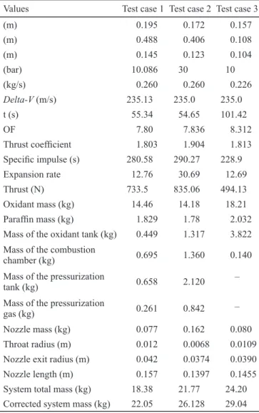
Table 4 presents the main parameters of this optimized con¿guration along with the results for cases 1 and 2. The important differences could be observed for solid fuel length, burning time, speci¿c impulse, thrust, mass of oxidant, and total mass of the engine. The remaining parameters, as show in Table 5, are somewhat similar among any of the hydrogen peroxide con¿gurations.
Table 5 summarizes the explored technologies that may execute the reentry maneuver of the SARA platform. Relevant parameters were investigated and compared among different motor con¿gurations, three from a previous study (Villas Bôas
et al., 2000) and one selected from this work. The optimized
hybrid propellant rocket con¿guration seems to be a very attractive technological solution for the reentry system, on account of the inherent aforementioned advantages over solid and liquid counterparts and, more importantly, the resulted lower mass of the engine.
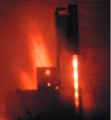
Figure 18 shows a hybrid rocket engine operating in a test stand. The engine makes use of nitrous oxide and paraf¿n as the propellants. Following the large external diameter, the burning time of such motor would match that calculated for case 3, for an equivalent thrust. Some level of thrust variation was accomplished in this test campaign, suggesting a much less effort on developing such solution for the SARA platform.
Table 4. Deboost engine system for the three test cases.
Values Test case 1 Test case 2 Test case 3
(m) 0.195 0.172 0.157
(m) 0.488 0.406 0.108
(m) 0.145 0.123 0.104
(bar) 10.086 30 10
(kg/s) 0.260 0.260 0.226
Delta-V (m/s) 235.13 235.0 235.0
t (s) 55.34 54.65 101.42
2F 7.80 7.836 8.312
Thrust coef¿cient 1.803 1.904 1.813
Speci¿c impulse (s) 280.58 290.27 228.9
Expansion rate 12.76 30.69 12.69
Thrust (N) 733.5 835.06 494.13
2xidant mass (kg) 14.46 14.18 18.21
Paraf¿n mass (kg) 1.829 1.78 2.032
Mass of the oxidant tank (kg) 0.449 1.317 3.822
Mass of the combustion
chamber (kg) 0.695 1.360 0.140
Mass of the pressurization
tank (kg) 0.658 2.120
–
Mass of the pressurization
gas (kg) 0.261 0.842 –
Nozzle mass (kg) 0.077 0.162 0.080
Throat radius (m) 0.012 0.0068 0.0109
Nozzle exit radius (m) 0.042 0.0374 0.0390
Nozzle length (m) 0.157 0.1397 0.1455
System total mass (kg) 18.38 21.77 24.20
Corrected system mass (kg) 22.05 26.128 29.04
Table 5. Analysis of the proposed technologies for the SARA
platform reentry system.
Parameter LBP
engine*
LMP engine*
SP
engine* HP engine
Mass High –
47 kg
Middle – 40 kg
Low – 35.1 kg
Low – 20 kg
Technical
challenges High High Low Low
Development
status Low Middle High Middle
Production cost High Middle Low Low
2perating
precision High High Low High
Handling, safety,
and toxicity High care High care
Middle
care Low care
LBP: liquid bipropellant; LMP: liquid monopropellant; SP: solid
propellant; HP: hybrid propellant. *Villas Bôas et al. (2000).
CONCLUSIONS
2ptimized hybrid propellant rocket engines, based on three different con¿gurations, were proposed as main components of the deboost system of the Brazilian SARA platform. All three con¿gurations resulted in engines lighter than the liquid and solid motors previously studied. The inherent advantages of hybrid propulsion system, over more traditional counterparts, should be taking into consid-eration following this assessment. Hybrid rocket technology would increase system reliability for the required mission, considering that the propulsive components are readily available in the Brazilian space industry at very competi-tive cost. The optimization process discussed in this work can be considered an essential tool for the preliminary phase design of hybrid rocket propulsive systems for a given application.
ACKNOWLEDGEMENTS
The authors thank the Agência Espacial Brasileira (Programa Uniespaço) and Conselho Nacional de Desenvolvi-mento Cientí¿co e Tecnolygico (CNPq) for their support.
REFERENCES
Akhtar, S.and Lin-shu, H., 2007, “2ptimization and Sizing for Propulsion System of Liquid Rocket Using Genetic Algorithm”,
Chinese Journal of Aeronautics, Vol. 20, No. 1, pp. 40-46.
Almeida, L. A. R. and Santos, L. M. C., 2005, “Design, fabrication and launch of a hybrid rocket with paraf¿n and N22 propellants” (In Portuguese),Graduation Project, Mechanical Engineering Department, University of Brasília, Brasília, D. F., Brazil, 83p.
Altman, D. and Holzman, A., 2007, “2verview and History of Hybrid Rocket Propulsion.” In Chiaverini, M.J., Kuo, K.K. (ed.), Fundamentals of Hybrid Rocket Combustion and Propulsion, American Institute of Aeronautics and Astronau-tics, Inc., Reston, Virginia, Vol. 218, Chapter 1, pp. 01-36.
Anderson, M.B., 2002, “Genetic Algorithms In Aerospace Design: Substantial Progress Tremendous Potential.” Paper presented at the RT2 AVT Course on “Intelligent Systems for Aeronautics”, held in Rhode-Saint-Genèse, Belgium, 13-17 May 2002, and published in RT2-EN-022.
Bertoldi, A. E. M., 2007, “Experimental investigation of the burning of paraf¿n and nitrous-oxide in hybrid rocket engines (In Portuguese), Master Thesis, Mechanical Engi-neering Department, University of Brasília, Brasília, D. F., Brazil, 115p.
Brown, T. R. and Lydon, M. C., 2005, “Testing of Paraf¿ n-Based Hybrid Rocket Fuel Using Hydrogen Peroxide 2xidizer”, AIAA Region 5 Student Conference, Wichita, USA.
Campbell, J.et al., 2008, “Handling considerations of nitrous oxide in hybrid rocket motor testing”, Proceedings of AIAA 2008-4830 44th AIAA/ASME/SAE/ASEE Joint Propulsion Conference & Exhibit, Poway, California, pp. 3177-3183.
Casalino, L. and Pastrone, D., 2005, “2xidizer Control and
2ptimal Design of Hybrid Rockets for Small Satellites.” Journal of Propulsion and Power, Vol. 21, pp. 230-238.
Contaifer, R. A., 2006, “4uali¿cation and Àight tests of the SD-1 sounding rocket” (In Portuguese), Graduation Project, Mechanical Engineering Department, University of Brasília, Brasília, D. F., Brazil, 75p.
Costa, F.S. and Vieira, R., 2010, “Preliminary Analysis of Hybrid Rockets for Launching Nanosats into LE2”, ABCM, Vol. 32, No. 4, pp. 502-509.
DaLin, R. et al., 2012, “Design and 2ptimization of Variable Thrust Hybrid Rocket Motors for Sounding Rockets, Science China”, Technological Sciences, Vol. 55, No. 1, pp. 125-135.
Davydenko, N. A. et al., 2007, “Hybrid rocket engines – the bene¿ts and prospects”, Aerospace Science and Technology, Vol. 11, pp. 55-60.
Greatrix, D.R., 2009, “Regression rate estimation for standard-Àow hybrid rocket engines”, Aerospace Science and Technology, Vol. 13, pp. 358-363.
Karabeyoglu, M. A. et al., 2004, “Scale-up Tests of High Regression Rate Paraf¿n-BasedHybrid Rocket Fuels.”, Jour-nal of Propulsion and Power, Vol. 20, No. 6, pp. 1037-1045.
Karabeyoglu, M. A., 2008, “Hybrid propulsion for future space launch”, 50th Anniversary Symposium and Celebration, University of Stanford Aero/Astro Symposium, Palo Alto, California.
Koldaev, V. and Moraes, P. Jr., 1997, “Design of a recovery system for small orbital payloads”, Proceedings of the 14th Brazilian Congress of Mechanical Engineering, Bauru, São Paulo, Brazil.
Kwon, S. T. et al., 2003, “2ptimal design of hybrid motor for the ¿rst stage of air launch vehicle”, Proceedings of the 39th AIAA/ASME/SAE/ASEE Joint Propulsion Conference and Exhibit, Huntsville, Alabama.
2iknine, C., 2006, “New perspectives for hybrid propulsion”, Proceedings of the AIAA paper 2006-4674, 42nd AIAA/
ASME/SAE/ASEE Joint Propulsion Conference and Exhibit, Sacrameno, California.
Rhee, I.et al., 2008, “2ptimal Design for Hybrid Rocket engine for Air Launch Vehicle”, Journal of Mechanical Science and Technology, Vol. 22, pp. 1576-1585.
Santos, L. M., C. et al., 2006, “Experimental investigation of a paraf¿n based hybrid rocket”, Thermal Engineering, Vol. 5, No. 1, pp. 08-12.
Sasaki, D. and 2bayashi, S., 2005, ³(I¿FLHQW 6HDUFK IRU 7UDGHRIIVE\$GDSWLYH5DQJH0XOWL2EMHFWLYH*HQHWLF$OJR
-rithms”, Journal of Aerospace, Computing, Information and
Communication, Vol. 2, pp. 44-64.
Sutton, G. P., 2001, “Rocket propulsion elements: an intro-duction to the engineering of rockets”, 7th edition, New York,
USA, John Wiley & Sons,
Viegas, F. L. and Salemi, L. C., 2000, “Design and assem-bling of a static test bench for hybrid rocket engines” (In Portuguese), Graduation Project, Mechanical Engineering Department, University of Brasília, Brasília, D.F.
Villas Bôas, D. J. F.et al., 2000, “Studies on the characteristics of de-boost motors for a small recoverable orbital platform”, Proceedings of the National Congress of Mechanical Engi-neering, Natal, R.N., Brazil.