INTRODUCTION
As a consequence of the technological advances, the use of electromagnetic radiation in the microwave range has become intense in the last years. The telecommunication area has contributed intensively for this with a wide variety of commer-cially available artifacts, for example: cellular telephones, reception/transmission antennas and safety systems used in apparatus of aircraft, ships and vehicles in general. Then, the electromagnetic radiation noise level in different environment systems has increased continuously (Dias, 2000).
Aiming to eliminate or reduce the spurious electromag-netic radiation levels in different applications, the research and the development of radar absorbing materials (RAM) have increased. RAM makes use of energy-exchange proper-WLHVRIDQ\VSHFL¿FGLHOHFWULFDQGPDJQHWLFLURQFRPSRXQGV which are able to transform the electromagnetic radiation in
heat, in determined frequency bands. The attenuation of the electromagnetic wave can also be favored by the adequate combination of the phase canceling phenomenon by adjusting the electrical thickness of RAM (Faez et al., 2005; Dias, et al., 2005; Folgueras, et al., 2007; Gama et al., 2011; Pinto and Rezende, 2012). The following applications are among the most important for the RAM area: (a) to improve patterns of DQWHQQDVEWRUHGXFHXQGHVLUDEOHUHÀHFWLRQVIURPREMHFWVDQG devices, (c) to cover inside test rooms (anechoic chambers) in order to achieve “free space” conditions for measurements of components and systems, (d) to reduce the radar cross section (RCS) of targets, (e) to achieve both “free space” termination and waveguide and coaxial termination (dummy loads), and (f) to improve the shielding of enclosures and containers when used as gasket materials.
In general, microwave absorbers are processed using different polymeric matrices. Among them, polyisoprene, neoprene or silicon rubber sheets or epoxy, phenolic or polyurethane (PU) coatings, loaded with carbon and/or iron particles and/or ferrites and/or conducting polymers can be
5HÀHFWLYLW\RI+\EULG0LFURZDYH$EVRUEHUV%DVHGRQ1L=Q
)HUULWHDQG&DUERQ%ODFN
-RVLDQHGH&DVWUR'LDV1,QiFLR0DOPRQJH0DUWLQ10LUDEHO&HUTXHLUD5H]HQGH2,* 1 Instituto Tecnológico de Aeronáutica - São José dos Campos/SP – Brazil
2 Instituto de Aeronáutica e Espaço - São José dos Campos/SP – Brazil
Abstract: This study had as main objective to show that the adequate combination of magnetic and dielectric particles
can improve the radar absorbing materials performance. For this, formulations of polyurethane resin loaded with carbon black and NiZn ferrite, with general composition MFe2O4, where M = Ni, Zn or both elements, homogenized E\FRQYHQWLRQDOPHFKDQLFDOPL[WXUHZHUHSUHSDUHG5HÀHFWLYLW\PHDVXUHPHQWVRIGLIIHUHQWFRDWLQJIRUPXODWLRQV DSSOLHGRQDOXPLQXPÀDWSODWHVPPWKLFNQHVVZHUHSHUIRUPHGXVLQJWKH1DYDO5HVHDUFK/DERUDWRU\DUFK WHFKQLTXHLQWKH;EDQGIUHTXHQF\UDQJH;UD\GLIIUDFWLRQDQGPDJQHWLFVXVFHSWLELOLW\HYROXWLRQDQDO\VHVRIWKHWHVWHG IHUULWHVKRZHGWKDWWKLVPDJQHWLFDGGLWLYHSUHVHQWVGLIIHUHQWSKDVHV$WWHQXDWLRQYDOXHVRIaG%aRIWKHZDYH DEVRUSWLRQIRUWKHSRO\XUHWKDQHFDUERQEODFNIHUULWHIRUPXODWLRQLQZWUHVSHFWLYHO\ZHUHIRXQG7KLVORZ DWWHQXDWLRQYDOXHVaG%LVDWWULEXWHGWRWKHSUHVHQFHRIGLIIHUHQWSKDVHVLQWKH1L=QIHUULWHDVVKRZQE\ERWKWKH ;UD\SDWWHUQDQGWKHPDJQHWLFVXVFHSWLELOLW\DQDO\VHVDQGDOVRWRWKHWKLFNQHVVDQGWKHDGGLWLYHVFRQFHQWUDWLRQXVHG As main result, this study shows that the adequate combination of carbon black and NiZn ferrite improves the processed radar absorbing materials performance due to the adequate adjustment of the impedance matching, which favors the PLFURZDYHDEVRUEHUHOHFWURPDJQHWLFZDYHLQWHUDFWLRQ
Keywords: Coatings, Radar absorbing materials, RAM, NiZn ferrites, Carbon black.
Received: 24/04/12 Accepted: 04/07/12 *author for correspondence: [email protected]
Pç. Mal. Eduardo Gomes, 50. CEP: 12.228-901 – São José dos
cited. Usually, these materials need to attend the following UHTXLUHPHQWV ORZ ZHLJKW JRRG ZHDWKHUDELOLW\ JRRG ÀH[-ibility, minimum thickness, wide operational band with low UHÀHFWLRQH[WUHPHWHPSHUDWXUHFDSDELOLW\ORZRXWJDVVLQJDQG low cost (Dias et al., 2005; Gama and Rezende, 2010).
5$0&+$5$&7(5,67,&6
Unique materials and electrical designs are used to attenu-ate or essentially trap radar signals. The radar transparency DQGWKHUHÀHFWLYLW\DUHIXQFWLRQQRWRQO\RIWKHWDUJHW¶VVKDSH but also of the electrical and magnetic properties of the used material and the characteristics related to the incident radar signal. The low detection (LO) characteristics of a structure depend on the material properties, particularly their magnetic (permeability) and dielectric (permittivity) properties. Experi-mentally this study considers the cumulative effects of the losses, relating indirectly the absorption phenomena with the SHUPLWWLYLW\DQGSHUPHDELOLW\E\UHÀHFWLYLW\PHDVXUHPHQWV using the Naval Research Laboratory (NRL) arch technique. These physical parameters are given by Eq. 1 and 2 (Cullity, 1972; Lee, 1991; Dias, 2000):
Hr = H’r+ i H”r , (1)
Pr = P’r + i P”r (2)
where Hr and Pr are the relative permittivity and
permeabil-ity, respectively, which are normalized by the values in the vacuum H e P.
The real parts, H’r and P’r, are related to the stored energy, while the imaginary parts H”r and P”r to the losses. Consider-ing that in dielectric absorbers the loss mechanisms are related to the material conductivity, V, is convenient to express H”r, as (Cullity, 1972; Dias, 2000):
H”r = VZH (3)
where Z is the radiation angular frequency.
The dielectric and magnetic loss tangents are given as Eq. 4 and 5, respectively:
tan G = H”rHr’ (4)
tan Gm = P”rP’r (5)
The refraction index, n, is the relation between the wave number k, characteristic of the wave propagation within the material, and the wave number k related to the wave propaga-tion in vacuum, Eq. 6 (Cullity, 1972; Dias, 2000):
/
n=k k0= n fr r (6)
where k0= ~ n f0 0
/LNHZLVHWKHUHODWLYHSHUPLWWLYLW\DQGSHUPHDELOLW\GH¿QH the intrinsic impedance Z of the material, Eq. 7:
/
Z Z= 0 nr fr (7)
where Z0 is the impedance in vacuum, equal to 377 :.
7KHLQWULQVLFLPSHGDQFHLVWKHYDOXHµREVHUYHG¶E\WKH electromagnetic wave, that impinges the material surface in normal incidence. In practical applications a dielectric mate-rial is applied on a conductor surface and the normalized impedance K is given by Eq. 8 (Cullity, 1972; Dias, 2000):
/ tg k d
r r 0 r r
h= n f ^- n fh (8)
where d is the dielectric layer thickness of material.
The normalized impedance may be used to calculate the UHÀHFWLRQFRHI¿FLHQWR, Eq. 9.
R
1 1
h h
= +
-(9)
where R is a complex number between 0 and 1.
7KLVUHÀHFWLRQFRHI¿FLHQWPD\DOVREHH[SUHVVHGLQGHFL-bels (dB), Eq. 10.
log
I dB^ h=20 10 R (10)
¿HOGVWKH\DUHFDOOHGK\EULGDEVRUEHUV'LDV5H]HQGH et al.; 2004; Dias et al., 2005; Martins et al., 2006).
5$0 HI¿FLHQF\ FDQ EH DYDLODEOH E\ PHDVXUHPHQWV RI IUHHVSDFHUDGDUUHÀHFWLRQFRHI¿FLHQWRIÀDWVDPSOHVXVLQJ the NRL arch technique (Smith et al., 1994; Dias, 2000). The UHÀHFWLYLW\UHGXFWLRQRIHOHFWURPDJQHWLFUDGLDWLRQLQG%LV correlated with the percentage of absorbed energy, as shown in Table 1 (Lee, 1991; Dias, 2000).
7DEOH 5HODWLRQVKLSEHWZHHQUHÀHFWLYLW\UHGXFWLRQDQGWKHDEVRUEHG
energy (Lee, 1991).
5HÀHFWLYLW\UHGXFWLRQG% Absorbed energy, %
0 0
-3 50
-10 90
-15 96.9
-20 99
-30 99.9
-40 99.99
Although permittivity and permeability measurements are useful to support the RAM processing, as shown previously in Eq. 6 to 8, the present study is based on UHÀHFWLYLW\PHDVXUHPHQWVXVLQJWKH15/DUFKWHFKQLTXH This type of measurements has a direct correlation with the permittivity, permeability and impedance parameters of the studied material, as depicted previously (Eq. 6 to 10). In WKLVFRQWH[WWKLVZRUNLQYROYHVUHÀHFWLYLW\PHDVXUHPHQWV using the NRL arch technique, in the X-band frequency range, of different formulations of hybrid RAM based on NiZn ferrite and carbon black (CB) loaded in PU resin. Thus, the main objective of this study was to evaluate the mixture of dielectric (CB) and magnetic (NiZn ferrite) on the RAM performance.
(;3(5,0(17$/
&RDWLQJVSUHSDUDWLRQ
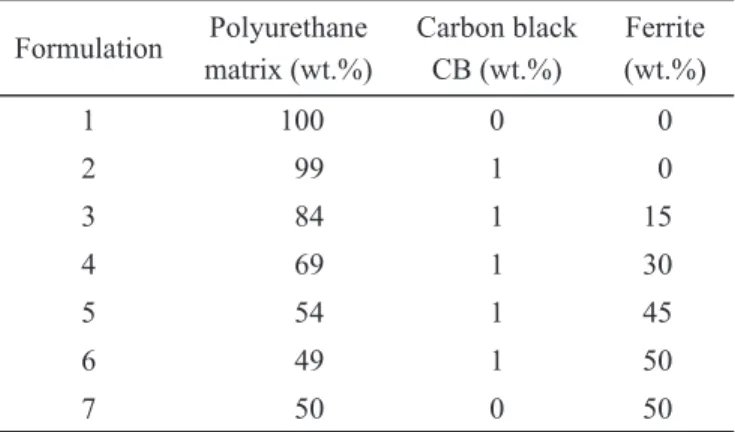
Formulations of a commercial polyester PU resin (two components: resin and catalyst, both colorless, at 1:1 rate) ORDGHGZLWKGLHOHFWULFDQGPDJQHWLF¿OOHUVZHUHSUHSDUHGDV depicted in Table 2.
Table 2. The coating formulations prepared.
Formulation Polyurethane matrix (wt.%)
Carbon black CB (wt.%)
Ferrite (wt.%)
1 100 0 0
2 99 1 0
3 84 1 15
4 69 1 30
5 54 1 45
6 49 1 50
7 50 0 50
Mechanical stirring at 500 rpm were used. The used GLHOHFWULF¿OOHUZDV&%W\SH;&ZLWKSDUWLFOHPHGLXP size of 12 nm and bulk density of 0.26 g/cm3, supplied by Cabot Company, used as received (Cabot, 2004). The PDJQHWLF ¿OOHU ZDV 1L=Q IHUULWH IURP ,0$* %UD]LOLDQ Industry of Ferrites, with nominal formula Ni1-xZnxO.Fe2O3, with x = 0.50, density of 5.01 g/cm3 and particle average size of 4.4 Pm, determined by using a Sharples Micromerograph equipment. After mechanical stirring homogenization, the IRUPXODWLRQVZHUHDSSOLHGRQDOXPLQXP$OÀDWVXUIDFHV (30 × 30 cm), positioned in the horizontal, using conven-tional painting techniques. The complete polymerization of coatings was obtained at 60ºC, for 40 minutes. The average thickness of coatings was 1.0 ± 0.1 mm.
)HUULWHVFKDUDFWHUL]DWLRQ
The crystallographic structure of the NiZn ferrite was determined by X-ray diffraction analyses, using a Philips diffractometer model PW 1830, operated at 40 kV tension and 20 mA current. The magnetic susceptibility evolution of the NiZn ferrite was carried out using thermal-magnetic HTXLSPHQW DW DSSDUHQW PDJQHWLF ¿HOG RI $P UPV DW frequency of 333 Hz, in argon atmosphere.
5HÀHFWLYLW\PHDVXUHPHQWVE\XVLQJ15/DUFKWHFKQLTXH
launched from the transmitter horn travels and impinges the VDPSOH7KHHOHFWURPDJQHWLFZDYHUHÀHFWHGIURPWKHVDPSOH surface travels and is collected by the receiver horn. The far ¿HOGFRQGLWLRQZDVWDNHQLQWRDFFRXQWLQWKHVHPHDVXUHPHQWV Pyramidal absorber is placed around the NRL arch to eliminate undesirable spurious microwave energy that travels around the sample. Measurements were carried out at room temperature RYHUWKHIUHTXHQF\UDQJHWR*+]XVLQJDSROLVKHG$OÀDW SODWHDVWKHUHIHUHQFHPDWHULDO7KHUHIHUHQFHPDWHULDOUHÀHF-WLYLW\LVFRQVLGHUHGDVRIUHÀHFWLRQ.QRWWet al., 1993; %DODQLV'LDV7KHUHÀHFWLYLW\PHDVXUHPHQWVZHUH standardized using reference-absorbing materials purchased from Emerson & Cumming Inc. These absorbers consist of 2 to 20 mm-thickness PU foam plates, loaded with carbon particles (Jauman absorbers). These microwave absorbers are usually used to recover the interior of anechoic chambers. The errors of WKHUHÀHFWLYLW\PHDVXUHPHQWVZHUHH[SHULPHQWDOO\GHWHUPLQHG FRPSDULQJWKHREWDLQHGUHIHUHQFHUHÀHFWLYLW\FXUYHVZLWKWKDW one furnished by Emerson & Cumming Inc. supplier. The determined errors stay below 1% in the frequency range of 8 to 12 GHz (Dias, 2000; Rezende et al., 2003).
5(68/76$1'',6&866,216
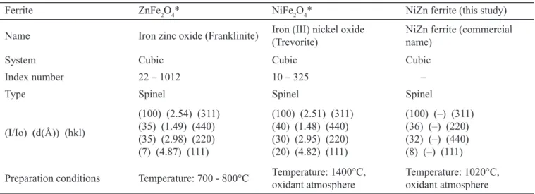
Figure 1 shows the X-ray patterns of the NiZn ferrite used in the present study. Table 3 compares the pattern obtained for the NiZn ferrite with those of ZnFe2O4 and NiFe2O4 ferrites from the literature (JCPDS, 2008).
Comparing the X-ray patterns of ZnFe2O4 and NiFe2O4 ferrites, from literature, it is possible to observe that the d(Å)
and hkl values are very close, showing that these ferrites can present different phases with similar crystallographic param-eters. Correlating these values with those obtained from the tested NiZn ferrite, it is possible to observe that this sample has DPL[WXUHRISKDVHVPDNLQJGLI¿FXOWWRDVVXPHWKDWWKHWKUHH strongest lines in the pattern of the analyzed sample are due to the NiZnFe2O4. From these analyses, it can be concluded that the ferrite used in this study presents the general formula MFe2O4, where M can be substituted for Ni, Zn or both elements.
According to the literature (Verwey and Helmann, 1947; Cullity, 1972; Marcel Dekker, 1990; Valenzuela, 1994; Dias, 2000), the chemical composition of the studied NiZn ferrite indicates that this one belongs to the spinel class, with the possibility of application as microwave absorbing center in RAM processing (Cho et al., 1996; Dias, 2000).
Figure 1. X-ray pattern of NiZn ferrite studied.
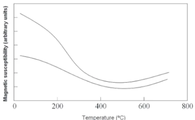
Figure 2 shows the magnetic susceptibility evolution curves of the studied NiZn ferrite. It is observed that the NiZn
Table 3. Comparison of the patterns of NiZn, Zn and Ni ferrites.
Ferrite ZnFe2O4* NiFe2O4* NiZn ferrite (this study)
Name Iron zinc oxide (Franklinite) Iron (III) nickel oxide (Trevorite)
NiZn ferrite (commercial name)
System Cubic Cubic Cubic
Index number 22 – 1012 10 – 325 –
Type Spinel Spinel Spinel
(I/Io) (d(Å)) (hkl)
(100) (2.54) (311) (35) (1.49) (440) (35) (2.98) (220) (7) (4.87) (111)
(100) (2.51) (311) (40) (1.48) (440) (30) (2.95) (220) (20) (4.82) (111)
(100) (–) (311) (36) (–) (220) (32) (–) (440) (8) (–) (111)
Preparation conditions Temperature: 700 - 800°C Temperature: 1400°C, oxidant atmosphere
Temperature: 1020°C, oxidant atmosphere
ferrite does not show magnetic transitions. Then, the Curie WHPSHUDWXUH LV QRW GH¿QHG FRQ¿UPLQJ WKDW WKH DQDO\]HG sample is constituted of a mixture of different phases.
Figure 2. Magnetic susceptibility evolution curves of NiZn ferrite
studied.
)LJXUHVKRZVWKHUHÀHFWLYLW\FXUYHRIWKHSXUH38PDWUL[ (formulation 1, Table 2) applied on Al plate and also the Al plate curve used as reference. These curves are nearly cover-ing one another, showcover-ing that the pure PU matrix applied on the Al plate does not contribute to reduce the incident signal, in the 8 to 12 GHz range. This behavior guarantees that the PU resin used in coating formulations does not interfere in WKH UHÀHFWLYLW\ PHDVXUHPHQWV (DFK UHÀHFWLYLW\ FXUYH ZDV obtained, in the interval of 8 to 12 GHz, with 400 points.
)LJXUH5HÀHFWLYLW\FXUYHVRIWKHSXUHSRO\XUHWKDQHSRO\PHUDQG WKHDOXPLQXPÀDWSODWHUHIHUHQFH
)LJXUHSUHVHQWVWKHUHÀHFWLYLW\FXUYHVRIWKHIRUPXOD-WLRQVWR7DEOHDSSOLHGRQ$OÀDWSODWHV)LJXUHD shows that the PU/CB formulation, in proportion of 99/1 (wt.%), respectively, does not contribute to attenuate the incident electromagnetic wave. Figure 4b, representative of the PU/CB/NiZn ferrite (84/1/15, wt.%) formulation, shows a slight displacement between the reference curve and
that one obtained for this formulation. Figure 4c to Fig. 4e show that the ferrite amount increase from 30 to 50% (wt.%) in the PU formulation promotes the curves debonding with the consequent increase of the attenuation values, from 1 to 4 dB, in the frequency range of 8 to12 GHz, respectively. Figure 4d shows higher attenuation values for frequencies above 9 GHz. Figure 4e is typical for RAM named broad-band type (Afsar et al., 1986; Dias, 2000). Figure 4f (formulation 7 based on PU/ferrite, 50/50 wt.%) shows the attenuation values decreasing (§ 2 dB), when compared to those determined for formulation 6, which contains simulta-neously CB and ferrite.
Correlating the results, it is possible to conclude that the formulation containing only CB particles does not contribute to attenuate the incident radiation in the 8 to 12 GHz range. Similar behavior is observed for formulation 7, containing only the studied NiZn ferrite. Comparing the UHÀHFWLYLW\YDOXHVZLWKWKDWRQHIURPOLWHUDWXUH5H]HQGH et al., 2001; Soto-Oviedo et al.LWLVDOVRYHUL¿HGWKDW the processed RAM samples present low performance (up to 4 dB). This behavior is attributed probably to the presence of different phases in the NiZn ferrite, as determined by X-ray diffraction and magnetic susceptibility evolution analyses and, also, to the frequency range (8 to 12 GHz) adopted in WKHUHÀHFWLYLW\PHDVXUHPHQWVWKHFRDWLQJWKLFNQHVVDQGWKH additives concentration used.
Higher attenuation values are obtained when both addi-tives (ferrite and CB) are loaded simultaneously within the PU matrix. This behavior is attributed to the great difference between the density values of both additives (0.14 and 5.01 g/cm3 for CB and NiZn ferrite, respectively). This density difference promotes a heterogeneous distribution of the SDUWLFOHVLQWRWKHFRDWLQJOD\HUDSSOLHGRQWKH$OÀDWSODWH Considering that the Al plate was kept horizontal during the application of the formulations, the heavier particles (NiZn ferrite) moved towards the Al plate. Consequently, the outer surface of the coating makes richer in lighter particles (CB). This feature observed in hybrid coating induced a better adjustment of the impedance of the material with the air. In this condition, the wave propagation into the mate-ULDO LV IDYRUHG DQG WKH 5$0 HI¿FLHQF\ LV LPSURYHG DV mentioned previously in Eq. 7 and 8 (Cullity, 1972; Dias, 2000).
the electromagnetic radiation in heat. Ohmic loss can be promoted by carbon particles and the ferrite particles can favor spin inversion, and it is known that both phenomena lead to the wave energy attenuation. The electromagnetic wave attenuation can also be improved by adjusting the elec-tric thickness of the RAM which favors the wave attenuation E\ ZDYH SKDVH FDQFHOLQJ /HH .QRWWet al., 1993; Rezende et al., 2001; Rezende et al., 2002).
&21&/86,216
This study showed that the adequate combination of CB and NiZn ferrite in PU formulations allowed obtaining RAM with better performance compared to those prepared with CB or NiZn ferrite separately. The better performance of the hybrid RAM is attributed to an adequate adjustment of the impedance of the material with the air, which favors
(a) (b)
(c) (d)
(e) (f)
)LJXUH5HÀHFWLYLW\FXUYHVRIWKHIRUPXODWLRQV&XUYHLQEODFNLVWKHUHIHUHQFH$OSODWHDQGFXUYHVLQUHGUHIHUWRWKHSUHSDUHGIRUPXODWLRQV
the RAM-electromagnetic wave interaction. This optimized condition is a consequence of the heterogeneous distribution of the particles (with different density values) in the coating layer. Attenuation values of ~4 dB for the PU resin/CB/NiZn ferrite formulations (49/1/50 wt.%, respectively) were obtained.
$&.12:/('*(0(176
The authors thank São Paulo Research Foundation (FAPESP) – project N°. 97/14055-7, National Counsel of 7HFKQRORJLFDODQG6FLHQWL¿F'HYHORSPHQW&13T±SURMHFW N°. 305478/2009-5, the (VWDGR0DLRU GD $HURQiXWLFD (0$HUIRUWKH¿QDQFLDOVXSSRUWDQG$GULDQR/XL]GH3DXOD for the valuable discussions on the subject.
5()(5(1&(6
Afsar, M. N. et al., 1986, “The measurement of the proper-ties of materials”. Proceedings of the IEEE, Vol. 74, N°. 1, pp. 183-199.
Balanis, C. A., 1997, “Advanced Engineering Eletromagnet-ics”. New York: John Wiley Sons.
Cabot Co., USA, 2004, “Data Sheet: Vulcan XC72”. http:// www.cabot-corp.com/wcm/download/en-us/sb/VULCAN_ XC72-English.pdf, in 07/13/2012.
Cho, S.B. et al., 1996, “Relationship betwen magnetics prop-erties and microwave-absorbing characteristics of NiZnCo ferrites composites”. Journal of Materials Science, Vol. 31, pp. 4719-4722.
Cullity, B. D., 1972, “Introduction to Magnetic Materials”. Addison-Wesley Publishing Company, INC, United State of America.
Dias, J. C., 2000, “Obtenção de revestimentos absorvedores de radiação eletromagnética (2-20 GHz) aplicados no setor aeronáutico”, PhD Thesis, Instituto Tecnológico de Aeronáu-tica, São José dos Campos, SP, Brazil.
Dias, J. C. et al.³5HÀHWLYLGDGHGH)yWRQV0LFURRQGDVSRU Tintas Poliuretânicas Aditadas com Ferritas de NiZn e MnZn”. Revista Física Aplicada e Instrumentação, Vol. 18, N°. 1, pp. 24-33.
Faez, R. et al., 2005, “Microwave Absorbing Coatings Based on a Blend of Nitrile Rubber, EPDM Rubber and Polyaniline”. Polymer Bulletin, Vol. 55, N°. 1, pp. 299-307.
Folgueras, L. C. et al., 2007, “Dielectric microwave absorbing PDWHULDOSURFHVVHGE\LPSUHJQDQWLRQRIFDUERQ¿EHUIDEULF with polyaniline”. Materials Research, Vol. 10, pp. 95-99.
Gama, A. M. and Rezende, M. C., 2010, “Complex perme-ability and permittivity variation of carbonyl iron rubber in the frequency range of 2 to 18 GHz”. Journal of Aerospace Technology and Management, Vol. 2, Nº 1, pp. 59-62.
Gama, A.M. et al., 2011, “Dependence of microwave absorp-tion properties on ferrite volume fracabsorp-tion in MnZn ferrite/ rubber microwave absorbing materials”. Journal of Magne-tism and Magnetic Materials, Vol. 323, pp. 2782-2785.
JCPDS, 2008, International Centre Diffraction Date, PCPD-FWIN v. 1.30, Cards for NiFe2O4, Nickel Iron Oxide, ZnFe2O4, Zinc Iron Oxide and NiZnFe2O4, Nickel Zinc Iron Oxide, American Ceramic Society, USA.
.QRWW()et al., 1993, “Radar Cross Section”. 2ª Edition, Artech House, Inc., Norwood, USA.
Lee, S. M., 1991, “International Encyclopedial of Compos-ites”. New York: VHC Publishers, Vol. 6, pp. 404-430.
Marcel Dekker Inc., 1990, “Handbook of Ceramics and Composites”, Nicholas P. Cheremisinoff, Vol. 1, New York.
Martins, C. R. et al., 2006, “Reactive processing and evaluation of butadiene-styrene copolymer/polyaniline conductive blends”. Journal of Applied Polymer Science, Vol. 100, pp. 681-685.
Pinto, S. S. and Rezende, M. C., 2012, “Estudo da aplicação da poli(o-metoxianilina) e de seus compósitos com negro de fumo no processamento de absorvedores de micro-ondas”. Polímeros, Ciência e Tecnologia. Vol. XXII, N°. 2, pp. in press.
Rezende, M.C. et al., 2002, “Radar cross section measurements (8-12 GHz) of magnetic and dielectric microwave absorbing thin sheets”. Revista de Física Aplicada e Instrumentação, Vol. 1, N°. 1, pp. 1-10.
Rezende, M. C., et al., 2004, “Microwave absorption proper-ties of a conductive thermoplastic blend based on polyaniline”. Polymer Bulletin, Vol. 51, pp. 321-326.
Rezende, M. C., et al.³0HGLGDVGHUHÀHWLYLGDGHGH materiais absorvedores de radiação eletromagnética usando as técnicas RCS e NRL”. Revista Física Aplicada e Instrumenta-ção, Vol. 16, N°. 1, pp. 30-36.
Smith, F.C. et al., 1994, “Methodology for accurate free-space characterization of radar absorbing materials”. IEE Proc. Sc. Meas. Technol., Vol. 4, N° 6, pp. 538-546.
Soto-Oviedo, M.A. et al., 2006, “Antiestatic coating and elec-tromagnetic shielding properties of a hybrid material based on polyaniline/organoclay nanocomposite and EPDM rubber”. Synthetic Metals, Vol. 156, pp. 1249-1255.
Valenzuela, R., 1994, “Magnetic Ceramics (series Chemistry of solid materials)”, University Press, New York.