Mariana Araújo Cabeda
Bachelor in Computer ScienceAutomated Test Generation Based
on an Applicational Model
Dissertation submitted in partial fulfillment of the requirements for the degree of
Master of Science in
Computer Science and Informatics Engineering
Adviser: Miguel Carlos Pacheco Afonso Goulão, Assistant Professor, Faculdade de Ciências e Tecnologia da Universidade Nova de Lisboa Co-adviser: Pedro Lema Santos, Quality Owner,
OutSystems
Examination Committee
Chairperson: Doutor António Maria L. C. Alarcão Ravara Raporteur: Doutor João Carlos Pascoal de Faria
Automated Test Generation Based on an Applicational Model
Copyright © Mariana Araújo Cabeda, Faculty of Sciences and Technology, NOVA Univer-sity Lisbon.
The Faculty of Sciences and Technology and the NOVA University Lisbon have the right, perpetual and without geographical boundaries, to file and publish this dissertation through printed copies reproduced on paper or on digital form, or by any other means known or that may be invented, and to disseminate through scientific repositories and admit its copying and distribution for non-commercial, educational or research purposes, as long as credit is given to the author and editor.
This document was created using the (pdf)LATEX processor, based in the “novathesis” template[1], developed at the Dep. Informática of FCT-NOVA [2].
Ac k n o w l e d g e m e n t s
I would like to start off by thanking the Faculty of Sciences and Technology from the New University of Lisbon and, in particular, the Informatics Department, for over the course of these last five years, giving me the fundamental tools that will now allow me to start my professional career. Thank you to OutSystems for providing a scholarship for this dissertation.
I definitely need to thank my advisers, Miguel Goulão and Pedro Santos, for mentoring me through this work. This dissertation is a result of your efforts as well, so thank you.
Thank you to everyone at OutSystems for all the support presented. I’ve felt like part of the team since day one and had a blast going to work every day. The way everyone is always willing to help is like no other and I’ve learned so much by working with all of you.
Also, thank you to my friends and colleagues, in particular to my fellow thesis com-panions, Giuliano and Miguel, for the morning coffees and the after lunch snooker games, this has been an intensive work year but we also found time to have some fun and cut the stress off a bit.
Last, but most importantly, I must thank my parents. I would need much more than this one page to thank you, so I’ll summarize. Thank you for all the incredible sacrifices you made in order to provide me with the choice to be who I wanted, setting up no boundaries and no limits for what I could achieve, teaching me about independence, hard work and to never be afraid of anything. I will forever be grateful to you. To my grandmother, who I know would be incredibly proud of this moment. To my dog Tobias, who has been a source of happiness and destruction in our house. And also, I suppose, for no particular reason, to my brother.
“The most exciting phrase to hear in science, the one that heralds discoveries, is not ‘Eureka!’ but ‘Now that’s funny. . . ’” – Isaac Asimov
A b s t r a c t
Context:As testing is an extremely costly and time-consuming process, tools to auto-matically generate test cases have been proposed throughout the literature. OutSystems provides a software development environment where with the aid of the visual OutSys-tems language, developers can create their applications in an agile form, thus improving their productivity.
Problem:As OutSystems aims at accelerating software development, automating the test case generation activity would bring great value to their clients.
Objectives:The main objectives of this work are to: develop an algorithm that gen-erates, automatically, test cases for OutSystems applications and evaluates the coverage they provide to the code, according to a set of criteria.
Methods:The OutSystems language is represented as a graph to which developers can then add pieces of code by dragging nodes to the screen and connecting them to the graph. The methodology applied in this work consists in traversing these graphs with depth and breadth-first search algorithms, employing a boundary-value analysis to identify the test inputs and a cause-effect graphing to reduce the number of redundant inputs generated. To evaluate these test inputs, coverage criteria regarding the control flow of data are analysed according to node, branch, condition, modified condition-decision and multiple condition coverage.
Results:This tool is able to generate test inputs that cover 100% of reachable code and the methodologies employed help greatly in reducing the inputs generated, as well as displaying a minimum set of test inputs with which the developer is already able to cover all traversable code. Usability tests also yield very optimistic feedback from users. Conclusions:This work’s objectives were fully met, seen as we have a running tool able to act upon a subset of the OutSystems applicational model. This work provides crucial information for assessing the quality of OutSystems applications, with value for OutSystems developers, in the form of efficiency and visibility.
Keywords: Software testing, Software test automation, Software test coverage, OutSys-tems, Visual Programming Language, OutSystems applicational model.
R e s u m o
Contexto: Uma vez que testarsoftware é um processo extremamente dispendioso e
demorado, ferramentas que automatizam a geração de casos de teste têm vindo a ser propostas ao longo da literatura. A Outsystems oferece um ambiente de desenvolvimento
desoftware onde, com a ajuda da linguagem visual OutSystems, os developers conseguem
criar as suas aplicações de forma ágil, melhorando a sua produtividade.
Problema:Sendo que a OutSystems pretende acelerar o desenvolvimento desoftware,
automatizar a tarefa de geração de casos de teste teria imenso valor para os seus clientes. Objectivos:Idealizar e desenvolver um algoritmo que gera, automaticamente, casos de teste para aplicações OutSystems, suportando a avaliação de cobertura que esses testes oferecem ao código, com um conjunto de critérios.
Métodos:A linguagem OutSystems é representada através de um grafo ao qual os
developers podem adicionar pedaços de código arrastando nós para o ecrã e
conectando-os ao grafo. A metodologia utilizada neste trabalho consiste em atravessar estes grafconectando-os, com recurso à pesquisa em largura e profundidade, aplicando uma análise dos valores de fronteira para identificar os valores de input, e grafismo de causa efeito de forma a reduzir o número de inputs redundantes gerados. Para avaliar estes valores de input, os critérios de cobertura sobre o fluxo de controlo de dados são avaliados sobre: nós, ramos, condições, condições-decisões e múltiplas condições.
Resultados:Esta ferramenta gera valores de input que cobrem 100% do código alcan-çável e as metodologias aplicadas reduzem o número de inputs gerados, apresentando ainda um conjunto mínimo com o qual odeveloper é capaz de cobrir todo o código
alcan-çável. Os testes de usabilidade obtiveram feedback positivo por parte dos utilizadores. Conclusões:Os objetivos deste trabalho foram prontamente alcançados, uma vez que temos uma ferramenta capaz de agir sobre um subconjunto do modelo da OutSystems. Este trabalho oferece informação crucial para avaliar a qualidade de aplicações OutSys-tems, com valor para osdevelopers OutSystems, sob a forma de eficiência e visibilidade.
Palavras-chave: Testes de Software, Automatização de Testes, Cobertura de Testes,... OutSystems, Linguagem de Programação Visual, Modelo aplicacional da OutSystems.
C o n t e n t s
List of Figures xvii
List of Tables xix
Listings xxi
Acronyms xxiii
1 Introduction 1
1.1 Context and description . . . 1
1.2 Motivation . . . 2 1.3 Objectives . . . 3 1.4 Key contributions . . . 3 1.5 Structure . . . 4 2 Background 5 2.1 OutSystems. . . 5 2.1.1 OutSystems platform . . . 5 2.1.2 Language . . . 7 2.1.3 Application testing . . . 10 2.2 Testing overview . . . 11 2.2.1 Testing techniques . . . 11 2.2.2 Testing activities . . . 12 2.2.3 Testing levels . . . 12
2.2.4 Test design techniques . . . 13
2.2.5 Manual and automatic testing . . . 15
2.3 Test automation . . . 15
2.4 Coverage criteria. . . 17
2.4.1 Control flow coverage. . . 17
2.4.2 Data flow coverage . . . 19
2.4.3 Summary . . . 22
2.5 Testing over graphs . . . 23
2.5.2 Graph traversal . . . 24
3 Related work 27 3.1 Tools and techniques . . . 27
3.1.1 Code-based testing . . . 27
3.1.2 Model-based testing . . . 29
3.2 Prioritization of test cases . . . 32
3.3 Summary . . . 33
4 Implementation 35 4.1 Algorithm . . . 35
4.1.1 Architecture . . . 37
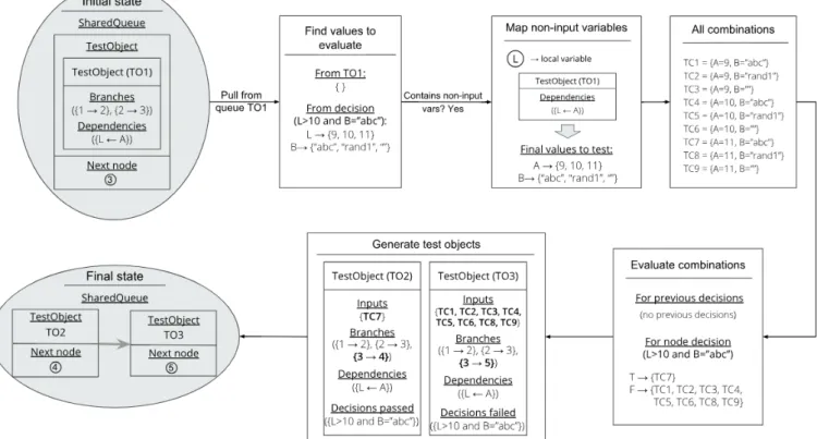
4.1.2 The test object . . . 37
4.1.3 Data types and expressions . . . 38
4.1.4 Graph traversal . . . 40
4.1.5 Process nodes . . . 41
4.1.6 Coverage evaluation . . . 55
4.1.7 Expected output . . . 61
4.1.8 Warnings evaluation . . . 62
4.1.9 Test case prioritization . . . 64
4.1.10 Optimizations . . . 65
4.2 PoC with dummy model . . . 65
4.3 Tool applied to the OutSystems model . . . 68
5 Evaluation 71 5.1 Algorithm execution . . . 71 5.2 Usability experiment . . . 74 5.2.1 SUS . . . 74 5.2.2 Results analysis . . . 76 6 Conclusions 79 6.1 Contributions . . . 80 6.2 Future work . . . 80 Bibliography 83 A Detailed test results 93 A.1 Algorithm execution . . . 93
A.2 Usability experiment . . . 95
A.3 Graph and questions . . . 95
A.3.1 Graph A . . . 95
B Documents referenced 99
C..VL/HCC paper 107
I OS Language Overview 111
II Test Automation Tools 117
II.1 Tools . . . 117
II.1.1 Proprietary software tools . . . 117
L i s t o f F i g u r e s
2.1 Overview of the main components of the OutSystems platform and the
archi-tecture of the Platform Server [52]. . . 6
2.2 OutSystems platform overview [76]. . . 8
2.3 Example of a code trace from Service Studio. . . 8
2.4 Different testing levels [9]. . . 13
2.5 Subsumption relations among control flow coverage criteria [5]. . . 20
2.6 Subsumption relations among coverage criteria regarding uses and defs [85]. 22 2.7 BFS execution example. . . 25
2.8 DFS execution example. . . 26
4.1 Example of a graph procedure in OutSystems to be traversed over the course of this chapter. . . 36
4.2 Structure of the developed algorithm.. . . 37
4.3 OutSystems language nodes representing the different variable types. . . 38
4.4 Graph traversal shows a depth-first behaviour from the standpoint of each singular thread. . . 40
4.5 Graph traversal shows a breadth-first behaviour from the standpoint of the entire algorithm where the different colours represent multiple threads. . . . 41
4.6 Traversal starts processing theStart node. . . . 42
4.7 Processing anAssign node. . . . 44
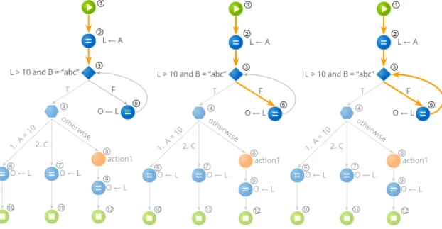
4.8 Processing anIf node.. . . 47
4.9 Graph after processing theIf node. . . . 48
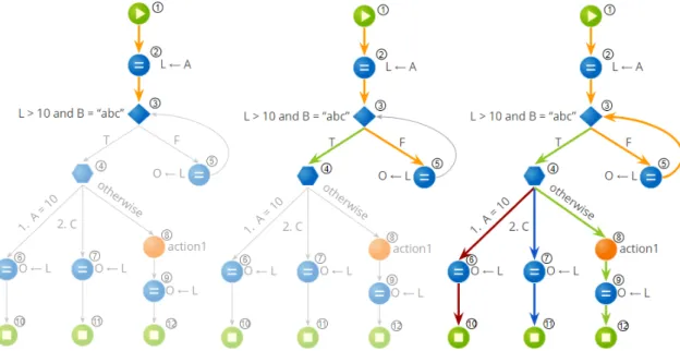
4.10 Processing aSwitch node.. . . 51
4.11 Graph after processing theSwitch node. . . . 51
4.12 Graph after processing the node of identifier 5. . . 52
4.13 Processing aUnsupported node. . . . 53
4.14 The graph and algorithm’s state after traversal of node with identifier 7. . . . 53
4.15 The graph and algorithm’s state after traversal of node with identifier 9. . . . 54
4.16 The graph and algorithm’s state while processing the last couple nodes and after the end of traversal of this graph. . . 55
4.18 Graph characteristics: set of all nodes, branches, simple conditions and
deci-sions found in the graph. . . 56
4.19 Nodes covered by each of the test objects generated by this algorithm. . . 57
4.20 Branches covered by each of the test objects generated by this algorithm. . . 58
4.21 Test cases per condition. . . 59
4.22 Truth tables for each decision, showing if there is a test object that is able to vouch for said entry.. . . 60
4.23 Test cases per decision. . . 60
4.24 Dead code and paths covered by each test object. . . 63
4.25 The order by which the code is covered if test cases from each path are executed sequentially from left to right. . . 66
4.26 XML file snippet from the graph being used as example. . . 66
4.27 Structure of this PoC. . . 67
4.28 Proof of concept (PoC) interface screenshot. . . 68
4.29 Structure of the tool implemented for ServiceStudio. . . 69
4.30 Screenshot of ServiceStudio where the command to call the tool can be seen. 69 4.31 Tool window with results from this example. a) shows the initial state of the window and b) after expanding all fields. . . 70
5.1 Scatter plot comparing the amount of top test cases presented against the total test cases generated by this tool. . . 72
5.2 Percentage represented by the top test cases over the total amount of test cases generated. . . 73
5.3 Scatter plot comparing the amount of total test cases generated for this tool against what would be generated if not for cause-effect graphing. . . 73
5.4 Percentage of correct answers for both methods. . . 75
5.5 SUS distribution. . . 77
A.1 Top test cases results. . . 93
A.2 Total test cases generated. . . 94
A.3 Total test cases generated without cause-effect graphing. . . 94
A.4 Graph A. . . 96
A.5 Graph B. . . 97
I.1 Processes tab in Service Studio. . . 111
I.2 Interface tab in Service Studio. . . 112
I.3 Logic tab in Service Studio. . . 113
L i s t o f Ta b l e s
2.1 List of nodes to be analysed for the test case generation with a simple
descrip-tion and the number of incoming and outgoing nodes. . . 9
2.2 Overview of all coverage criteria defined in this chapter. . . 23
3.1 Quick overview of the work presented in this chapter. . . 34
4.1 Expected values for the output variable. . . 62
4.2 Values used to identify the test object who covers more code and will be the first presented to the developer. . . 65
4.3 Results from the next step of prioritization. . . 65
5.1 Risk evaluation according to cyclomatic complexity [41].. . . 72
5.2 For each question on the usability tests, the correct answer rate for both the original method (manual analysis) and for the tool. . . 75
5.3 SUS meaning [7, 13]. . . 76
5.4 Mean SUS answer for each question. . . 76
5.5 SUS descriptive statistics.. . . 76
A.1 Detailed results obtained for each tested graph. . . 95
B.1 List of documents utilized in the making of this report. . . 99
II.1 List of proprietary software test automation tools [92]. . . 117
L i s t i n g s
1 Breadth-First algorithm [98] . . . 24
2 Depth-First algorithm [98] . . . 26
3 Process data types . . . 39
5 ProcessStart node . . . 42
6 ProcessAssign . . . 43
8 Auxiliary functions . . . 46
9 ProcessSwitch . . . 49
10 ProcessUnsupported . . . 52
Ac r o n y m s
BDD Behavior-driven development. BFS Breadth-first search.
BPT Business Process Technology.
DFS Depth-first search.
FAQ Frequently Asked Questions.
JAXB Java Architecture for XML Binding. JSON JavaScript Object Notation.
JSP JavaServer Pages.
OCL Object Constrained Language.
PoC Proof of concept.
SDG Sequence Diagram Graph. SUS System Usability Scale.
TDD Test-driven development.
TPLs Textual Programming Languages.
UI User Interface.
UML Unified Modeling Language.
VL/HCC IEEE Symposium on Visual Languages and Human-Centric Computing. VPLs Visual Programming Languages.
C
h
a
p
t
e
r
1
I n t r o d u c t i o n
This chapter will focus on introducing this thesis, starting with a description and con-textualization of the problem along with its motivations, followed by the objectives and contributions. Lastly, the chapter concludes with an overview regarding the structure of the remaining document.
1.1
Context and description
Software testing is a main process of software development. It is a quality control activity performed during the entire software development life-cycle and also during software maintenance [92]. Two testing approaches that can be taken are manual or automated.
In manual testing, the activities are executed by a human sitting in front of a computer carefully going through the application, trying various usage and input combinations, comparing the results to what the expected behaviour should be, reporting defects. Man-ual tests are repeated often during development cycles for source code changes and other situations like multiple operating environments and hardware configurations [92].
According to Dustin et al. [24] the definition for software test automation refers to the automation of software testing activities including the development and execution of test scripts, validation of testing requirements, and the use of automated testing tools. One clear beneficial aspect of automation is its ability to run more tests with less time when compared to manual testing, which increases productivity.
In this context, there are already a number of tools that allow automated testing over
Textual Programming Languages (TPLs)(a list of some of those tools can be consulted in
Annex II), but the same variety does not apply toVisual Programming Languages (VPLs).
VPLsrefer to any programming language that lets users create programs by manipu-lating the program elements graphically rather than by specifying them in a text editor
of source code [48]. With advantages including making programming more accessible, in particular, to reduce the difficulties that beginners face when they start programming, pureVPLsalso come with their own set of struggles, particularly when problems demand more flexibility than visual programming could offer.
With this in mind, tools such as OutSystems use a pragmatic mix of both visual and text-based programming, allowing developers to create software visually by drawing interaction flows, UIs and the relationships between objects, but also supplementing it with hand-written code where that’s the best thing to do. This model is well suited to the needs of modern software development. Low-code tools reduce the complexity of software development bringing us to a world where a single developer can create rich and complex systems in an agile1way, without the need to learn all the underlying technologies [88].
When confronted with the task of testing, the users developing in OutSystems have access to some tools that automate the process of test case execution but, in order to expedite the testing process, there is still a need for a tool that automizes the generation of the test cases themselves.
1.2
Motivation
A program is tested in order to add some value to it. This value comes in the form of quality and reliability, meaning that errors can be found and afterwards removed. This way, a program is tested, not only to show its behaviour but also to pinpoint and find as many errors as possible. Thus, there should be an initial assumption that the program contains errors and then test it [61].
Therefore, a valid definition for testing is [61]:
Testing is the process of executing a program with the intent of finding bugs.
As humans, we tend to be goal-oriented, so properly defining our goals has a major psychological effect [61]. If our goal is to prove that a program has no errors, we will steer subconsciously toward this goal, selecting test data that, will probably never cause the program to fail. On the other hand, if our goal is to show that a program is defective, our test data will have a higher probability in successfully finding errors. The latter approach will add more value to the program than the former [61].
A test case that finds a new bug can hardly be considered unsuccessful; rather, it has proven to be a valuable investment. An unsuccessful test case is one that causes a program to produce the correct result without finding any errors [61].
1Agile is a methodology that anticipates the need for flexibility and applies a level of pragmatism to
the delivery of the finished product. The OutSystems Agile Methodology addresses the need for speed and continuous change, delivering applications that truly respond to business needs [81].
Almost two decades ago, Weyuker et al. [105] pointed out that the most skilled soft-ware testers used to change jobs within their companies because a career in softsoft-ware testing was not considered advantageous enough for most professionals, raising the ques-tion of “how demotivated has a software tester to be to abandon their career and follow another path in software development process?”.
A recent survey [90] concerning work-related factors that influence the motivation of software testers shows that they are strongly motivated by a variety of work, creative tasks, recognition for their work and activities that allow them to acquire new knowledge.
Nowadays, there is a high need for quick-paced delivery of features and software to customers, so automating tests is of the utmost importance. One of its several advantages is that it releases the software testers of the tedious task of repeating the same assignment over and over again, freeing up testers to other activities and allowing for a variety in the work as well as opening space for creativity, being these some of the factors concluded in [90] said to improve software testers motivation at work.
As OutSystems aims at rapid application development, the automation of the test case generation activity, based on their applicational model, along with coverage evaluation, will be of great value to developers using OutSystems.
1.3
Objectives
The main objective of this work was to ideate and develop an algorithm to allow the gen-eration of test scripts in an automated manner over the low-code OutSystems language, not including the actual execution of said tests. This language is defined as being a visual programming language, with some accents of textual language whenever that is the best approach, in order to have the conveniences ofVPLs, but still be a functional and scalable language.
Another goal was to provide the ability to evaluate the coverage that the proposed solution can provide the code, according to several coverage criteria that will be detailed in the following chapters.
Finally, the viability of implementing this tool on top of the OutSystems main plat-form, the Service Studio, was analysed, evaluating the solution in terms of performance as the code grows in complexity since this will be the primary challenge as the test cases are expected to grow exponentially.
1.4
Key contributions
At the end of this thesis, there is a running tool, related to a sub-set of the OutSystems applicational model, able to automatically generate the test scripts for the selected code, and this tool is running on top of the OutSystems’ development environment. This work lays the foundation to have test coverage on applications made in OutSystems.
This feature will bring value to people developing applications in OutSystems, both internally, within the company, and also externally, to customers.
Complementing this tool, its implementation is documented in a published paper [15] (see Appendix B) for the IEEE Symposium on Visual Languages and Human-Centric Computing (VL/HCC)of 2018.
Outside of OutSystems, it is also expected that this work will contribute to further advance the state of the art of automated testing techniques, namely overVPLs.
1.5
Structure
The remainder of this thesis is organized as follows:
• Chapter 2-Background: here the focus is on the research that was performed, being the main topics the OutSystems platform, testing, automated testing, coverage criteria over graphs and graph traversal algorithms;
• Chapter 3 -Related work: this chapter presents some tools and techniques that relate to the context of this thesis, in this case, focused on the automatic generation of tests;
• Chapter 4-Implementation: depicts the algorithm conceptualized as well as details the implementation of both thePoCand the tool applied to the OutSystems model; • Chapter 5 - Evaluation: presents the results obtained for this work, both by the
execution of the tool as well as from usability tests performed;
• Chapter 6-Conclusions: concludes this dissertation with a quick overview of the work produced as well as identifies what can be the future of the tool hereby pre-sented;
• Appendix A - Detailed test results: further details the results recorded and the structure of the usability tests performed;
• Appendix B -Documents referenced: this appendix depicts all documents refer-enced throughout the present report, informing the main topics it approaches and the chapters it is referenced on;
• Appendix C - VL/HCC paper: shows the paper submitted and accepted for the
VL/HCCconference of 2018 focused on the work produced by this dissertation; • Annex I-Test Automation Tools: contains a high-level overview of the OutSystems
language;
• Annex II-Test Automation Tools: here are listed some tools that already exist for test automation, both open-source and proprietary.
C
h
a
p
t
e
r
2
Ba c k g r o u n d
This chapter provides background context related to this dissertation, covering: the Out-Systems platform, software testing overview (both manual and automated), coverage criteria applicable over graphs, graph theory and finally, graph traversal algorithms.
2.1
OutSystems
OutSystems is a software company whose primary focus relies on improving the produc-tivity and simplifying the day-to-day life of IT professionals. The OutSystems platform was developed with a strong focus on performance, scalability, and high-availability and can be used to create web and mobile applications. The OutSystems language allows users to develop at a higher abstraction level, without the need to worry over low-level details related to creating and publishing applications [52,82].
2.1.1 OutSystems platform
Figure 2.1depicts the main components of the OutSystems platform and the architec-ture of the Platform Server where the components of the typical 4-tier web application architecture are represented in white, which the OutSystems platform complements with an extra set of services and repositories displayed in red. Service Studio and Integration Studio, the two products which compose OutSystems Development Environment, are desktop tools that interact with the Platform Server via Web services [52].
2.1.1.1 Service Studio
Service Studio is an environment where business developers assemble and change web and mobile business applications using visual models with a drag-and-drop paradigm.
Figure 2.1: Overview of the main components of the OutSystems platform and the archi-tecture of the Platform Server [52].
This tool also enables the modeling of UIs, Business Processes, Business Logic, Databases, Integration Components, SAP BAPIs [91], SOAP and REST Web Services, Security Rules, and Scheduling activities. Service Studio embeds a full-reference checking and self-healing engine that assures error-free, robust change across all application components.
When the developer publishes an application, Service Studio saves a document with the application model and sends it to the Platform Server [52].
2.1.1.2 Integration Studio
In Integration Studio, developers can create components to integrate existing third-party systems, microservices, and databases, or even extend OutSystems with their own code.
After the deployment of these components, they will be available to reuse by all applications built with OutSystems. Developers use Visual Studio to code integration components and can take advantage of existing ASP.NET [58] libraries.
When publishing a component, the development environment compiles it with a standard ASP.NET [58] compiler. The generated DLLs are sent to the Platform Server [76].
2.1.1.3 Platform Server
The Platform Server components take care of all the steps required to generate, build, package, and deploy native ASP.NET [58] and Java web applications on top of a Microsoft
stack, Oracle WebLogic [67] or JBOSS [40], using a set of specialized services [76]:
• Code generator: takes the application modeled in the IDE and generates native
ASP.NET [58] code, allowing the generation of applications that are optimized for performance, are secure and run on top of standard technologies;
• Deployment services: these services deploy the generated ASP.NET [58] application to
a standard web application server, ensuring an application is consistently installed on each front-end of the server farm;
• Application services: manage the execution of scheduled batch jobs, providing
asyn-chronous logging services to store events like errors, audits performance metrics.
2.1.2 Language
As it has already been briefly mentioned in previous sections, the OutSystems language allows developers to experience the benefits ofVPLsbut also takes into account the fact thatVPLshave a set of disadvantages associated, and the most concerning are [97]:
• Extensibility: visual languages allow developers to do a limited set of things easily,
but the edge cases are too difficult or even impossible to achieve. Tools should give more power, instead of limiting the developers;
• Slow code: every developer who has faced performance problems knows how hard
they are to diagnose and overcome. Visual languages can be leaky abstractions, generating slow code which is impossible to optimize.
With all of this in mind, the OutSystems language uses a pragmatic mix of both visual and text-based programming, supplementing the visual with text-written code where that is the best thing to do.
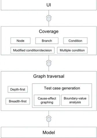
Figure 2.2 shows a visual representation of the OutSystems platform, where from Service Studio (2.1.1.1), the code created passes on to a Code Generator encapsulated in a file. This contains all the graph information and the application logic. This code containing elements which constitute OutSystems’ model, is the input to the algorithm meant to be developed during the course of this thesis.
The model for Service Studio comprises of a multitude of components that include a set of UI elements (widgets - text, container, link, etc), processes (Business Process Technology (BPT)- activities, timers, etc), amongst others (themes, entities, etc). Annex I
contains a high-level overview of the OutSystems language.
For the course of this work, only the application logic behind client/server actions and events will be considered.
Figure 2.2: OutSystems platform overview [76].
2.1.2.1 Nodes
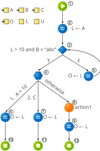
Figure 2.3 shows a logic flow in the OutSystems language, illustrated by a set of nodes that come together to form a graph representing a given method, function, procedure, etc. These nodes represent blocks of code that the developer can add to the graph as desired.
Considering the extension and complexity of the model provided by OutSystems, only a subset of the existing nodes will be evaluated in this thesis, as the time allocated for this work would not suffice. Table 2.1displays a list of the most pertinent information regarding the selected node types: visual representation, behavior description and num-ber of incoming and outgoing branches. Although incomplete, this list comprises a very interesting set of elements which are the most important for exercising decision flows, a starting point for future work.
Table 2.1: List of nodes to be analysed for the test case generation with a simple descrip-tion and the number of incoming and outgoing nodes.
Description In : Out
If
...
...
This node presents the typical behaviour of an if code block, with his Boolean condition and the outgoing flows accord-ing to the condition result, weather it is True or False. Contrary to some programming languages where the False branch can be omitted, in OutSystems, both branches are defined. ... ... ... ...1:2 Switch ... ...
This switch block analysis each decision and the flow will continue through the decision it verifies as true.
... ...1:N
Assign
... This block assigns a value (or object) to a variable. Each... assign node can comprise of multiple assignments
... ...1:1 Serv erA ction ...
This block represents the collapse of another graph that will contain code corresponding to an action to be executed on the server-side of the application.
2.1.3 Application testing
Due to the nature of visual development and continuous integrity validation built into OutSystems1, users do not need to worry about the underlying technical challenges, given the abstractions that OutSystems provides, which makes it less error prone [79].
Regardless, testing is a fundamental part of any software. OutSystems’ approach is to keep their platform open so it is compatible with the tools developers typically use. This way, testing is integrated in the continuous delivery cycle so there are not losses in productivity [71].
There are some tools available that allow the execution of tests for applications created in OutSystems. Something that is still missing, is a tool that can generate the test cases themselves, offering a coverage analysis and this, what the present dissertation proposes. 2.1.3.1 Unit Testing Framework
The Unit Testing Framework [84] provides a complete framework for implementing, executing and managing unit tests.
Teams find this approach particularly effective for calculation engines and business service components. Having a good set of unit tests for a system can help greatly when it is time to change or refactor a system [79].
2.1.3.2 Behavior Driven Development Framework
Test-driven development (TDD)is an evolutionary approach that requires the writing of automated tests prior to developing functional code in small, rapid iterations [47].
Behavior-driven development (BDD)was originally developed by North [63] in re-sponse to issues in TDD. It is focused on defining fine-grained specifications of the behaviour of the targeting system, in a way that they can be automated, allowing devel-opers to focus the creation of tests for the most critical use cases [79]. The aim goal of
BDDis to get executable specifications of a system [63,99].
TheBDDFramework [83] is an open source component the developer can adapt to its own needs, but already provides: creation of test scenarios and steps conformant toBDD
principles; support for multiple tests in the same page and the final statistics (number of successful/failed tests); amongst other features.
2.1.3.3 Functional, UI and Regression Testing
For functional and regression testing in web applications, OutSystems recommends the use of Selenium [95], but any strategy currently used to test traditional web applications apply as well.
1Continuous Integration is a software development practice where work is integrated frequently. Each
integration is verified by an automated build to detect integration errors as quickly as possible [32]. For this, OutSystems employed a validation engine - TrueChange [78] -, that assures robust and error-free changes across all applications and their modules.
Additionally, there is Test Automator [101], a browser (Selenium-based) and unit (WebService-based) regression testing tool that helps guarantee the quality of solution development by automating the execution of tests over the application.
2.2
Testing overview
Developing a large software system is an extremely complex and error-prone process. A fault might occur at any stage of development and it must be identified and treated as early as possible in order to stop its propagation. Quality engineers must be involved in the development process since the very early stages up beyond the product deployment all the way through maintenance and post-mortem analysis [8].
Testing plays an important role in achieving and assessing the quality of a software product. On the one hand, we are able to improve the quality of the products as we continuously test, find a defect and fix it, all during development. On the other hand, we also assess how good our system is when we perform system-level tests before releasing a product [50].
2.2.1 Testing techniques
The term testing refers to a full range of test techniques, even quite different from one another, and embraces a variety of aims [9].
2.2.1.1 Static techniques
The distinction between static and dynamic techniques depends on whether the software is executed or not. Static techniques are based solely on the (manual or automated) examination of project documentation, of software models and code, and other related information about requirements and design. Thus static techniques can be employed all along development, and their earlier usage is, of course, highly desirable.
Traditional static techniques include [9]:
• Software inspection: a very popular software inspection process was created by
Michael Fagan and is referred to as the Fagan inspection. It is a structured process of trying to find defects in development documents such as programming code, spec-ifications, designs, and others during various phases of the software development process. Fagan Inspection defines a process as a certain activity with a pre-specified entry and exit criteria and then, inspections can be used to validate if the output of the process complies with the exit criteria specified for the process [28,29];
• Algorithm analysis and tracing: the process in which the complexity of algorithms
employed and the worst-case, average-case and probabilistic analysis evaluations can be derived.
2.2.1.2 Dynamic techniques
Dynamic techniques obtain information about a program by observing executions. In contrast to static analysis, which examines a program’s text to derive properties that hold for all executions, dynamic analysis derives properties that hold for one or more executions by examining the running program. While dynamic analysis cannot prove that a program satisfies a property, it can detect violations of properties and also provide useful information to programmers about the behavior of their programs [6,9].
2.2.2 Testing activities
In order to test a program, one must perform a sequence of testing activities, namely [50]:
1. Identify an objective to be tested: this will define the intention, or purpose, of the
de-signing of the test cases to ensure said objective is successfully met by the software;
2. Select inputs: the selection of test inputs can be based on the requirements
specifi-cation of the software, the source code or our expectations. Test inputs are selected by keeping the test objective in mind;
3. Compute expected outcome: without running the program, one must already have an
understanding of what the expected outcome should be, and that can be done from an overall, high-level understanding of the test objective and the specification of the program under test;
4. Execute the program: we must setup the execution environment accordingly and
execute the program with the selected inputs, observing the actual outputs;
5. Analyse the test result: finally, having executed the test, the last testing activity is
to analyse the result, comparing the actual outcome with the expected one and assigning a verdict to the program.
2.2.3 Testing levels
Testing can be performed at different levels involving the complete system, or only parts of it, throughout its lifecycle. A software system goes through several stages of testing before it is actually deployed [9], some of which are characterized next:
1. Unit level: here, individual program units, such as procedures, functions, methods
or classes are tested, in isolation;
2. Integration level: in general terms, integration is the activity of aggregating software
pieces to create a larger component. Integration testing aims at testing these larger components to guarantee that the pieces that were tested in isolation can now work together as a whole;
3. System level: this level includes a wide spectrum of testing, being a critical phase in
a software development process because of the need to meet a tight schedule close to the delivery date, to discover most faults and to verify that fixes are working and have not resulted in new faults;
4. Acceptance level: after the completion of the system-level testing, the product is
delivered to the customers that perform their own series of tests, based on their expectations for the system. The objective of acceptance testing is to measure the quality of the product, rather than searching for the defects, which is the objective of system-testing.
The first three levels of testing are performed by a number of different stakeholders in the development organization, whereas acceptance testing is usually performed by the customers.
There is a type of testing that is usually performed throughout the lifecycle of a system, whenever a component of the system is modified, called regression testing. The main idea is to ensure that the modification did not introduce any new faults in the portion that was not subject to modification.
Figure 2.4: Different testing levels [9].
2.2.4 Test design techniques
Three broad concepts in testing, based on the sources of information for test design, are white-box, black-box, and grey-box testing [25].
2.2.4.1 White-box
In white-box or structural testing, the source code for the system is available to the tester and the test cases are selected based on the implementation of the software. The objective here is to execute specific parts of the software, such as specific statements, branches or paths. The expected results are evaluated under a set of coverage criteria, just as the ones depicted insection 2.4.
2.2.4.2 Black-box
In black-box or functional testing, the tester does not have access to the internal details of the software that is thus treated as a black box. The test bases are selected based on the requirements or design specification of the system under test. Functional testing emphasis relies on the external behavior of the software.
Commonly used black-box methodologies are detailed next.
Equivalence Partitioning .
Equivalence partitioning is a technique in which the input domain of a problem is divided
into a finite number ofequivalence classes such that it can be reasonably assumed that a
test derived from a value of each class is equivalent to a test derived from any other value from the same class.
This technique aims at defining test cases that uncover classes of errors, thereby re-ducing the total number of test cases that must be developed, as some of them would prove to be redundant [25,61].
Boundary-value analysis .
Boundary-value analysis focuses more on testing on boundaries, or where they are chosen. It includes minimum, maximum, just inside/outside boundaries, error values, and typical values [25]. It differs from equivalence partitioning in two aspects [61]:
1. Instead of selecting any element in an equivalence class as being representative, boundary-value analysis requires that one or more elements be selected such that each edge of the equivalence class is the subject of a test;
2. Instead of just focusing on the input conditions, test cases are also derived by con-sidering the result space (output equivalence classes).
Cause-effect graphing .
In this technique, testing starts by creating a graph and establishing the relationship between effects and its causes. Identity, negation, logic OR and logic AND are the four basic symbols which express the interdependency between cause and effect [25].
Cause-effect graphing has a beneficial side effect in pointing out incompleteness and ambiguities in the specification.
Error guessing .
The basic idea behinderror guessing consists in writing test cases based on possible or
error-prone situations. These can be identified both by intuition and experience and in-clude classic cases as the number 0 as input or “none” and “one” when a variable number of inputs or outputs can be present. Another idea is to identify test cases associated with assumptions that the programmer might have made when reading the specification [61].
2.2.4.3 Grey-box
Grey-box testing can be derived from the previous two and is a technique to test the application with limited knowledge of the internal working of an application and also has the knowledge of fundamental aspects of the system.
Commonly employed grey-box methodologies are depicted next.
Matrix Testing .
This testing technique starts by defining all the variables that exist in the software. Each variable will have an inherent technical and business risk associated and can be used with different frequency during its’ lifecycle. All this information is summarized in tables from which then the design of test cases is derived [25].
Regression Testing .
In this technique, if there are new changes made to the software, there is a selection of already executed test cases that are then re-executed in order to check if the change in the previous version has regressed other aspects of the program in the new version [25]. This technique is done to make sure that new code changes do not have undesired side effects over already existing functionalities.
2.2.5 Manual and automatic testing
Testing work can be roughly divided into automatic and manual testing, as follows [34]:
• Manual testing: a human tester takes the role of an end user and executes the features
of a given software under test to ensure its behaviour is as expected;
• Automatic testing: the use of special software to control the execution of tests and
the comparison of actual outcomes with predicted outcomes.
2.3
Test automation
It is unproductive to test software manually, since the thousands of scenarios human testers generate are vulnerable to inaccurate results, and manual tests are also slow and difficult to repeat. In addition, a manual approach might not be the most effective in finding certain defects. Therefore, test automation aims to have the actions that enhance the quality of the product done constantly in an effort to make the software as error-free as possible by the time it goes out on the market.
These actions may include: development of test cases; selection of inputs and compu-tation of outputs; evaluations after the scenarios are run, among others. Thanks to test automation, total product quality and efficiency can be greatly increased in the major software development processes, with versions delivered much faster, less staff assigned for manual testing and fewer software errors [27].
But, although we may see test automation as a solution to decrease testing costs and to reduce cycle time in software development, if it is not applied at the right time and context with the appropriate approach, it might fail [34].
In test automation, we have four basic components: testers, (test automation) tools, test cases, and the system under test. Test engineers interact with the test automation tools and develop test cases which are then executed using the chosen test automation tool. The tests exercise the system under test and the tool provides test reports for humans to interpret. Even though the introduction of test automation often increases the cost of creating tests, the cost of re-running them decreases [42].
Test automation provides us with a great amount of advantages [22,92]:
• Saves time and money: tests have to be repeated during development cycles to ensure
software quality and so every time source code is modified, such tests must be re-peated to ensure no bugs were accidentally introduced into the code. Repeating the tests manually is costly and time-consuming, as testers could be focused on other tasks such as dealing with more complex features. After their creation, automated tests can be run multiple times with decreased cost and at a much faster pace com-pared to manual tests as it can reduce the time to run said tests from days to hours, and saving time translates directly into saving money;
• Improves consistency of test results: even the most expert tester will make mistakes
during monotonous manual testing. Automated tests perform the same steps pre-cisely every time they are executed and never forget to record detailed results;
• Provides the ability to perform tests that are very difficult to execute manually thus
increasing test coverage: automated software testing tools can look inside an
appli-cation and see memory contents, data tables, file contents, and internal program states to determine if the product is behaving as expected, easily executing thou-sands of different complex test cases during every test run providing coverage that is impossible with manual tests. These tools can also simulate tens, hundreds or even thousands of virtual users interacting with the network, software and web applications, something that was also extremely difficult to do with manual testing;
• Team morale improves: as there is no more need to spend time executing repetitive
tasks, automated software testing gives teams time to spend on more challenging and rewarding projects, allowing team members to improve their skill sets and confidence and, in turn, they pass those gains on to their organization.
There are also some risks/difficulties associated with the automation of software test-ing activities [22,92]:
• Tools cost and learning curve: testing automation lays heavily on top of the tools
that are used. A careful consideration needs to be made in whether to purchase a licence for a proprietary software tool, or adapting a pre-existing open source one
or even, developing a completely different type of tool. Along with this, learning how to manipulate the chosen tool also introduces an extra cost. A list with both proprietary and open source tools is available inAnnex II;
• Unrealistic expectations from the tool: having unrealistic expectations from the tool
is a risk that may lead to schedule and cost seepage;
• Maintenance of the automation scripts: maintaining the scripts may prove to be
ex-pensive. For a large project, the volume of test data might be high and it requires a good structure to maintain all the test data.
2.4
Coverage criteria
Software test coverage is a measure used to describe the degree to which the source code of a program is executed when a particular test suite runs. A program with high test coverage, measured as a percentage, has had more of its source code executed during testing which suggests it has a lower chance of containing undetected software bugs compared to a program with low test coverage.
In terms of coverage over graphs, it is usual to divide these criteria into two types:
control flow coverage criteria and data flow coverage criteria. Control flow criteria uses the
control structure of a program to develop the test cases. Data flow criteria are based on
the flow of data through the software artifact represented by the graph.
A general definition for graph coverage can be enunciated as follows: given a setTR
of test requirements for a graph criterionC, a test set T satisfies C on graph G if, and only
if, for every test requirementtr in TR, there is at least one test path p in path(T) such that p meets tr [5].
2.4.1 Control flow coverage
Control flow coverage, or structural coverage as it is also called in literature, refer to white-box methodologies and they include: node, branch and path coverage [5,50,104].
Node coverage .
Node coverage - also referred to statement or segment coverage -, refers to executing individual program statements and observing the outcome. We say we have 100% node coverage if all the statements have been executed at least once in all of our test cases combined. Complete node coverage is the weakest coverage criterion in program testing.
Before moving on to the next few coverage criteria, it might be useful to define and distinguish the concepts of condition and decision:
• Condition is a simple Boolean expression, meaning that it cannot be broken down into simpler Boolean expressions. For example, the following expressions are con-ditions:
1: A == B
2: C
• Decision is a Boolean expression composed of conditions and zero or more Boolean operators. A decision without a Boolean operator is a condition. For example, the following expressions are decisions:
1: A && B
2: (A && B) || C
Decision Coverage .
A decision - also known as edge or branch - is an outgoing edge from a node. Having full decision coverage means selecting a number of paths such that every decision is included in at least one path.
Condition coverage .
Full condition coverage states that each possible outcome of each condition occurs at least in one test case, meaning that all conditions are, at least one time, true and false.
Modified condition-decision coverage .
After the introduction of decision and condition coverage, modified condition-decision coverage refers that every condition in a decision that has been shown to independently affect that decision’s outcome must be tested by varying just that condition while holding fixed all other possible conditions.
Multiple condition coverage .
In multiple condition coverage, or conditional combination coverage, all possible combi-nations of conditions should be evaluated.
Multiple condition coverage implies branch, condition, condition-decision and modi-fied condition-decision coverage, which will have an exponential blow-up (2number_of _conditions) and some combinations may be infeasible.
Path Coverage .
Here, all possible paths in the graph are taken into account. However, a program may contain a large or even infinite number of paths. A very common example is when we have cycles within the graph, where complete path coverage is not feasible since each cycle iteration will originate a new path.
In order to try to get as close as possible to complete path coverage, there are also other path coverage criteria based definitions. The most common include [5]:
• Prime Path Coverage.
Before defining what a prime path is, there is a need to introduce the definition of a simple path.
A path from ni to nj is said to be simple if no node appears more than once in the path, with the exception of the first and last nodes that may be identical. This means that simple paths have no internal loops, although the entire path itself may be a loop. These paths are very useful given that any path can be created by composing simple paths.
Even small programs may have a very large number of simple paths. For a simple path coverage criterion we would like to avoid enumerating the entire set of simple paths and, instead, list only the maximal length simple paths, to which we call a prime path [5].
A path from nito njis called a prime path if it is a simple path and does not appear
as a proper sub-path of any other simple path.
Therefore, the prime path coverage criterion is defined as having all prime paths show up in at least one test case. This way, we can say we have reached 100% prime path coverage.
– Simple Round Trip Coverage.
A round trip path is a prime path of nonzero length that starts and ends at the same node. In simple round trip coverage, it is required that the test cases contain, at least, one round-trip path for each reachable node in the graph that begins and ends a round-trip path [5].
– Complete Round Trip Coverage.
In complete round trip coverage, it is required that all round-trip paths for each reachable node in the graph are tested.
• Specified Path Coverage.
In specified path coverage, instead of requiring all paths, it is only considered a specified set of paths. For example, these paths might be given by a customer in the form of usage scenarios.
Figure 2.5 presents the subsumption relations between the control flow coverage criteria previously introduced, i.e., indicates which criteria are assumed to be covered once other criterion is reached. For example, when decision coverage is reached, it is implied that node coverage is also covered, and so on.
2.4.2 Data flow coverage
Data flow analysis focuses on how variables are bound to values, and how these variables are to be used. Just as one would not feel confident about a program without executing
Figure 2.5: Subsumption relations among control flow coverage criteria [5].
every statement in it as part of some test, one should not feel confident about a program without having seen the effect of using the value produced by each and every computation. Traversing all paths does not guarantee that all errors will be detected. We must be aware that path selection criteria cannot ensure that a set of test data capable of uncovering all errors will be chosen, as it was demonstrated in [85,86].
2.4.2.1 The Rapps and Weyuker Family of Criteria
Both Rapps and Weyuker have defined a family of coverage criteria based on definitions and uses of variables. The first reports of said criteria can be consulted in [85,86].
Their idea was that in order to test a software correctly, we should focus on the flows of data values and try to ensure that the values created at one point in the program are not only created but also used correctly. This is done by focusing ondefinitions and uses
of values. Adefinition (def ) is a location where a value for a variable is stored into memory.
Ause is a location where a variable’s value is accessed. These data flow testing criteria
use the fact that values are carried fromdefs to uses. These are called the du-pairs - also
known asdefinition-uses, def-use, and du associations and the idea is to exercise du-pairs
in various ways [5].
Each variable occurrence is classified as being a definitional, computation-use, or predicate-use occurrence. Those are referred to asdef, c-use and p-use, respectively. Since defs have already been defined, the definitions of both c and p-use are as follow:
• p-uses occurs when a variable is used to evaluate wheater a predicate is true or false;
• c-uses occurs when a variable is used to compute the value of other variables, or
output values.
• y = f (x1, ..., xn) ⇒c-use of variables x1, ..., xnanddef of y;
• read x1, ..., xn ⇒def of variables x1, ..., xn;
• print x1, ..., xn ⇒c-uses of variables x
1, ..., xn;
• if p(x1, ..., xn) then goto m ⇒ p-uses of variables x1, ..., xn.
An important concept when discussing data flow criteria is that a def of a variable
may or may not reach a particularuse. The most obvious reason would be because no
path goes from the definition to any use. But, a more subtle reason is that the variable’s value may be changed by anotherdef before it reaches the use. Thus, a path from li to ljis
said to bedef-clear with respect to variable v if no location between li and lj changes the
value [85]. .
Next, the definitions of All-Defs, All-P-Uses, All-C-Uses/Some-P-Uses, All-P-Uses/Some-C-Uses, All-Uses, and All-du-Paths Coverage will be introduced.
All-Defs Coverage .
This criterion is satisfied if, for every variable defined, there is a path included in at least one of our test cases, that goes from the definition to a use. In a more informal way, each
def reaches at least one use.
All-P-Uses Coverage .
Here, we need to have, in at least one of our test cases, a path from every variable defini-tion to the set of all itsp-uses.
All-C-Uses/Some-P-Uses Coverage .
To accomplish all-c-uses/some-p-uses coverage it is required that everyc-use of all
vari-ables defined must be included in some path of our test cases. If there is no suchc-use,
then some p-use of the definition of the variable must be included. Thus to fulfill this
criterion, every definition which is ever used must have someuse included in the paths
of the test cases, with thec-uses particularly emphasized.
All-P-Uses/Some-C-Uses Coverage .
Similar to the previous criteria, only here we put the emphasis on thep-uses, and therefore,
everyp-use of all variables defined must be included in some path of our test cases. If
there is nop-use, then some c-use must be included.
All-Uses Coverage .
All-uses criterion is satisfied if, for every definition of a variable, there is a path in our test cases that includes adef-clear path from the definition to all its uses, both c-uses and
p-uses. In a more informal manner, this one requires that each def reaches all its possible uses.
All-du-Paths Coverage .
This one requires that eachdef reaches all possible uses through all possible du-paths.
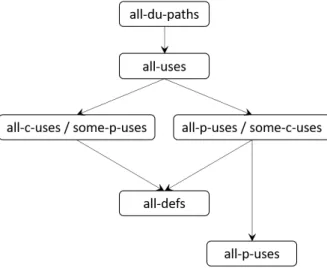
Figure 2.6shows the subsumption relations, this time, between the criteria introduced by Rapps and Weyuker.
Figure 2.6: Subsumption relations among coverage criteria regarding uses and defs [85].
2.4.2.2 Ntafos’ Required k-Tuples Criteria
Ntafos uses data flow information to overcome the shortcomings of using control flow information alone to select paths defining a class of path selection criteria, based on data flow analysis, the Required k-Tuples. These criteria require that a path set cover
chains of alternating definitions and uses, called k-dr interactions. A k-dr interaction propagates information along a sub-path that is called an interaction sub-path for the k-dr interaction [3,19].
2.4.2.3 Laski’s and Korel’s Criteria
Laski and Korel define criteria that emphasize the fact that a given node may contain uses of several different variables, and that each use may be reached by several definitions occurring at different nodes. These criteria are concerned with selecting sub-paths along which the various combinations of definitions reach the node and they are referred to as the Context Coverage and Ordered Context Coverage criterion [19].
2.4.3 Summary
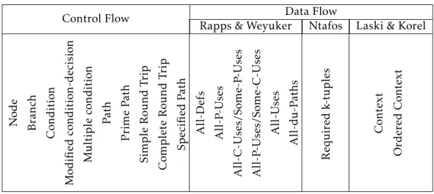
Table 2.2: Overview of all coverage criteria defined in this chapter.
Control Flow Data Flow
Rapps & Weyuker Ntafos Laski & Korel
Node Branch C ondition . Modified condition-decision . M ul tiple condition P ath Prime P ath Sim ple Round T rip C om plete Round T rip Specified P ath All-Defs All-P -Uses All-C-Uses/Some-P -Uses All-P -Uses/Some-C-Uses All-Uses All-d u-P aths Required k-tuples C on text Ordered C on text
2.5
Testing over graphs
This section starts with an introduction to graph theory, followed by some graph traversal algorithms.
2.5.1 Introduction to graph theory
As it was already covered insection 2.1, the OutSystems programming language is a visual language that represents the generated code visually through graphs, hence why we need a more in-depth understanding on how we can cover and traverse graphs.
A graph G=(V, E) is defined by a set of vertices V, and contains a set of edges E. Several fundamental properties of graphs impact the choice of data structures used to represent them and the algorithms available to analyse them. The first step in any graph problem is to classify the graphs that are being dealt with according to a set of properties, including [98]:
• Undirected vs Directed: a graph is said to be undirected if edge (x, y) ∈ E implies that
(y, x) ∈ E, that is, there is no direction imposed over the flow in the edges;
• Weighted vs Unweighted: each edge (or vertex) in a weighted graph is assigned a
nu-merical value, implying that said edge or vertex has a certain cost or gain associated with its traversal. In unweighted graphs there is no cost distinction between the various edges and vertices;
• Cyclic vs Acyclic: this property refers to the existence (or not) of cycles in the graph;
• Implicit vs Explicit: certain graphs are not explicitly constructed and then traversed,
but build as they are used. Because there is no need to store the entire graph, it is often easier to work with an implicit graph than explicitly construct it prior to analysis;
• Labeled vs Unlabeled: each vertex is assigned a unique name or identifier in a labeled
graph to distinguish it from all others. In unlabeled graphs, no such distinctions are made;
• Connected vs Disconnected: a graph is said to be connected if there is a path between
every pair of nodes. In a connected graph there are no unreachable nodes.
2.5.2 Graph traversal
There are two primary graph traversal algorithms:Breadth-first search (BFS)and Depth-first search (DFS). The breadth-first algorithm (2.5.2.1), along with the depth-first (2.5.2.2), are probably the most simplistic uninformed search procedures. For certain problems, it makes no difference which one is used, but in others the distinction is crucial. The differ-ence between these two algorithms lays in the order in which they explore vertices. This order depends completely upon the container data structure used to store thediscovered
vertices.
2.5.2.1 Breadth-First
Breadth-first’s traversal proceeds uniformly outward from the start node, exploring the neighbour nodes layer-wise, after which moving towards the next-level neighbour nodes [98].
One interesting guaranteeBFSprovides, is that when a goal node is found, the path expanded is of minimal length to the goal. A disadvantage of this solution is that it requires the generation and storage of a tree whose size is exponential in the depth of the shallowest goal node [62].
A pseudo-code for this algorithm can be seen in Algorithm 1. Algorithm 1Breadth-First algorithm [98]
1: procedure B F S ( G , s)
2: for eachvertex u ∈ V [G] − s do
3: state[u] = “undiscovered”
4: p[u] = nil, i.e. no parent is in the BFS tree
5: state[s] = “discovered”
6: p[s] = nil
7: Q = s
8: whileQ , ∅ do
9: u = dequeue[Q]
10: process vertex u as desired 11: for eachv ∈ Adj[u] do
12: process edge (u, v) as desired
13: ifstate[v] = “undiscovered” then
14: state[v] = “discovered”
15: p[v] = u
16: enqueue[Q, v]
Figure 2.7illustrates a run of theBFSalgorithm over a graph, with the insight of the associated data structures and it’s modification alongside the running of the algorithm.
An example applying theBFSalgorithm over a directed graph is shown inFigure 2.7.
Figure 2.7: BFS execution example.
TheUniform-cost search [23], proposed by Dijkstra, is a variant ofBFS in which all
the branches in the graph have an associated cost and nodes are expanded outward from the starting node along the “contours” of equal cost rather than along contours of equal depth. If the cost of all arcs in the graph are identical, then uniform-cost is the same as breadth-first search [62].
2.5.2.2 Depth-First
DFSis one of the most versatile sequential algorithm techniques known for solving graph problems. Tarjan [100] and Hopcroft and Tarjan [43] first developed depth-first algo-rithms for connected and biconected components of undirected graphs, and strong com-ponents of directed graphs.
DFSgenerates the successors of a node, just one at a time and, as soon as a successor is generated, one of its successors is generated and so on. To prevent the search process from running away toward nodes of unbounded depth from the start node, a depth bound can be set, making it so that no successor is generated whose depth is greater than the depth bound (it is presumed that not all nodes lie beyond the depth bound) [62].
This algorithm only requires part of the search tree consisting of the path currently being explored and traces at the yet fully expanded nodes along that path to be saved. The memory requirements are thus linear in depth bound. A disadvantage ofDFSis that when a goal is found, we are not guaranteed to have a minimal length path. Another
problem is that we may have to explore a large part of the search space even to find a shallow goal if it is the only goal and a descendant of a shallow node expanded late [62].
A valid pseudo-code for this algorithm can be seen inAlgorithm 2. Algorithm 2Depth-First algorithm [98]
1: procedure D F S ( G ,u )
2: state[u] =“discovered”
3: process vertex u if desired
4: for eachv ∈ Adj[u] do
5: process edge (u,v) if desired
6: ifstate[v] = “undiscovered” then
7: p[v] = u
8: DFS(G, v)
9: state[u] =“processed”
Figure 2.8illustrates a run ofDFSover a directed graph.
Figure 2.8: DFS execution example.
The computational complexity ofDFSwas investigated by John Reif [87] that consid-ered the complexity of computing the depth-first search, given a graph and a source. A decision version of the problem (testing whether some vertex u occurs before some vertex v in this order) is P-complete, meaning that it is“a nightmare for parallel processing”.
![Figure 2.1: Overview of the main components of the OutSystems platform and the archi- archi-tecture of the Platform Server [52].](https://thumb-eu.123doks.com/thumbv2/123dok_br/19178987.944417/30.892.127.775.146.569/figure-overview-components-outsystems-platform-tecture-platform-server.webp)
![Figure 2.2: OutSystems platform overview [76].](https://thumb-eu.123doks.com/thumbv2/123dok_br/19178987.944417/32.892.205.686.149.517/figure-outsystems-platform-overview.webp)
![Figure 2.5: Subsumption relations among control flow coverage criteria [5].](https://thumb-eu.123doks.com/thumbv2/123dok_br/19178987.944417/44.892.238.655.142.417/figure-subsumption-relations-among-control-flow-coverage-criteria.webp)