Effective Masses for Donor Binding Energies in Non-Magnetic and Magnetic
Quantum Well Systems: Effect of Magnetic Field
S. Rajashabala and K. Navaneethakrishnan
School of Physics, Madurai Kamaraj University, Madurai-625021, India
Received on 24 May, 2007
Donor binding energies in quantum well systems using position dependent effective masses are obtained. Results are provided for GaAs-Ga1−xAlxAs and the semimagnetic CdTe-Cd1−xMnxTe systems. In the latter the barrier height reduces in a magnetic field. Using the available experimental data the variations of the barrier height with magnetic field has been obtained using a simple model. Our results are in good agreement with similar works in the literature in the case of constant effective mass for the donor electron. However, in the case of the semi magnetic system and in the case of the position dependent effective mass, the results obtained are shown to be appreciably different for narrow well dimensions. The validity of the effective mass approximation in the case of applied magnetic field is also critically examined.
Keywords: Quantum wells
I. INTRODUCTION
The effective mass theory (EMT) [1] enunciated by Kohn and Luttinger is very useful in the study of impurity states in semiconductors. Apart from many valley semi conductors [2,3] such as Si, Ge, GaP etc. in almost all situations this theory is used in interpreting the rich electrical and optical data. This theory in its simplest form assumes a hydrogen like donor atom immersed in a dielectric background. The energy eigenvalues of such a system can be obtained using a potential V (r)=e/ε(r)r whereε(r)is the static dielectric screening function and r is the distance between the donor ion and electron. Since the static dielectric constant εand the effective mass m∗ at the bottom of conduction band are around 10 and 0.1m0respectively (m0is free electron mass) for a typical semiconductor, the impurity orbits are quite large,
∼100 ˚A. Hence the screening function may be replaced by a static dielectric constant in the potential energy term of the Hamiltonian. This theory rests on two basic approximations [1]:
1) Eiona/∆Ea∗ <<1 where Eion is donor ionization en-ergy, ∆E is the average separation between two bands, a the lattice constant, a∗ the effective Bohr radius defined as a∗=ε~2/m∗e2, and
2)|κ|/κBZ=a/6.2a∗<<1 where|κ|is approximately equal
to 1/a∗andκBZ is the wave vector of the radius of the
Bril-louin zone approximating the real BrilBril-louin zone of the sys-tem, which isp3
24π2/a3=6.2/a
Low dimensional semiconductor systems have attracted considerable attention in the last two decades. After the path-breaking work of Bastard [4], several researchers have con-tributed to the understanding of the optical and electronic properties of impurities in quantum well (QW) systems. This includes quantum well wires, quantum dots and superlattices. Several novel superlattice systems have been fabricated and rich interesting physics has come out of such studies [5,6]. In a QW system when the well dimension is much smaller than the donor effective Bohr radius, the EMT requires close scrutiny, since the potential varies rapidly at the barriers. In almost all studies so far the EMT has been used even for well
dimensions of the order of a mono layer or so(<10 ˚A). Inter-estingly, the quantum effects such as the quantum size effect manifest under strong confinement, which requires well di-mensions ranging from 10 ˚A to about 200 ˚A or so. Hence applications of the EMT to such confined systems require a critical analysis.
Several works have appeared testing the validity of the ef-fective mass approximation (EMA) in the past. Either they suggest reformulation or lead to more numerical procedures unsuitable for the interpretation of experimental data [7-9].
In the present work we have considered a donor electron in a QW subjected to an external magnetic field. The donor binding energies are calculated within the EMA by following a variational procedure. We have considered quantum wells (QWs) of the semimagnetic semiconductor system also. The variations of the barrier height with magnetic field are con-sidered using a simple model presented in [10]. The above calculations were repeated using position dependent effective mass (PDEM) as suggested in [11]. Finally the application of the EMT to the QW case is critically examined in section V.
The paper is organized as follows. In section II we present the theoretical framework. PDEM will be presented in sec-tion III and a brief discussion of semimagnetic semiconduc-tors will be given in section IV. We give our results and dis-cussion in section V. Main conclusions are summarized in sec-tion VI.
II. THEORETICAL FRAMEWORK
A. Infinite well model
The Hamiltonian for a donor impurity in the presence of a magnetic field applied along the z-direction in a square QW is given by
H=
µ
1 2m∗
¶ µ
P+eA
c
¶2 −e
2
εr+VW(z) (1)
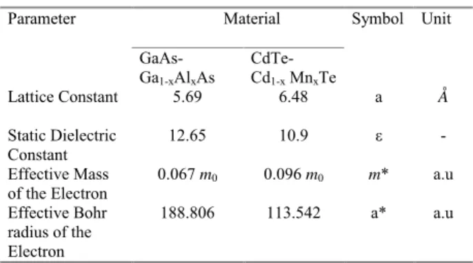
TABLE I: Material parameters for non -magnetic and magnetic quan-tum wells+
.
Material Parameter
GaAs-
Ga1-xAlxAs
CdTe-
Cd1-x MnxTe
Symbol Unit
Lattice Constant 5.69 6.48 a Å
Static Dielectric Constant
12.65 10.9 ! -
Effective Mass of the Electron
0.067 m0 0.096 m0 m* a.u
Effective Bohr radius of the Electron
188.806 113.542 a* a.u
+ Data from Ref. [10] & [11]
vector potential andεthe dielectric constant of the well mate-rial. The values of the material parameters for non -magnetic and magnetic QWs are given in Table 1.
The confining potential is given by
VW(z) = 0 |z| ≤
L 2
= ∞ |z|>L
2 (2)
HereLis the size of the QW.
After introducing the effective RydbergR∗=m∗e4/2~2ε2 as the unit of energy and effective Bohr radiusa∗=~2ε/m∗e2 as the unit of length, the above Hamiltonian takes the new form
H1=−∇2+γLz+
γ2ρ2
4 −
2 r+
VW(z)
R∗ (3)
Hereγ=~ω/2R∗is a dimensionless quantity. For GaAs, γ=1 corresponds to approximately 6 Tesla. The contribution of the second term vanishes for the ground state. We follow the variational procedure to obtain the ground state energy [12]. The ground state wave function of the above Hamiltonian can be written as
ψ1=N1e−αρ 2
e−βz2cos³πz L
´
|z| ≤L
2 (4)
whereαandβare variational parameters andN1is normal-ization constant. Yafet et al. used the product Gaussian with two parameters for bulk semiconductors [13]. This form was shown to be accurate forγ>1 Several subsequent works also employ the form given in Eq. (4) for QW systems with great success [14].
Minimizing<H1min> with respect toα andβ, the ion-ization energies for various magnetic fields can be calculated using the following formula
Eion=ESub+γ−<H1min> (5) ESubis the sub band energy in the presence of a magnetic field, which can be calculated when the impurity potential is absent in Eq.(3). Since the zero of energy fixed at the bottom of the well is shifted above by Landau energy ~ωc/2 (which is γ expressed inR∗)and the subband energy,Eionis obtained as in Eq. (5).
B. Finite well model
The confining potential is given by
VW(z) = 0 |z| ≤
L 2
= V |z|>L
2 (6)
HereV is the barrier height of the QW. GaAs-Ga1−xAlxAs
-being a non-magnetic material, the barrier height doesn’t vary with the applied magnetic field. CdTe-Cd1−xMnxTe being a
semimagnetic material, the barrier height varies with the ap-plied magnetic field. In any QW of a magnetic material, the barrier height decreases with applied magnetic field for one spin orientation [10].
The ground state wave function of the above Hamiltonian can be written as,
ψ2 = N2e−αρ 2
e−βz2cos(δz) |z| ≤ L
2
= N3e−αρ2e−βz2e−ξ|z| |z| ≥L
2 (7)
Here
δ=
r
2m∗E
~2 and ξ=
r
2m∗(V−E)
~2 (8)
where α and β are variational parameters; N2 and N3 are normalization constants. The ionization energies for various magnetic fields can be calculated using Eq. (5).
III. POSITION DEPENDENT EFFECTIVE MASSES
In the infinite barrier model, since tunneling is not allowed, we use
bound within aδ- function well, wherein there is no period-icity (in the z-direction), whereas asL→∞, the system is 3-dimensional (i.e. bulk) characterized by the conduction band effective massm∗. A choiceλ−1≤a∗looks reasonable.
When the Barrier height is finite, which is always true in all practical situations, in addition to the mass correction given by Eq. (9), another contribution becomes essential. Since the carrier can tunnel through the barrier, the barrier mass should also be considered. We suggest
1/m∗(z) =A(1−Bz2) (10) whereAis as given by the RHS of Eq. (9),B=∆/L2andLis the size of the well.∆is as given below.
The position dependent effective mass used in Ref [15, 16] is given by m∗1(z) =g(z)m∗1 =a+bz2 where g(z) =
1+0.4018z2/L2.
It is shown that the contribution by PDEM is less than 1meV.We point out two draw backs of this mass variation.
(1) Either in the infinite barrier model or in a realistic sit-uation when x is large like 0.4, the probability of finding an electron at the boundary of the well is zero. Hence the above variation does not represent this situation eventhough the au-thors of Ref [15, 16] use x=0.32.
(2) Unlike their claim in Ref [15] that the effective mass tends to the bulk value whenL→0 and asL→∞, we notice that in the limit L→0 the effective mass becomes infinity which is un physical. However in this limit for a finite barrier problem, due to tunneling the effective mass should be that of the barrier. To overcome these draw backs we have suggested the mass variation as in Eq. (10).
The derivation of position dependent effective mass [1/m(z)] of Eq. (10) is as given below. The effective mass of the electron in the well can be written as
1/m∗(z) =a+bz2 (11) Appling the boundary conditions
(i) when z=0, 1/m∗(0) becomes ‘a’ which is equal to 1/m∗wgiven by Eq. (9).
(ii) whenz=L,1/m∗(L)becomes 1/m∗w+ bL2.We know
that the mass atz=Lis 1/m∗b, which is the barrier mass that depends onx. The value ofb is 1/L2£
1/m∗b−1/mW∗¤
. The effective mass of GaAs in the barrier varies with composition asm∗b(x)= 0.067+0.0835xfor 0≤x≤0.4.
Eq.(11) is modified as
1 m∗(z) =
1 mW∗ −
z2 L2
µ 1
mW∗ − 1 m∗b
= 1
mW∗
·
1−z 2 L2
µ0.0835x
mW∗
¶¸
= 1
mW∗
·
1−∆z 2 L2
¸
(12)
where ∆=0.0835x/mw∗ππ1 for GaAs-Ga1−xAlxAs system.
In the present work we extend our earlier work [11] to the case of CdTe-Cd1−xMnxTe, which is a semimagnetic material.
The effective mass of CdTe in the barrier region varies with composition as,m∗b(x) =0.096+0.067xfor 0≤x≤0.7 for CdTe-Cd1−xMnxTe system.
Eq. (12) is valid with ∆=0.067x/m∗wππ 1 and we have chosenx=0.2 for both the systems.
After simplifying the expression for∆, we obtain∆= 0.2 and 0.123 for GaAs-Ga1−xAlxAs and CdTe-Cd1−xMnxTe QW
systems respectively. The present results of mass variation are compared with the one used in Ref [15, 16] as given in Fig. 1.
0.04 0.08 0.12 0.16 0.2
0 50 100 150 200
z variable(Å)
m
*(z
) (a.u)
our model for L=100 Å
Qi model and L=100Å
Our model andL=1000 Å
Qi model and L=1000 Å
FIG. 1: Variation of effective mass in the well region for two different models.
In the present work, our aim is to check whether the use of a PDEM affects the donor ionization energy or not. The effects of such a PDEM on the donor binding energies in the presence of an external perturbation such as a magnetic field, that is applied along the growth direction of QW, is discussed using perturbation method for infinite and finite barrier con-finements.
The perturbation for infinite QW is chosen as H1=−~
2 2
µ
1 m∗(L)−
1 m∗
w 
∇2
and for finite QW, H1=−~
2 2
µ 1
m∗(z)−
1 m∗
w 
∇2.
We replace
1 2
µ
1 m∗(z)
¶ ∇2 as 1 4 · 1 m∗(z)∇
2+∇2 1 m∗(z)
¸
.
The expressions for(1/m∗(L))and 1/m∗(z)are as given in Eqs. (9) and (10).
IV. SEMIMAGNETIC SEMICONDUCTORS
Diluted magnetic semiconductors are semiconductor com-pounds in which some cations are randomly substituted by magnetic ions. The most widely studied alloys are II-VI semi-conductors containing manganese, particularly Cd1−xMnxTe.
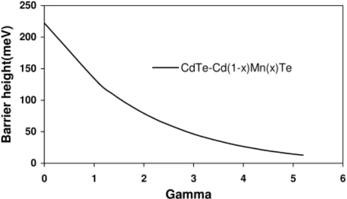
This (wide gap semiconductor) diluted magnetic quantum well system has received immense attention due to the in-teresting properties arising from the strong exchange inter-action between the magnetic ions and the carriers of con-duction and valence bands. One of the interesting prop-erties of the semi magnetic semiconductor is the barrier height decrease in a magnetic field. The variation of the band gap difference with magnetic field is given by [17] ¡
∆EgB/∆Eg0¢ =ηe−ξγ−1/η−1 where ∆EgB and ∆Eg0 are the band gap differences with and without magnetic field . The band gap of the material is given by [18] Eg(Cd1−xMnxTe)=1606+1587x(meV). Using the
experimen-tally available critical magnetic fields at which Type I to Type II superlattice transition occurs for acceptors, the results for the donors may be obtained by using the procedure as given in [10]. Fig. 2 shows the variation of barrier height with mag-netic field.
0 50 100 150 200 250
0 1 2 3 4 5 6
Gamma
Ba
rr
ie
r he
ight(me
V
)
CdTe-Cd(1-x)Mn(x)Te
FIG. 2: Variation of barrier height with magnetic field [Ref.10].
V. RESULTS AND DISCUSSION
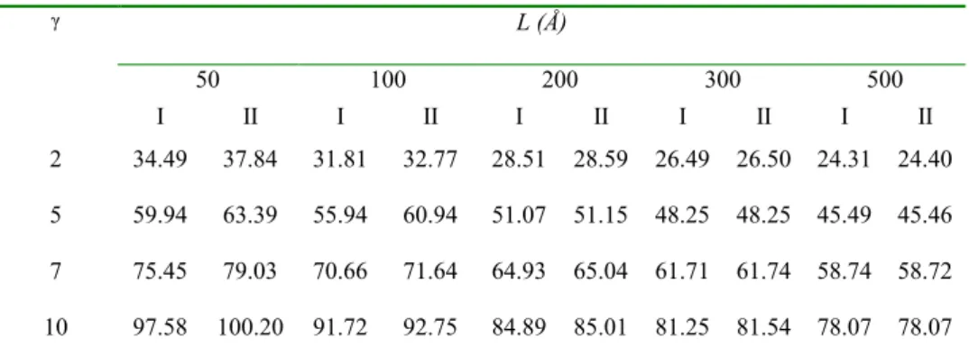
The variation of ionization energy with magnetic field in the infinite well model for non-magnetic QW is shown in Table 2. We conclude that the ionization energy increases with mag-netic field for all well dimensions. This result is in agreement with other works [18, 19]. But at the same time the ionization energy due to PDEM is always greater than the ionization en-ergy due to constant effective mass for all well dimensions L≤a∗.We found similar enhancements in an electric field in our earlier work [20]. The ionization energies of Ref [18, 19] are somewhat lower than our results. This is due to the neglect of the magnetic field effect on the subband energies in those references.
The results for the variation of subband energy for a finite barrier magnetic quantum well, in the presence of magnetic field, shows that the subband energy decreases as the well size
increases, which is a consequence of quantum size effect. The PDEM drastically reduces the subband energy up toL=100 ˚A for all applied magnetic fields. It also follows that the effect of PDEM is unimportant when the well dimension is greater than the effective Bohr radius.
We have also seen how the subband energy varies with well size in the presence of a magnetic field in a finite non –magnetic QW. In general, the PDEM affects the subband en-ergies for narrow wells such thatL≤a∗.Also the subband energy decreases in the presence of PDEM.
0 20 40 60 80 100 120 140 160
0 200 400 600 800 1000 1200
Well size(Å)
Eion(
me
V)
gamma=2 with m =const gamma=2 with m*(z) gamma=10 with m=const gamma=10 with m*(z)
FIG. 3: Variation of ionization energy with well size-finite barrier model.
Figure 3 shows the results of the variation of ionization en-ergy of non –magnetic QW with finite barrier, in the presence of two different magnetic fields. In the case of strong applied magnetic field, we observe that the ionization energy due to m∗(z)is greater than the ionization energy due to constant effective mass.
20 30 40 50 60 70 80 90
0 2 4 6 8 10 12
gamma
Esu
b
(m
eV)
m=0.067 m*(z)
FIG. 4: Variation of subband energy with magnetic field for L=100 ˚A.
Figure 4 shows the variation of sub band energy with mag-netic field for the finite non –magmag-netic QW having the dimen-sion of 100 ˚A for constant effective mass and PDEM. The effect of PDEM on the sub band energy is appreciable.
en-TABLE II: Variation of effective mass in the well region for two different models.
# In all cases I and II refer to m* =0.067 a.u and m*(z) respectively.
L (Å)
50 100 200 300 500
!
I II I II I II I II I II
2 34.49 37.84 31.81 32.77 28.51 28.59 26.49 26.50 24.31 24.40
5 59.94 63.39 55.94 60.94 51.07 51.15 48.25 48.25 45.49 45.46
7 75.45 79.03 70.66 71.64 64.93 65.04 61.71 61.74 58.74 58.72
10 97.58 100.20 91.72 92.75 84.89 85.01 81.25 81.54 78.07 78.07
γ
γ γ γ γ γ γ γ
30 32 34 36 38 40 42 44 46
0 100 200 300 400 500 600
Well size(Å)
Eio
n
(m
eV)
m=0.096 a.u & V=126.89 meV
m=m*( z) & V=126.89 meV
FIG. 5: Variation of ionization energy with well size in the finite barrier model for CdTe-Cd(1-x)Mn(x)Te system.
ergy in a finite magnetic QW in the presence of magnetic field for two different masses in Fig. 5. A similar trend is observed. The variation of sub band energy with well size for the in-finite magnetic QW in the absence of magnetic field has also been investigated. The effect of PDEM is low for well dimen-sionsL≤a∗.
In the QW case the applicability of EMT requires the fol-lowing criterion has to be satisfied. SinceEion/∆E1,2should be<<1, where∆E1,2is the separation between the first two subbands anda∗/Lshould also be less than 1, we obtain the following criterion:Eiona∗/∆E1,2L<<1.
To calculate the energy of the first excited sub band, we have chosen a wave function
ψ3 = N4e−αρ 2
e−βz2sin
µ2π
z L
|z| ≤ L
2 in the infinite well case, ψ4 = N5e−αρ
2
e−βz2sin(δz) |z| ≤L
2
= N6e−αρ2e−βz2e−ξ|z| |z| ≥ L
2 in the finite well case
and followed the variational method [12] to obtain the energy. These wave functions may be easily seen to be orthogonal to the ground state subband wave functions, Eqs. (4) and (7). The obtained results are summarized in Table 3 and Table 4. In all cases, as can be seen from these tables, the EMT is not violated irrespective of whether one uses the constant effective mass or a PEDM.
The second criterion for the validity of EMT, as given in the introduction, demands
|
κ
|
/
κBZππ
1
. This condition is automatically satisfied for shallow donors in bulk semicon-ductors, sincea
/
a
∗ππ
1
. However, in superlattice systems one may have to consider mini Brillouin zones for which κBZ ∼=π/L, where L is the super lattice period. Hence thecriterion
|
κ
|
/
κBZ
∼
=
L
/
π
a
∗π
1
, for GaAs, would meanLπ300 ˚A. However, in the case of an isolated quantum well, which alone is considered in the present work, this criterion coincides with the above, as in bulk.
VI. CONCLUSIONS
In this work, we have considered the effects of PDEM and magnetic field in the estimation of donor ionization energies of GaAs-Ga1−xAlxAs and CdTe-Cd1−xMnxTe quantum wells
vio-TABLE III: Validity of EMT for an isolated non-magnetic inifinite quantum well in different magnetic fields$.
$ I and II are as in Table2.; # E ion (!)=
(((( ))))
γ
ε
a∗∗∗∗e 2
2
E2 sub
(meV)
(((( )))) (((( ))))
(((( ))))
L Ea Eion
γ
γ
γ
2 , 1
*
∆ #
γ=2 γ=5 γ=10 γ=0 γ =2 γ=5 γ=10 Well
size (Å)
I II I II I II I II I II I II I II
50 908.65 579.54 925.72 593.51 954.17 616.79 0.017 0.026 0.017 0.027 0.017 0.027 0.017 0.027
100 235.70 203.06 252.77 218.92 281.22 245.36 0.034 0.039 0.034 0.039 0.034 0.039 0.034 0.039
200 67.46 66.13 84.53 83.02 112.98 111.17 0.068 0.069 0.068 0.069 0.068 0.069 0.068 0.069
500 20.35 20.35 37.42 37.42 65.87 65.87 0.169 0.169 0.169 0.169 0.169 0.169 0.169 0.169
TABLE IV: Validity of EMT for an isolated non-magnetic finite quantum well in different magnetic fields∗.
* I and II are as in Table2. E2 sub
(meV)
(((( )))) (((( ))))
(((( ))))
L Ea Eion
γ
γ
γ
2 , 1
*
∆
γ
=0γ
=2γ
=5γ
=0γ
=2γ
=5 Wellsize
(Å)
I II I II I II I II I II I II
100 108.54 99.05 119.67 94.01 136.74 115.92 0.072 0.079 0.072 0.086 0.072 0.082
200 39.32 38.24 50.58 46.52 67.65 64.03 0.097 0.101 0.097 0.104 0.097 0.102
500 7.78 7.68 19.14 18.66 36.21 35.55 0.195 0.198 0.196 0.202 0.196 0.206
lation of EMT in isolated QW cases. The effect of PDEM on the critical concentrations of donors for Metal-Insulator Tran-sition (MIT) in QW systems will form the basis for another publication.
We hope that the present work will be useful in interpret-ing all the experimental data relevant to optical and electronic properties of doped QW systems as the EMT is vigorously tested and found to be valid.
[1] W. Kohn, Solid State Phys.5, 257 (1957).
[2] R. Resta,In Crystalline Semiconducting Materials and Devices,
edited by P. N. Butcher, N. H. March, and M. P. Tosi (Plenum Press) 217, 1986.
[3] M. Altarelli, W. Y. Hsu, Phys. Rev. Lett.43, 1346 (1979). [4] G. Bastard, Phys. Rev. B24, 4714 (1981).
[5] K. Goser, P. Golsekotter, and J. Dienstubl,Nano electronics and Nano systems (Springer-verlag, Newyork) 2004.
[6] R. K. Willardson, A. C. Beer, and E. R. Weber Ed,Nano Struc-tural systems-Semiconductors and Semimetals35, (1992) [7] V. Mlinar, M. Tadic, B. Partoens, and F. M. Peeters, Phys. Rev.
B71, 205305 (2005).
[8] C. Priester, G. Allan, and M. Lannoo, Phys. Rev. B28, 7194 (1983).
[9] G. T. Einevoll, Phys. Rev. B 42, 3497 (1990).
[10] A. John Peter, K. Gnanasekar, and K. Navaneethakrishnan, Eur. Phys. J. B53, 283 (2006).
[11] S. Rajashabala, K. Navaneethakrishnan, Mod. Phys. Lett. B20, 1529 (2006).
[12] L. I. Schiff,Quantum Mechanics 3rd Edition (McGraw Hill, Singapore) 1968.
[13] Y. Yafet, R. Keyes, and E. N. Adams, J. Phys. Chem. Solids1, 137 (1956).
[14] A. Elangovan, K. Navaneethakrishnan, J. Phys. Condensed Matter5, 4021 (1993).
[15] Yu-Xian-Li, Jian-Jun Liu, and Xiao-Jun Kong, J. App. Phys.88, 2588 (2000).
[16] X.-H.Qi, X.-J.Kong, J.-J.Liu, Phys. Rev. B58, 10578 (1998). [17] S. G. Jayam, K. Navaneethakrishnan, Int. J. Mod. Phys. B 16,
[18] F. Long, P. Harrison, and W. E. Hagston, J. Appl. Phys.79,6939 (1996).
[19] R. L. Greene, K. K. Bajaj, Phys. Rev.B31, 913 (1985).