UNSTEADY FLOW AND LOAD IN 50%
PARTIAL ADMISSION CONTROL STAGE WITH
DIFFERENT ADMITTING ARC DISTRIBUTIONS
by
Ke-Ke GAO, Shun-Sen WANG*, and Dong-Bo SHI
School of Energy and Power Engineering, Xi’an Jiaotong University, Xi’an, China
Original scientific paper DOI: 10.2298/TSCI160201203G
Full 3-D unsteady numerical investigation on an axial air turbine in 50% partial admission is conducted. The partial admission turbines are under different un-steady loading and unloading process, as well as flow parameters, respectively. The loss coefficient and static pressure distributions at the key position are pre-sented in detail to analyze the non-uniformity originated from partial admission. The results show that the non-uniformity decreases along flow direction and the efficiency of control stage also decreases but with the uniformity improved down-stream of the rotors with increasing admitting numbers in equal partial admission degree. The reasons for efficiency decreasing are reasonably explained with windage and sector end losses presented by static entropy distributions. The peri-odic changes of unsteady forces in amplitude and direction are also compared and transformed in the frequency domain by fast Fourer transform method. The larg-est circumferential exciting force factor which is remarkably larger than the cor-responding axial exciting force factor decreases by 13.2% with the increase of admitting arc number. Compared with the common distribution of two symmetric admitting arcs, the maximum exciting force factor of triangle admitting arc distri-bution drops 11.3% with the mere efficiency decrease of 1.32%. The multiple ad-mitting arc turbines are more conducive to be applied to submarines which con-cerns more about exciting force other than efficiency. Efficiency and unsteady forces are both worth being taken into consideration in the practical applications.
Key words: unsteady, partial admission, flow parameters, exciting force
Introduction
Extremely strong unsteady phenomenon is existed in control stage, especially for partial admission turbine. The partial admission turbine is necessary to keep dimensions large through fewer inlet annulus so that the turbine efficiency can be effectively improved. Mean-while, the rotor blades bear loading and unloading process dramatically owning to partial ad-mission. Therefore, the investigation of unsteady influence on partial admission turbine is vi-tal to keep safe and effective operation.
The partial admission turbine performance of impulse design was addressed by Ohlsson [1] through theoretical method. Simplifications including incompressibility, friction-less parameters and no leakage were applied. The 2-D numerical investigation by He [2] pointed out that the enhancing mixing loss can have a positive effect on the overall turbine performance. The unsteady flow characteristics must be considered to investigate the nature ––––––––––––––
of partial admission turbine [3]. The 3-D unsteady performance research with different admis-sion degrees was performed by Xie et al. [4]. The unsteady force relationship of different ad-mission degrees has been revealed. The different numerical models of axial turbine with a low reaction degree were compared by Hushmandi [5]. The 3-D influence on flow parameters was obvious comparing to 2-D model. Experimental investigation on partial admission effects were conducted by Cho et al. [6, 7]. The inhomogeneous flow attenuation and structure in 4-stage turbine was shown by experimental measure and reported by Bohn [8]. Fridh et al. [9] conducted experimental research in partial admission air turbine and the comparison with 2-D compressible model demonstrated the importance of radial components.
The comparable research on the unsteady flow parameters of four vital types of dif-ferent admitting arc distributions in 50% partial admission has been conducted comprehen-sively and thoroughly. The loss parameters, efficiency variation, traverse pressure, and operat-ing forces are analyzed in detail to obtain the relationship with the admittoperat-ing arcs.
Computational geometry and flow conditions
The single stage axial turbine is investigated using ideal air as working fluid in the paper. The air turbine includes 40 straight stators and 65 straight rotors over the full annulus. The blocked arcs with different arc length are included to simulate the unsteady flow of four types of partial admission. The 50% partial admission turbine geometries shown in fig. 1 are achieved by the blocked arcs that are single or evenly divided with optimized admitting dis-tributions. The single blocked arc which is placed upstream of the stator’s leading edge occupies half of whole annulus in case 1. The two blocked arcs are symmetrically arranged upstream of stator’s leading edge in case 2. The three blocked arcs are placed upstream of the stator’s leading edge with triangle distribu-tion in case 3. The four blocked arcs are also symmetrical arranged upstream of stator’s leading edge in case 4. The grids near the wall are refined to obtain accurate flow parameters. Furthermore, the grid independence verification has been done in previous articles to utilize the computational resources effectively [4].
Governing equations and boundary conditions
The equations governing the fluid dynamics are based on the conservation equations of mass, momentum, and energy. The momentum theorem can be expressed:
dV F
d
m t
d =d
d d
(1)
Considering the gravity and stress tensor, infinitesimal control volume force can be obtained through eq. (2), namely:
F g
dd =ρ d d dd x y z+ ∇Πijd d dx y z (2)
According to Reynolds transport theorem, eq. (3) can be derived, where the speed variation is decomposed into the variation with time and space:
dV V V V V dt dt udx vdy wdz
∂ ∂ ∂ ∂
= + + +
d d d d d
(3)
By substituting the eqs. (2) and (3) into eq. (1), the following general form for mo-ment equation can be obtained, namely:
V V V V
g
d d d d
ρ∂ + ∂ + ∂ + ∂ =ρ + ∇
d d d d
d
ij
u v w
t x y z Π (4)
2 3
d µ∂ ∂ d ∂
= − + + − ∂ ∂ ∂ j i k
ij ij ij
j i k
u
u u
p
x x x
Π (5)
where
d
ij is Kronecker delta function (if i=j,d
ij= 1, elsed
ij= 0).Turbulence modeling is the process in which the turbulence stress term solutions in Reynolds equations are closed. Random number generation k-ε turbulence model which is val-idated to have a good agreement with experiment by Hushmandi [5] is chosen as an acceptable accuracy and reasonable amount of calculation time for the investigation in the paper.
eff
( ) ( i) k k b M
i j j
k
k ku G G Y
t ρ x ρ x α µ x ρe
∂ + ∂ = ∂ ∂ + + − −
∂ ∂ ∂ ∂ (6)
2
eff 1 3 2
( ) ( i) ( k b)
i j j
u C G C G C R
t x x e x e k e e k e
e e e
ρe ρe α µ ρ
∂ + ∂ = ∂ ∂ + + − −
∂ ∂ ∂ ∂ (7)
where Gk represents the production of turbulence kinetic energy. The compressibility effect can be explained through a dilatation dissipation term YM., namely
2 t
2 .
M
Y =
ρe
MThe term in the transport equation Recan be expressed:
3 2 0 3 1 1 C R k µ e η ρη η e βη − = + (8)
The transient frozen rotor method is applied to the interface between stators and ro-tors. High accuracy discretization schemes presented by Barth et al. [10] are applied to the convective term discretization. Virtual and true time step are introduced to the time discretiza-tion to avoid the restricdiscretiza-tion of time step length in explicit scheme and the complicated trans-formation of implicit scheme [11]. Thus, we have:
1 1
3
( )
2
q q q n n
q
U U U U U
R U t
t
+ − − + −
+ = −
∆ ∆ (9)
Results and discussion
Loss coefficient
In this paper, the loss coefficient in which entropy rise is used to characterize stage loss is defined by [12]:
s,out
,out s,out
o
T s
h h
ζ = ∆
− (10)
where ∆smeans the entropy production and Ts,outis the static temperature of outlet.
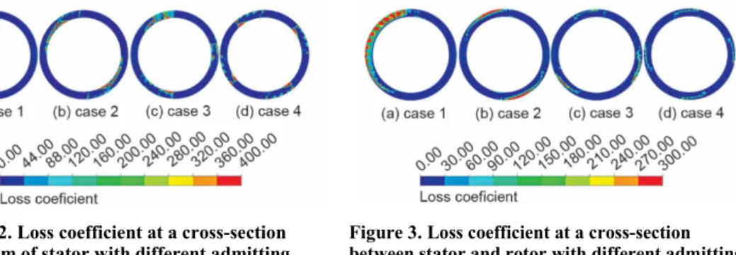
The loss coefficient upstream of stator with four distributions is plotted in fig. 2. The appropriate ranges of loss contours are provided to increase the clarity of results. It is clear that the loss coefficient is affected most strongly for the partial admission with one blockage owing to the stagnation flow. The loss coefficient decreases with the increasing blocked arcs at the position.
The loss coefficient at the cross-section between stator and rotor is plotted in fig. 3. The main loss also exists in the blocked arcs. The loss coefficient of the turbine with four small blocked arcs is lower than the other three blocked arc model comparably at the position. The influence of stagnation flow on the control stage with single blockage is much greater than others.
Figure 2. Loss coefficient at a cross-section upstream of stator with different admitting distributions (for color image see journal web-site)
Figure 3. Loss coefficient at a cross-section between stator and rotor with different admitting distributions (for color image see journal web-site)
The loss coefficient at the cross-section downstream of rotor is plotted in fig. 4. It is easy to find that the loss region influenced by partial admission increases with the augmenta-tion of blocked arcs. The blocked region of case 1 is most seriously affected by partial admis-sion but with a relatively smaller region. Only control stage efficiency considered, case 1 can
operate better due to the smallest affected re-gion. But the phenomenon that the uniformity of exit flow is strengthened with the blocked arcs increasing can be beneficial for the stage downstream, relatively.
Traverse static entropy, pressure, and efficiency
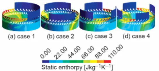
Additional aerodynamic losses are gen-erated by partial admission, blade windage
and sector end losses, respectively. The loss de-velopment process can be easily indentified from traverse static entropy distribution plotted in fig. 5. The rotor blades corresponding to blocked arcs act as the role of fan resulting in windage loss. The sector end loss occurs in the transitional region when the rotors pass through the admitting arcs from blockage and through blockage from admitting arcs. The empty of ro-tor passages and extremely unsteady flow from the last stator generate losses, respectively. The sector end loss is in direct proportional to ad-mitting arc number while windage loss is influ-enced less according to equations [13].
The windage loss is expressed by:
3
wind
o (1 e) U X
e C
−
∝
(11)
The sector end loss is:
segm bl segm
o U
X N
C
η
∝
(12)
The results of the static efficiency and total efficiency varying with the number of blocked arcs are shown in fig. 6. It is easy to conclude that the increasing number of blocked arcs reduces the efficiency of control stage in equal admitting degree. The largest efficiency dif-ference occurs between single blockage and two-symmetric blockage. It is worth pointing out that the influence generated by the number of blocked arcs on efficiency gradually decreases with the increasing number of blocked arcs. The total efficiency and the static efficiency of tri-angle distribution are 1.40%, 0.9% lower than two-symmetric distribution, respectively.
The circumferential static pressure distributions are presented at three cross-sec-tions in the selected two kinds of 50% partial admission turbine in fig. 7. All the static pressure values are normalized with inlet total pressure. Large static pressure drop is found
Figure 7. Circumferential static pressure coefficient at 50% blade height; (a) case 1, (b) case 3 Figure 5. Static entropy distribution at 50% blade height with different admitting
distributions (for color image see journal web-site)
when the rotor passes through the blocked arcs upstream of stator and the position be-tween stator and rotor. The static pressure rises rapidly at the entrance to admitting arcs. The non-uniformity originated from the partial admission decreases along the expansion direction, relatively.
Rotor blade forces
The axial and circumferential forces of rotor blades traveling along the circumfer-ence in the two selected kinds of 50% partial admission turbine are presented in fig. 8. The ro-tor blades experience unsteady loading including variation of magnitude and direction due to partial admission. The rotor blades are also under the periodic axial and circumferential force approximately in the admitting arcs due to the stator wakes. The circumferential force rises suddenly at the entrance to blocked arcs and then decreases rapidly owing to the stagnation fluid while the axial force decreases directly.
Figure 8. Transients of circumferential and axial force at rotor blade; (a) case1, (b) case 3
The fast Fourier transform plays an extremely important role in comparing the fre-quency components of exciting force. The spectral function is defined as:
2π
0 1
( )e d 2π
−
=
∫
iktk
p x t t (13)
The exciting force factor is defined:
k k
p S
x
= (14)
The low frequency exciting force connected with the admitting arcs numbers and ro-tational speed closely can be defined as eq. (15), for the spacing distribution of admitting arcs:
60 k
n
f =kN (15)
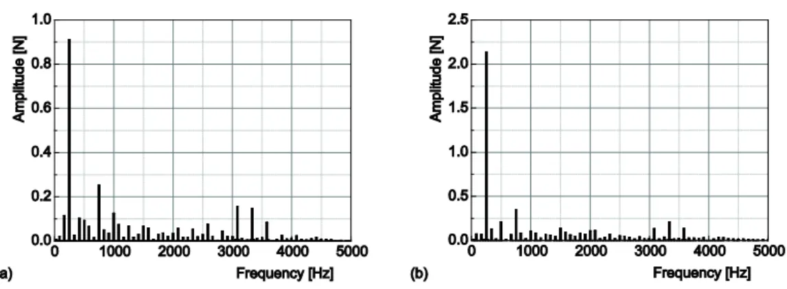
Figure 9. Axial (a) and circumferential (b) forces of rotor in case 3 in frequency domain
The exciting force factor plotted in fig. 10 is applied to conduct reasonable compari-son according to eq. (14). The axial exciting factors increase mainly due to the decreasing av-erage axial force originated from reduction of
the pressure gradient before and after rotor blades with the number of admitting arcs in 50% partial admission. The circumferential exciting force factors have declined in gen-eral, 0.319, 0.309, 0.274, and 0.277, respec-tively. The largest decrease of circumferential force factors occurs between two symmetric distribution and triangle distribution. Com-pared to the common distribution of two symmetric admitting arcs, the maximum excit-ing force factor of triangle admittexcit-ing arc dis-tribution drops 11.3%. The largest increase in axial force factor appears at transition from the triangle distribution to four-symmetric dis-tribution while the axial force remains low.
And the frequency of vibrations has multiplied compared to that of single admitting arc, 81.7 Hz, 166.7 Hz, 249.9 Hz, and 333.3 Hz, respectively. The decrease of circumferential exciting force factors has important application value on special occasions. The frequency improve-ment is of benefit to avoid the low natural frequency of turbine in the same partial degree.
Conclusions
Full 3-D unsteady numerical investigations of four types of 50% partial admission distributions have been conducted in the paper. The in-depth comparative study of unsteady aerodynamic parameters in the four partial admission turbines has been performed.
Firstly, the loss coefficients at the position upstream of the stators, the interface of rotors and stators and downstream of the rotors are plotted in detail in the paper, respectively. It can be found that the influence of partial admission is weakened from upstream to down-stream passage. The exit flow of control stage with single blockage is under the largest non- -uniformity though operating with highest control stage efficiency. The additional losses
inated from partial admission increase with the number of admitting arcs and the decrease of efficiency remains low beginning with symmetrical two admitting arcs.
Secondly, the largest axial and circumferential exciting forces occur at the first order low frequency in the four 50% partial admission. The largest amplitude of circumferential ex-citing forces which is remarkably larger than the corresponding axial exex-citing forces decreas-es by 13.2% with the increasing number of admitting arcs. Compared to the common distribu-tion of two symmetric admitting arcs, the maximum exciting force factor of triangle admitting arc distribution drops 11.3% with the mere efficiency decrease of 1.32%. The frequency of exciting forces has multiplied with the increasing number of admitting arcs compared with that of single admitting arcs. The equal partial admission turbine with more admitting arcs is beneficial to decrease overall exciting force to guarantee the safe operation. And the frequen-cy improvement along with the increasing number of admitting arcs can be used to avoid the low natural frequency of turbine in the same partial admission degree.
Nomenclature
C – spouting velocity, [ms–1]
C1ε, C2ε – model constant, [–]
C3ε – variables which determine how
dissipation rate is affected with buoyancy, [–]
Cμ – modified constant, [–]
e – partial admission degree, [–] F
d
– force, [N]
f – frequency, [Hz]
Gb – generation of turbulence due to
buoyancy, [–] h – enthalpy, [kJkg–1]
k – kinetic energy of turbulence, [kJ]
Mt – turbulent Mach number, [–]
m – mass, [kg]
N – the number of admitting arcs, [–]
n – rotation speed, [rmin–1]
p – exciting force, [N]
R – discrete function, [–]
S – exciting force factor, [–]
s – static entropy, [kJkg–1K–1]
T – temperature, [K]
t – time, [s]
U – circumferential velocity, [ms–1]
u, v, w – velocity components in a generalized co-ordinate system, [ms–1]
Vd – velocity, [ms–1]
X – loss factor, [–]
x – average force, [N]
Greek symbols
αk – inverse effective Prandtl numbers, [–] β – coefficient of thermal expansion, [–] ε – dissipation rate, [–]
ζ – loss coefficient, [–] η – efficiency, [–]
μeff – effective dynamic viscosity
coefficient, [Pa·s] ij
Π – stress tensor, [–] ρ – density, [kgm–3] τ – virtual time, [s]
Subscripts
bl – blade in – inlet
k – the order of exciting force
o – ideal out – outlet s – static segm – sector end t – total wind – windage
μ – dynamic viscosity coefficient
Superscripts
q, n – discrete points serial number
References
[1] Ohlsson, G. O., Partial-Admission Turbines, Journal of Aerospace Science, 29 (1962), 9, pp. 1017-1028 [2] He, L., Computation of Unsteady Flow Through Steam Turbine Blade Rows at Partial Admission,
Proceedings, Institution of Mechanical Engineers, Part A: Journal of Power and Energy, 211 (1997), 3, pp. 197-205
[4] Xie, Y., et al., Computational Fluid Dynamics Modeling Three-Dimensional Unsteady Turbulent Flow and Excitation Force in Partial Admission Air Turbine, Mathematical Problems in Engineering, 2013
(2013), ID 251926
[5] Hushmandi, N. B., Numerical Analysis of Partial Admission in Axial Turbines, Ph. D. thesis, KTH Industrial Engineering and Management, Stockholm, 2010
[6] Cho, S. Y., et al., Forces and Surface Ppressure on a Blade Moving in front of the Admission Region,
Journal of Fluid Mechanics,132 (2010), 12, pp. 1-8
[7] Cho, S. Y., et al., Pressure and Force on a Blade Rrow Operated in Partial Admission with Different Solidity, Journal of Mechanical Science and Technology, 27 (2013), 2, pp. 387-396
[8] Bohn, D. E., et al., Expeimental Investigation into the Non-Uniform Flow in a 4-Stage Turbine with Special Focus on the Flow Equalization in the First Turbine Stage, Proceedings, ASME Turbo Expro 2003, Power for Land, Sea, and Air, Atlanta, Geo., USA, 2003, GT-2003-38547
[9] Fridh, J. E., et al., An Experimental Study on Partial Admission in a Two-Stage Axial Air Test Turbine with Numerical Comparisons, Proceedings, ASME Turbo Expro 2003, Power for Land, Sea, and Air, Vienna, 2004, GT-2004-53774
[10]Barth, T. J., et al., The Design and Application of Upwind Schemes on Unstructured Meshes,
Proceedings, 27th AIAA Aerospace Sciences Meeting, Reno, Nev., USA, 1989, AIAA -89-0366 [11]Jameson, A., Time Dependent Calculations Using a Multigrid with Applications to Unsteady Flows Past
Airfoils and Wings, 10th AIAA Computational Fluid Dynamics Conference, Honolulu, Hi., USA, 1991, AIAA -91-1596
[12]Denton, J. D., The 1993 IGTI Scholar Lecture: Loss Mechanisms in Turbomachines, Journal of Tur-bomachinery, 115 (1993), 4, pp. 621-656
[13]Moroz, L., et al., Analysis and Optimization of Partial Admission Stages, Proceedings, Asian Congress on Gas Turbines 2014, Seoul, 2014, ACGT-2014-0007