Influence of Fabrication Process on the Final Properties of
Natural-Rubber Latex Tubes for Vascular Prosthesis
W. F. P. Neves-Junior, M. Ferreira, M. C. O. Alves, C. F. O. Graeff, M. Mulato, Departamento de F´ısica e Matem´atica, Faculdade de Filosofia Ciˆencias e Letras de Ribeir˜ao Preto,
Universidade de S˜ao Paulo, Av. Bandeirantes 3900, Ribeir˜ao Preto, SP, 14040-901, Brazil
J. Coutinho-Netto,
Departamento de Bioqu´ımica, Faculdade de Medicina de Ribeir˜ao Preto, Universidade de S˜ao Paulo, Brazil
and M. S. Bernardes
Escola Superior de Agricultura Luiz de Queiroz, Universidade de S ˜ao Paulo, Piracicaba, Brazil
Received on 7 February, 2006
We report a process of fabrication of latex tubes using the dip-coating technique. We investigated cen-trifuged latex, with different original viscosities, extracted from the Hevea brasiliensis. The influence of the main deposition parameters (dip-coating velocity, mold material, mold diameter and number of coatings) and post-deposition drying process parameters (temperature and time) on the properties of the final samples are in-vestigated and discussed. Additional investigation about the elastic behavior of the tubes is presented for strain values up to rupture. The rupture occurred at 120 mm for tubes 15 mm-long, which represents an elongation of 800%. The tubes presented two distinct elastic mechanisms, with the most elastic one being observed below an elongation of about 500%. During a cycled strain experiment with strain values below the rupture point, a hysteretic-like curve was observed, which was related to the uncurling and recurling of the polymeric chains.
Keywords: Vascular prosthesis; Hevea brasiliensis; Natural rubber latex; Dip-coating fabrication
I. INTRODUCTION
It was recently claimed that the natural rubber latex, ex-tracted from theHevea brasilliensis, is a strong candidate to be used as a biomaterial [1-3]. This biologically compatible material can be used in contact or inside the human body. In addition, it performs a biological action that accelerates the healing process, being a powerful stimulator of cicatrisation [1]. Latex induces angiogenesis and neo-formation of tis-sues [1,4], which makes it useful as a band-aid curative for the treatment of ulcers in diabetic patients [5]. Also, it is well known that dried latex, in the rubber form, presents high resis-tance, high elasticity and is an easy-shaping material, which increases its appeal for the use in the fabrication of vascu-lar prosthesis. Some previous works studied the use of natural rubber latex to fabricate tubes to be implanted into the abdom-inal aorta of dogs [6]. There were good results as compared with the elasticity of natural rubber, which is a very impor-tant quality to produce vascular prosthesis. On the other hand, the same study has shown that rubber presents a poor capac-ity of neo-intima formation and that there is clot formation in most of the implanted tubes. Additional studies suggested that deficiencies in neo-intima formation between the host artery and rubber can be minimized by the addition of electronega-tive substances [7]. Sharp demonstrated that both natural and synthetic coat rubbers, with an electrical conductive layer, in-creased the prostheses performance in the transplanted ani-mals [7,8].
Many polymeric materials, such as polyethylene thereph-thalate (PET) [9], polyurethane (SPU) [10,11] and polyte-trafluoroethylene (PTFE, ePTFE) [12], have been used in the development of vascular prosthesis, with good results in terms
of biocompatibility.
The matching of the compliance between the prosthesis and the circulatory system is as important as the control of the prosthesis dimensions. Both must be completely controlled in the manufacturing process for the success of the tube-like im-plants [13]. The tubes must have regular and uniform walls, being available on a variety of sizes and diameters, and have to work in the vascular system as the original arteries to avoid thrombogenesis. All these variables depend on the fabrica-tion method and also on the raw material properties. In or-der to fabricate applicable prosthesis, it is necessary to un-derstand how these variables are connected, and how they in-terfere on the physical characteristics of the final product. In this sense, the higher versatility and moldability of latex, com-pared to other industrial candidates, might increase its chances to present an improved mechanical performance when fitted into the vascular system.
also present some preliminary data about the elasticity of the non-porous fabricated tubes.
II. EXPERIMENTAL METHODOLOGY
The original latex used in this work consists of a mixture of a non-controlled variety of milks extracted from different trees (variances ofHevea brasiliensis). It is the same mater-ial that has been used in the medical applications cited before [1-5]. After the extraction, the material is centrifuged and the pH is corrected to about 10 using an ammoniac solution in or-der to avoid coagulation. A mixture of 4% sulphur and 2% polyvinyl methyl-ether resin is also added to the latex leading to a viscous and consistent material. This work is based on two different starting latex samples, with different viscosities, which will be called Latex-1 (higher viscosity) and Latex-2 (lower viscosity). They were subjected to a rheologic test [14, 15] (viscosity as function of the shear gradient) using a rota-tional viscometer Rheotest 2.
The fabrication process is based on the dip-coating tech-nique. Cylindrical molds are vertically introduced into a latex bath at a constant speed of 5 centimeters per minute, in most of the cases. On occasional experiments to be described below, this speed was changed. The mold is then removed from the bath at the same speed. Given that the viscosity of the latex of the original bath might change as a function of the amount of ammonia, during all the depositions, extra care was taken to avoid or minimize the loss of ammonia. Six centimeters-long molds of several diameters (from 3 to 6 mm) made of glass and Teflon°Rwere used. All the samples were made at room
temperature (25 ˚ C).
Immediately after the bath, the dip-coated mold was taken into an oven to be dried. The standard drying process was performed at 65±3oC for about 20 minutes. All this method-ology can be repeated with the same mold to increase the final thickness of the wall of the latex tube, which is then removed from the mold.
We studied the role of some of the main fabrication para-meters on the properties of the final tube. We investigated the thickness of the wall of the final tube as a function of i) the diameter of the mold (3 to 6 mm), ii) the number of coat-ings (1 to 5), iii) the variation of the velocity of the dip-coating process (4 to 20 cm/min), iv) the mold material (either glass or Teflon°R), and v) the viscosity of the original bath (see Fig.1).
After the deposition, all the samples were subjected to the same standard thermal treatment (65±3oC, for 20 minutes). After that, their external diameter was measured (while still on the mold), with a digital caliper at different positions along the tube.
We carried out an additional investigation to understand and optimize the drying process. The mass loss during the thermal treatment is analyzed as a function of temperature and time of treatment. This study was performed with the glass substrate with a diameter of 5 mm, dipped one time in the latex bath. We analyzed both Latex-1 and Latex-2 using drying tempera-tures varying from 30oC up to 100oC (±5oC) and drying times of 30 seconds up to 30 minutes. Initially, we deposited a
la-tex layer on the mold and weighed it at a precision balance. After that the mold was taken to the oven for the desired treat-ment. After the desired time the mold was quickly weighted again, and then took back into the oven. The original mold mass, without the latex layer was taken into account for the necessary corrections. The experiments with Latex-1 had an initial adhesion of 145±2mg, while those with Latex-2 had 33±1mg.
As a preliminary evaluation of the elastic properties of the samples we performed tension-deformation tests, which give information about the elasticity of the tubes that have been produced by the described methodology. We stretched tubes with a diameter of 5 mm and with varying wall thickness using an EMIC-MEM2000 system. The strain velocity was 10mm/min, with a charge cell of 50kgf. The samples had an original length of 15 mm and were stretched until rupture.
III. RESULTS AND DISCUSSIONS
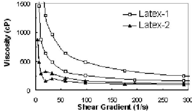
Figure 1 shows the results of the rheologic test for origi-nal latex baths Latex-1 and Latex-2. The viscosity was mea-sured for an increasing shear gradient up to 300 s−1; above
this value, it is almost constant. The viscosity was also mea-sured for a decreasing shear gradient. The experiment was performed with the latex bath inserted between the two cylin-ders of the Rheotest 2, and consists of a measure of the resis-tance imposed by the material to the spinning of the internal cylinder [14, 15].
FIG. 1: Viscosities of the original Latex baths (in Poise) as a function of the shear gradient. Note that Latex-1 is more viscous than Latex-2.
coagulation. In Fig. 1, note that it is difficult to explain that i) Latex-1 exhibited a larger resistance to disorganization than to reorganization, while Latex-2 behaves the opposite way. The arrows in Fig. 1 indicate the sequence of the measurements, and ii) the bump-like profile observed for the measurements of Latex-2 for small values of the shear gradient.
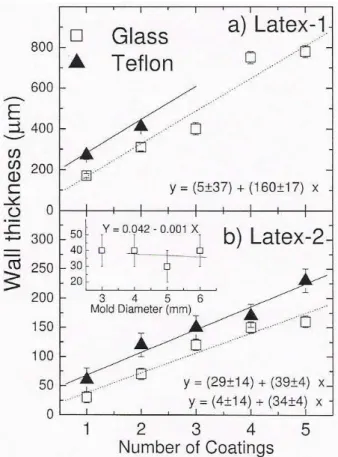
Figure 2 shows the thickness of the wall of the tubes as a function of number of coatings. Two original baths with dif-ferent viscosities were used, Latex-1 (Fig. 2(a)) and Latex-2 (Fig. 2(b)). Two mold materials were used, Glass (represented by squares) and Teflon°R(represented by triangles). In all of these cases, a linear behavior was observed, and the corre-sponding linear fits are shown in the figure. It can be clearly seen that: i) the higher the viscosity, the higher the thickness of the adhered layer; and ii) the mold material has an influ-ence on the first coating only. The variation of adhesion on glass and Teflon°Ris most probably related to the higher sur-face roughness of the Teflon, due to fabrication processing. Glass has a much smoother surface.
FIG. 2: Thickness of the wall of the produced latex tubes as a func-tion of the number of coatings for Latex-1 (a) and Latex-2 (b). Two mold materials were used, glass (squares) and Teflon°R(triangles,) for a mold diameter of 5 mm. Except for the triangles in a), the lines are linear regressions with the respective equations written inside the picture. The inset in b) corresponds to the thickness of the wall of the produced latex tubes using a glass mold with varying diameters and for a single bath.
For the more viscous sample, a stronger dependence of the final thickness on the number of baths was observed, as
ex-pected intuitively. However, depending on the velocity of the dip-coating process, the wall of the tube can grow in a conic-like shape, with the lower part of the mold leading to a thicker wall. This effect is more pronounced with increasing viscos-ity of the starting bath. This can cause a strong deviation in the measurement of the wall of the tubes, as it is the case for Latex-1. Note that the thickness of the samples grown using Latex-2 shows much smaller variations. Also, if the mold is too short, less than 5 cm as is the case for the Teflon°R, this effect is enhanced. This explains why Fig. 2(a) has only two data for the Teflon°Rmold. At standard conditions, after a sin-gle bath and the whole thermal processing, the same adhered latex layer (0,04±0,01mm) is obtained for molds of any di-ameter, as can be seen at the inset of Fig. 2(b). The fact that the standard deviation is equal to the caliper error (0,01mm) means that the tubes were regular and uniform. Regarding the dimensions of the tubes, they might be applicable in substitut-ing arteries and veins such as femoral, coronary, renal, carotid, portions of aorta with small caliber, vena cava etc [16,17].
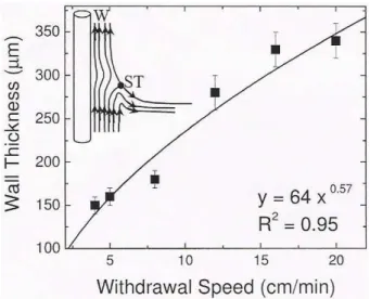
The influence of the velocity of the dip-coating on the final thickness of the wall of the latex tube is presented in Fig. 3. The faster the withdrawal speed, the thicker the adhered latex layer. Empirically, the dependence of adhesion (δ)on velocity (U) can be well described by a power-law. The fitted function is indicated inside the figure, with the correlation coefficient R2=0.95. The classical Landau-Levich law [18,19], derived
for a plane substrate emerging from a large bath of a non-volatile liquid, predicts a dependence ofδon U given by
δ= (U.µ)2/3.B
(ρ.g)1/2.σ1/6
, (1)
whereδis the thickness of the adhered layer, U is the with-drawal velocity,µis the viscosity of the bath,ρis the density,
σthe surface tension, g the acceleration of gravity, and B is a constant determined by matching. This theoretical law pre-dicts that the thickness of the adhered layer increases with in-creasing withdrawal speed. The experimental coefficient dif-fers about 15% from the theoretical prevision of Eq. 1. This difference may be related to the following reasons. The latex used in the experiments was too viscous, which increases the deviations at large velocities due to the irregular growth of the layer that tends to thicken the region closer to the lower ex-tremity of the substrate. Also, the theory was developed for a planar substrate while we used a cylinder.
FIG. 3: Influence of the dip coating velocity on the adhered latex layer. The curve is a power function fitting, where R2is the correla-tion coefficient.
an extreme condition for high enough speeds, the latex prac-tically does not suffer any drainage. Depending on extreme withdrawal speed and bath viscosity, even an increasing ac-cumulation of material up to the substrate extension can be obtained, leading to a conic-like sample. This effect was pre-viously theoretically verified in the literature [19,20].
These experiments discussed the influence of the dip-coating parameters and the latex viscosity on the final thick-ness of the wall of the tubes. As mentioned before, a stan-dard procedure was used for drying the samples after the with-drawal from the bath. They were subjected to thermal treat-ment at 65±5oC for 20 min in the oven. Nevertheless, the temperature and total drying time are also important parame-ters to be investigated either for the understanding of the dry-ing itself or for an optimization of an industrial process. For that purpose, a glass mold with a diameter of 5 mm was used for the fabrication of single-bath samples. A dip-coating ve-locity of 5 cm/min was adopted and we varied the processing temperature from 30 up to 100oC, and the processing time from 0.5 to 30 min. The mass loss was measured as presented before, and the results for a bath using Latex-2 are presented in Fig. 4.
The study of the heating process indicated that the relative mass loss can reach up to 50%. This means that only 50% of the mass of the samples produced using Latex-2 can be con-sidered non-volatile at a temperature of 100oC, the rest can be considered water. These studies also indicated an accelerated mass loss in the first 3 minutes of heating (around 40±5%), in all the cases. This can be better visualized in the inset a) of Fig. 4. After the initial fast ramp, stabilization is observed for processing times above 10 minutes. Fig. 4 also shows that the higher the heating temperature, the larger the mass loss and the lesser the final mass after 30 minutes of heating. Ac-cording to Fig. 4, an optimized processing time of about 10 minutes could be adopted for the future development of vas-cular prosthesis. The inset b) of Fig. 4 shows the rate of mass loss during the first 1.5 minutes of the processing as a function
0 10 20 30 40 50
0 5 10 15 20 25 30
Heating Time (min) Mass Loss (%) 100ºC
75ºC 50ºC 30ºC
0 25 50
0 1 2 3
5 6 7 8 9
25 45 65 85 105
Temperature(ºC)
R
a
te of Mass
Loss(mg/min)
a) b)
FIG. 4: Heating process of Latex-2: Relative mass loss as function of heating time for selected temperatures. The inseta)shows the region of the initial ramp in detail. The insetb)shows the rate of mass loss during the first 1.5 minutes of the processing as a function of temperature; the line is just a guide for the eyes.
of temperature; the line is just a guide for the eyes. The data for this inset were obtained by linearly fitting the first 4 data points of the experiments presented in Fig. 4. It can be con-cluded that the velocity of mass loss rises with temperature, reaching a limit of 9 mg/min for temperatures above 80oC. In-creasing temperatures do not seem to change the initial mass loss rate, even though the total mass loss can be varied as indi-cated by the data taken after 30 minutes of thermal treatment. Even though Fig. 4 presents data for Latex-2 only, the previ-ous conclusion does not depend on the viscosity of the starting material as can be seen in Fig. 5, where the same experiment was performed with an original bath using Latex-1. The most significant difference observed in Fig. 5 is related to the fact that the more viscous latex presents less total mass loss, and smaller initial mass loss rate, representing a slower process. Even after 30 minutes of processing, a Latex-1 sample had a loss of mass of about 43%, while a Latex-2 sample had a loss of about 50%.
0 10 20 30 40 50
0 5 10 15 20 25 30
Heating Time (min)
Mas
s
Los
s
(%
)
100ºC - Latex-2 100ºC - Latex-1 40ºC - Latex-1
FIG. 5: Heating process comparing Latex-1 and Latex-2 (relative mass loss as function of heating time, for selected temperatures).
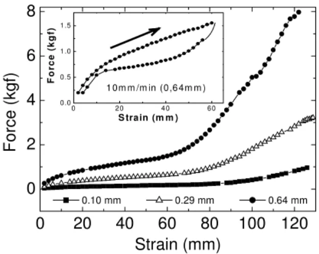
inset of this figure shows the result of an experiment made with the 0.64 mm-thick tube, below the rupture point. The tube was first stretched as indicated by the arrow, showing a hysteretic behavior. The strain velocity was 10 mm/min for all the experiments shown in Fig. 6.
0
20
40
60
80
100 120
0
2
4
6
8
0 20 4 0 60
0.0 0.5 1.0 1.5
F
o
rce (
kg
f)
S train (m m ) 1 0m m /m in (0,6 4m m )
F
o
rc
e (
k
gf
)
Strain (mm)
0.10 mm 0.29 mm 0.64 mm
FIG. 6: Elastic perfprmance of rubber tubes with different wall thick-nesses. The deformation was performed along the z-axis of the tube (i.e. longitudinal direction) up to the rupture point. The original tubes were 15 mm long. The inset shows the result of an experi-ment with a 0.64 mm-thick tube, avoiding rupture. The tube was first stretched, as indicated by the arrow, showing histeresis. The strain velocity was 10 mm/min in all the experiments.
The results of Fig. 6 show that the material presents two dis-tinct elastic behaviors, which are characterized by the slopes of the curves. While the first one dominates at small strains, where the tube is easily stretched, the second one dominates after a 70 mm strain. Above this value, the material requires an increasing force in order to show the same relative defor-mation. The thicker the wall of the tube, the larger must be the force to produce the same strain, indicating that the tubes offer a larger elastic resistance. This dependence of elastic resistance on wall thickness is similar to a system of springs connected in parallel. The fact that the rupture of the tubes oc-curred at the same strain, regardless of wall thickness, might be related to a cascade phenomenon. As some polymer chains start to brake, the net force is applied on a smaller group of chains, each one of them in a larger effective load.
The hysteretic result shown in the inset of Fig. 6, for an ex-periment performed in the range of the most elastic behavior, leads to the conclusion that the material has a strain mem-ory. At rest, the material is made of polymer chains that have some average curling, which leads to a certain elastic con-stant. During the initial stretching, the polymer chains are forced to uncurl, and the elastic constant decreases. When the process is reversed, i.e. when the external force is grad-ually removed, the net keeps a memory of the previous un-curling stage. For instance, at the same strain of 40 mm the material shows two different elastic constants, one of them for the stretching and another one for the relaxation. The smaller elastic constant for the relaxation might be due to the more uncurled state of the polymeric net. When the external force
is further reduced, the net keeps its recurling behavior and for strain below 20 mm the material returns to its original state. These preliminary data shows that the rubber latex tubes are more compliant than other polymer tubes, like segmented polyetherurethane (SPEU), stretching 30% with tensions be-low 100kPa insofar SPEU needs about 700kPa to present the same stretch [18]. The elastic moduli (Young’s Modulus) of the first tested tubes are 270kPa, 210kPa, and 160kPa, re-spectively from the thickest to the thinnest. Comparing these preliminary values with results by Gupta and Kasyanov [16], for the Human Carotid Artery (83.36kPa), two different Tex-tile Hybrid Vascular Grafts (HGV1: 61.81kPa and HGV2: 87.78kPa) and a Commercial Polyester Graft (1074.64kPa), we note that the rubber tubes present an intermediary elastic modulus. The elastic moduli of the rubber tubes are about 2 to 3 times larger than in the case of the Human Carotid Artery, even though these values are better than in the Commercial Polyester Graft. Finally, Gupta and Kasyanov’s experiments explore the volumetric elastic behavior, while we analyzed the longitudinal behavior, which somehow restricts these compar-isons.
The elastic moduli of the rubber tubes are slightly bigger than those reported in the literature for other materials. Nev-ertheless, these values can be easily tailored, for instance by changing the starting concentration of sulphur, which varies the number of cross-links and, consequently, the stiffness of the material as well. A detailed study about the elastic prop-erties of the tubes was published elsewhere [21]. The study of the sulphur influence will be an important further step in this work.
IV. CONCLUSIONS
require a large range of resistance and elasticity.
V. ACKNOWLEDGEMENTS
This work was supported by CNPq / PADCT III Milˆenio, under projects number 62.0061/01-4 (IMMP) and
478452/04-7, and also by Fapesp (03/02516-2). We thank Professors E. H. G. Lara and M. S. Ogasawara, for the experimental assis-tance on the rheologic characterizations, Professor H. Panzeri, R.S. Antunes and E. Volta for the experimental help on the stress-strain assays, and J. L. Aziani for experimental help.
[1] F. Mru´e, Neoformac¸˜ao tecidual induzida por biomembrana de latex natural com polilisina, PhD Thesis, Faculty of Medical Sciences of Ribeir˜ao Preto, University of S˜ao Paulo, 2000. [2] J. A. Thomazini, F. Mrue, J. Coutinho-Netto, J.J. Lachat, R.
Ceneviva, and A. C. Zborowski, Morphological and biochemi-cal characterization of a prosthesis manufactured from natural latex of Hevea brasiliensis for medical utilization. Acta Micro-scopica, v. 6, p. 798-799, 1997.
[3] F. Mrue, J. Coutinho-Netto, R. Ceneviva, J. J. Lachat, J. A. Thomazini, and H. Tambelini, Evaluation of the Biocompati-bility of a New Biomembrane. Materials Research, v. 7, n. 2, p. 277-283, 2004.
[4] M.C.O. Alves, Teste da angiogˆenese estimulada por membranas de l´atex natural, Master Thesis, Faculty of Philosophy, Sciences and Letters of Ribeir˜ao Preto, University of S˜ao Paulo, 2003. [5] M.A.C. Frade, R. V. Valverde, R.V.C. de Assis, J.
Coutinho-Netto, and N.T. Foss, Cronic phlepoppathic cutaneous ulcer: a therapeutic proposal.Int. J. Dermatol.,40(3): 238-240, (2001). [6] W. V. Sharp, W. H. Falor, Rubber latex tubing as a vascu-lar prosthesis, American Journal of Surgery, 105, 802-8811, (1963).
[7] W. V. Sharp, Vascular Prostheses,Transactions American Soci-ety for Artificial and Internal Organs,10, 223-226, (1964). [8] W. V. Sharp, Vascular Prostheses,Transactions American
Soci-ety for Artificial and Internal Organs,11, 336-340, (1965). [9] A. Eberhart, Z. Zhang, R. Guidoin, G. Laroche, L. Guay, D.
De la Faye, M. Batt, and M.W. King, A new generation of polyurethane vascular prostheses: Rara avis or ignis fatuus? J. Biomedical Materials Research,48(4); 546-558, (1999). [10] Y. Nakayama and T. Matsuda, Surface microarchitectural
de-sign in biomedical applications: In vitrotransmural endothe-lialization on microporous segmented polyurethane films fabri-cated using an excimer laser,J. Biomedical Material Research,
31:235-242, (1996).
[11] K. Doi, Y. Nakayama and T. Matsuda, Novel compliant tissue-permeable microporous polyurethane vascular prosthesis fabri-cated using excimer ablation technique,J. Biomedical Material Research,31: 27-33, (1996).
[12] D.Y. Tseng , and E. R. Edelman, Effects of amide and amine plasma-treated ePTFE vascular grafts on endothelial cell lining in an artificial circulatory system.J. Biomedical Materials Re-search,42: 188–198, (1998).
[13] K. Doi and T. Matsuda, Significance of porosity and compli-ance of microporous, polyurethane-based microarterial vessel on neoarterial wall regeneration,J. Biomedical Materials Re-search,37(4): 573-584, (1997).
[14] E.K. Fischer and C.H. Lindsley, Rheological measurements with the rotational viscometer,Textile Research Journal,18(6): 325-337, (1948).
[15] H.A. Barnes, J. F. Hutton, and K. Walters,An introduction to rheology, Elsevier Science Publishers, 1989, Amsterdam. [16] B.S. Gupta and V.A. Kasyanov, Biomechanics of human
com-mon carotid artery and design of novel hybrid textile compliant vascular grafts,J. Biomedical Materials Research,34: 341-349, (1997).
[17] A.C. Burton, Relation of structure to function of the tissue of the wall of blood vessels,Physiol. Rev.,34: 619-642, (1954). [18] L. Landau and B. Levich, Dragging of a liquid by a moving
plate,Acta Physicochim.,17:42-54, (1942).
[19] D. Qu, H. Ram´e and S. Garoff, Dip-coated films of volatile liquids,Physics of Fluids,14(3): 1154-1165, (2002).
[20] L.M. Hocking, Meniscus draw-up and draining,European J. Applied Math.,12,195-208, (2001).