Bruno Salles SOTTO-MAIOR(a)
Camila de Andrade LIMA(b)
Plínio Mendes SENNA(c)
Germana de Villa CAMARGOS(b)
Altair Antoninha DEL BEL CURY(b)
(a) Department of Restorative Dentistry, Dental School, Universidade Federal de Juiz de Fora − UFJF, Juiz de Fora, MG, Brazil. (b) Department of Prosthodontics and
Periodontology, Piracicaba Dental School, University of Campinas − UNICAMP, Piracicaba, SP, Brazil.
(c) Department Health Sciences Center, Unigranrio University, Duque de Caxias, Rio de Janeiro, Brazil.
Biomechanical evaluation of
subcrestal dental implants with
different bone anchorages
Abstract: This study evaluated the biomechanical inluence of apical bone anchorage on a single subcrestal dental implant using three-di-mensional inite element analysis (FEA). Four different bone anchorage designs were simulated on a posterior maxillary segment using one im-plant with platform switching and internal Morse taper connection as follows: 2 mm subcrestal placement with (SW) or without (SO) the im-plant apex engaged into the cortical bone or position at bone level with anchorage only in the crestal cortical (BO) bone or with bicortical ixa-tion (BW). Each implant received a premolar crown, and all models were loaded with 200 N to simulate centric and eccentric occlusion. The peak tensile and compressive stress and strain were calculated at the crestal cortical, trabecular, and apical cortical bone. The vertical and horizontal implant displacements were measured at the platform level. FEA indicat-ed that subcrestal placement (SW and SO) creatindicat-ed lower stress and strain in the crestal cortical bone compared with crestal placement (BO and BW models). The SW model exhibited lesser vertical and horizontal implant micromovement compared with the SO and BO models under eccentric loading; however, stress and strain were higher in the apical cortical bone. The BW model exhibited the lowest implant displacement. These results indicate that subcrestal placement decreases the stress in the crestal cortical bone of dental implants, regardless of apical anchorage; however, apical cortical anchorage can be effective in limiting implant displacement. Further studies are required to evaluate the effects of pos-sible remodeling around the apex on the success of subcrestal implants.
Keywords: Dental Implants; Dental Stress Analysis; Finite Element Analysis.
Introduction
Dental implants are widely used to replace missing teeth, and their clinical success is dependent on the primary stability achieved during implant placement.1 The threshold of movement within the alveolar bone
should be 150 µm so that it does not interfere with the healing process.2 However, in regions of poor bone quality, such as the posterior maxilla,3
adequate primary stability cannot be achieved at bone level, necessitat-ing subcrestal placement.4 Moreover, this deeper position may also be
indicated when there is limited interocclusal height for the restoration and for an esthetic emergence proile.5,6
Declaration of Interests: The authors certify that they have no commercial or associative interest that represents a conflict of interest in connection with the manuscript.
Corresponding Author:
Bruno Salles Sotto-Maior E-mail: [email protected]
DOI: 10.1590/1807-3107BOR-2014.vol28.0023 Epub XXX XX, 2014
Submitted: Aug 14, 2013
Subcrestal implant placement seems to result in more eficient crestal bone preservation when asso-ciated with Morse taper connection and platform switching. 7,8,9 Although a previous study using inite element analysis (FEA) reported that the peak com-pressive stress at the crestal cortical bone was higher around subcrestal implants than around implants placed at bone level,10 other studies reported that subcrestal placement displaces the stress away from the crestal cortical bone.11,12 Therefore, this lower
stress concentration in the crestal cortical bone can
explain the occurrence of osseointegration coronal to the abutment–ixture interface in cases of subcrestal implant placement with Morse taper connection.6
However, in cases of subcrestal implant placement in the maxilla, the implant apex can be engaged into the cortical bone of the nasal or maxillary sinus loor. Bicortical ixation of bone level implants improves primary stability and decreases the stress in the
bone;13 however, the inluence of apical anchorage of
subcrestal implants on stress distribution remains unknown. The change in the fulcrum from the implant cervix toward the apical region may change the stress and strain distribution within the bone and affect its resistance to micromovement.
Therefore, given the limited information cur-rently available on subcrestal implant placement, this study was conducted to evaluate the inluence of apical bone anchorage for a single subcrestal den-tal implant on bone stress and strain and resistance to micromovement using three-dimensional FEA.
Methodology
Three tri-dimensional models of a posterior max-illary segment were developed using the SolidWorks 2011 3D software (SolidWorks Corp., Concord, USA). The models were of different heights (11, 13, and 15 mm) and included a 1-mm-thick uniform cortical bone layer.14 Subsequently, a computer-aided design (CAD)
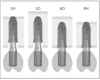
model (Cone Morse Titamax EX; Neodent, Curitiba, Brazil) of a 4.0 × 11-mm Morse taper connection cylin-drical implant was combined with one of the maxil-lary models to allow the construction of four differ-ent cortical bone anchorage designs (Figure 1): 2 mm subcrestal placement with (SW) or without (SO) the implant apex engaged into the cortical bone or
posi-tion at the bone level with anchorage only in the crestal
cortical bone (BO) or with bicortical ixation (BW). After implant positioning, a 3.3-mm diameter abutment CAD model (Munhão Universal CM; Neodent, Curitiba, Brazil) was imported into each model and aligned to the implant. To compensate the implant depth and maintain the same crown height, a 1.5-mm-high abutment was used on the bone level implants and a 3.5-mm-high abutment was used on the subcrestal implants (Figure 1). Next, a solid-dis-play stereolithographic image of a second premolar crown, based on cone-beam computed tomography images (Kodak 9000 3D Extraoral Imaging System; Carestream Dental LLC, Atlanta, USA), was posi-tioned on each abutment, simulating an acrylic resin crown with a 50-µm cement layer.15
After construction, the four models were exported to ANSYS Workbench FEA software (ver. 13.0; Swan-son Analysis Inc., Houston, USA) for the analysis of peri-implant stress and strain and implant micromove-ment under load. Cortical and trabecular bone were considered anisotropic, homogeneous, and linearly elastic, while titanium, cement, and acrylic resin were considered isotropic, homogeneous, and linearly elas-tic.16 The mechanical properties are listed in Table 1.
To improve accuracy and ensure the compara-bility of results, the analysis was accomplished by mesh reinement at a 5% level. The mesh was gener-ated with 0.6-mm quadratic tetrahedral elements of 10 nodes (ANSYS solid187), enabling the simulation of irregular structures. A frictional contact coefi-cient between bone and implant surfaces of 0.3 was used, while all other contacts were considered per-fectly bonded.17 The models were constrained in all directions at nodes on the mesial and distal borders.
The models were loaded with 200 N divided over three 1.5-mm² areas (at the lingual and buccal sides on top of the lingual cusp and at the grinding ridge of the buccal cusp), and the load was applied perpendic-ular to the surfaces to simulate centric occlusion.18 To simulate lateral excursion, a 200-N load was applied to the middle of the grinding ridge of the buccal cusp.18
The principal stress was computed at the crestal cortical, trabecular, and apical cortical bone. This offers the possibility of distinguishing between ten-sile and compressive stresses;10 the maximum princi-pal stress represents the peak tensile stress and the minimum principal stress assigns the peak compres-sive stress. In addition, bone strain was computed and horizontal and vertical implant displacements measured at the platform level.
Results
On centric loading, FEA showed that subcrestal placement (SW and SO) decreased the peak
compres-sive stress at the crestal cortical bone and transferred it toward the trabecular bone (Table 2). However, the SW model exhibited a higher peak tensile stress and strain
at the crestal cortical and trabecular bone and high
compressive stress at the apical cortical bone (Figure 2). On eccentric loading, the subcrestal implants (SW and SO) transferred the compressive stress from the crestal cortical toward the trabecular bone (Table 3) more eficiently. However, the peak compressive stress at the cortical bone around the apex of the SW model was almost 8.5 times higher than that around the apex of the BW model (Figure 3).
The vertical and horizontal displacements that occurred when the implants were subjected to cen-tric and eccencen-tric loading are presented in Figure 4. The SW model exhibited lower micromovement com-pared with the BO model under eccentric loading, while the SO and BW models exhibited the highest and lowest implant displacement, respectively, under both loading simulations.
Discussion
The cortical bone is responsible for the distribution and transmission of occlusal forces to the peri-implant bone tissue.19 Therefore, subcrestal implants that are not
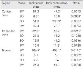
Table 1. Mechanical properties of the materials included in finite element analysis.
Young’s modulus (MPa)
Shear modulus (MPa)
Poisson’s ratio Cortical
bone
Ex 12,600 Gxy 4,850 Vxy 0.30 Ey 12,600 Gyz 5,700 Vyz 0.39 Ez 19,400 Gxz 5,700 Vxz 0.39 Trabecular
bone
Ex 1,150 Gxy 6,800 Vxy 0.001 Ey 2,100 Gyz 4,340 Vyz 0.32 Ez 1,150 Gxz 6,800 Vxz 0.05
Titanium 104,000 38,800 0.34
Cement 17,000 14,500 0.30
Acrylic resin 1,800 1,700 0.30
The subscripts x, y, and z correspond to the axis of the global coordinate system.
E = Young’s modulus, G = Shear modulus, V = Poisson’s ratio
Table 2. Peak tensile and compressive stresses (MPa) and maximum strain (µm) in the crestal cortical, trabecular, and api-cal cortiapi-cal bone measured under centric loading simulations.
Region Model Peak tensile stress
Peak compressive stress
Strain Cortical
bone
SW 87.2 44.3 0.0013
SO 8.8* 18.8 0.0004*
BO 51.3 233.9* 0.0037
BW 39.4 78.1 0.0024
Trabecular bone
SW 89.3* 66.7 0.2260*
SO 23.6 48.2 0.1220
BO 13.5 41.2 0.0346
BW 12.8 11.6* 0.0720
Titanium SW 106.9* 403.1* 0.0110*
SO 6.1 6.1 0.0002
BO 4.6 5.6 0.0002
BW 26.3 61.1 0.0018
engaged in the crestal cortical bone exhibit a biomechan-ical behavior different from that exhibited by implants placed at the crestal level. In the present study, engage-ment of the apex into the cortical bone decreased the displacement of subcrestal implants, albeit at the cost of higher stress in the bone around the implant apex.
Although there is no clinical evidence on the level of stress at which bone remodeling ceases and resorp-tion begins,20 the ultimate bone strength is assumed to be the physiological limit of the cortical bone.12 More-over, the peak compressive stress has been found to provide more reliable information in the analysis of bone resorption compared with the peak tensile stress.10 Therefore, bone resorption due to overloading should be expected when the compressive stress exceeds 100 to 130MPa in the cortical bone.21
In the present study, the implant placed at the crestal level (BO model) exerted a peak compressive stress of 233.9 MPa under centric loading, which is above the physiological limit for cortical bone tis-sue. This can explain the common clinical indings of crestal bone loss around the implant neck and the report of higher failure rates for implants placed in the posterior maxilla.19 All other models exhibited safer values of compressive stress under centric load-ing: 44.3, 18.8, and 78.1 MPa for the SW, SO, and BW models, respectively. However, under eccentric load-ing, only the SW and SO models presented safe val-ues. This decrease in compressive stress and strain in the crestal region can explain some clinical ind-ings of bone ingrowth coronal to the ixture–abut-ment interface6 and a higher success rate with an increase in the depth of placement.22
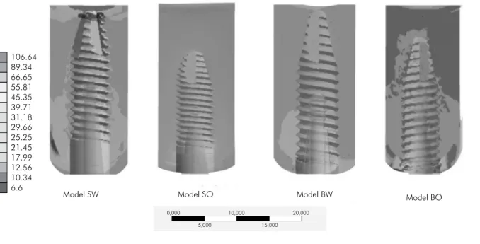
Figure 2. Compressive stress (MPa) around implants with different anchorage designs under centric loading.
0,000 10,000 20,000
15,000 5,000
106.64 89.34 66.65 55.81 45.35 39.71 31.18 29.66 25.25 21.45 17.99 12.56 10.34 6.6
Model SW Model SO Model BW Model BO
Table 3. Peak tensile and compressive stresses (MPa) and max-imum strain (µm) in the crestal cortical, trabecular, and apical cortical bone measured under eccentric loading simulations.
Region Model Peak tensile stress
Peak compressive
stress
Strain
Crestal cortical bone
SW 86.8 56.6 0.0045
SO 24.6* 34.1 0.0016*
BO 67.4 199.2* 0.0048
BW 66.6 127.4 0.0038
Trabecular bone
SW 85.2 65.6 0.2210*
SO 39.0 54.3 0.1460
BO 60.9 46.3 0.0750
BW 12.9* 17.6* 0.1079
Apical cortical bone
SW 124.2* 527.8* 0.0167*
SO 6.6 6.7 0.0026
BO 14.4 14.9 0.0005
BW 24.3 61.5 0.0014
This study was the irst, as per our knowledge, to evaluate apical cortical bone anchorage for sub-crestal implants. When the SW and SO models were compared, a shift in the stress and strain around the implant apex was evident in the SW model, conirm-ing that stresses are primarily dissipated through the cortical bone.21 This was most evident when the implants were subjected to eccentric loading, dur-ing which the higher compressive stress and strain around the implant apex can be a consequence of a greater lever arm due to the displacement of the ful-crum to the apical region.23 Moreover, the tapered
apex decreases the surface area available to dissipate the stress, explaining the high stress and strain in the apical region and highlighting the importance of macrodesign on stress distribution around imme-diately loaded implants.17 This may not be critical because the resistance to fatigue failure in the cor-tical bone is greater during compression than dur-ing tension.24 Deposition and resorption of the bone matrix can be regulated by the mechanical
environ-ment;25 therefore, possible remodeling of the cortical
bone around the implant apex should be assessed in future in vivo studies or clinical trials.
With regard to tensile stress, however, the SW model showed higher values in all bone regions compared with the other models. It was previously shown that tensile stress can induce ossiication by increasing the expression of bone morphogenetic protein (BMP)-2 and BMP-4, which are bone growth factors.25 Therefore, this residual tensile stress can also explain why there is bone formation above the implant platform when the implants are placed subcrestally.6 On the other hand, this can be the consequence of the assumption that
cortical and trabecular bones are homogeneous and
perfectly bonded in the analysis because the implant platform is only 1 mm away from the trabecular/cor-tical interface. Because there is no threshold value to stimulate bone apposition, and because excessive ten-Figure 4. Vertical and horizontal implant displacement (µm)
during centric and eccentric loading simulations.
Implant Displacement (µm)
35
30
25
20
15
10
5
0
SW SO BO BW SW SO BO BW
Eccentric loading Centric loading
Vertical Horizontal
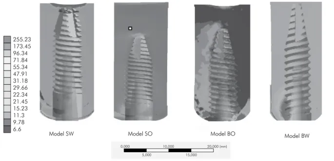
Figure 3. Compressive stress (MPa) around implants with different anchorage designs under eccentric loading.
0,000 10,000 20,000 (mm)
15,000 5,000
255.23 173.45 96.34 71.84 55.34 47.91 31.18 29.66 22.34 21.45 15.23 11.3 9.78 6.6
sile stress reportedly causes bone resorption,26 load -ing forces should be controlled by careful occlusal adjustments to avoid bone resorption.
Both subcrestal models were more eficient in decreasing the strain in the crestal region compared with the model with bicortical ixation. However,
the strain generated was above the value considered
risky for bone fracture; furthermore, it is dificult to estimate cellular and tissue responses to different levels of strain.27 Moreover, the subcrestal implant positioned only in the trabecular bone produced the lowest stress and strain in all evaluated regions. The low elastic modulus of trabecular bone acts as a stress breaker that promotes better dissipation of stresses from the occlusal loading.28
However, the peak stress was substituted by higher implant displacement. In the present study, all models exhibited implant displacement below the threshold of 150 µm required to prevent ibrous tissue formation;2 these are in the same range reported by a previous study using FEA.29 However, previous in vitro studies reported displacement values of 100 to 340 μm in type IV bone samples,30 which were above the stated threshold.
The limitation of the present study was that the trabecular bone was considered to be a uniform and homogeneous material. It is important to consider the morphology and density of the trabeculae in tra-becular bone to determine its biomechanical inlu-ence on subcrestal implants. Future studies should evaluate the effects of possible remodeling around the apex on the success of subcrestal implants.
Conclusions
Subcrestal implant placement decreases the stress in the crestal cortical bone around dental implants, regard-less of apical anchorage; however, apical cortical anchor-age can be effective in limiting implant displacement.
Acknowledgments
This study was supported by Fundação de Amparo à Pesquisa do Estado de São Paulo (FAPESP no. 2011/22231-9) and the Conselho Nacional de Desenvolvimento Cientí-ico e TecnológCientí-ico (CNPq no. 159946/2011-5). The authors give a special thanks to Dr. Carlos Murgel (Campinas, Brazil) for providing the tomographic images.
References
1. Javed F, Romanos GE. The role of primary stability for suc-cessful immediate loading of dental implants. A literature review. J Dent. 2010 Aug;38(8):612-20.
2. Szmukler-Moncler S, Salama H, Reingewirtz Y, Dubruille JH. Timing of loading and effect of micromotion on bone-dental implant interface: review of experimental literature. J Biomed Mater Res. 1998 Summer;43(2):192-203.
3. Devlin H, Horner K, Ledgerton D. A comparison of maxil-lary and mandibular bone mineral densities. J Prosthet Dent. 1998 Mar;79(3):323-7.
4. Tran BL, Chen ST, Caiafa A, Davies HM, Darby IB. Trans-mucosal healing around peri-implant defects: crestal and subcrestal implant placement in dogs. Clin Oral Implants Res. 2010 Aug;21(8):794-803.
5. Hammerle CH, Bragger U, Burgin W, Lang NP. The effect of subcrestal placement of the polished surface of ITI implants on marginal soft and hard tissues. Clin Oral Implants Res. 1996 Jun;7(2):111-9.
6. Donovan R, Fetner A, Koutouzis T, Lundgren T. Crestal bone changes around implants with reduced abutment diameter placed non-submerged and at subcrestal positions: a 1-year radiographic evaluation. J Periodontol. 2010 Mar;81(3):428-34.
7. Barros RR, Novaes Jr. AB, Muglia VA, Lezzi G, Piattelli A. Influence of interimplant distances and placement depth on peri-implant bone remodeling of adjacent and immediately loaded morse cone connection implants: a histomorphometric study in dogs. Clin Oral Implants Res. 2010 Apr 1;21(4):371-8.
8. Huang B, Meng H, Piao M, Xu L, Zhang L, Zhu W. Influence of placement depth on bone remodeling around tapered in-ternal connection implant: a clinical and radiographic study in dogs. J Periodontol. 2012 Sep;83(9):1164-71.
9. Canullo L, Pace F, Coelho P, Sciubba E, Vozza I. The influence of platform switching on the biomechanical aspects of the im-plant-abutment system. A three dimensional finite element study. Med Oral Patol Oral Cir Bucal. 2011 Sep;16(6):e852-6. 10. Huang CC, Lan TH, Lee HE, Wang CH. The
biomechani-cal analysis of relative position between implant and al-veolar bone: finite element method. J Periodontol. 2011 Mar;82(3):489-96.
12. Baggi L, Cappelloni I, Di Girolamo M, Maceri F, Vairo G. The influence of implant diameter and length on stress distribution of osseointegrated implants related to crestal bone geometry: a three-dimensional finite element analysis. J Prosthet Dent. 2008 Dec;100(6):422-31.
13. Ahn SJ, Leesungbok R, Lee SW, Heo YK, Kang KL. Differ-ences in implant stability associated with various methods of preparation of the implant bed: an in vitro study. J Prosthet Dent. 2012 Jun;107(6):366-72.
14. Katranji A, Misch K, Wang HL. Cortical bone thickness in dentate and edentulous human cadavers. J Periodontol. 2007 May;78(5):874-8.
15. Ausiello P, Apicella A, Davidson CL. Effect of adhesive layer properties on stress distribution in composite restorations--a 3D finite element analysis. Dent Mater. 2002 Jun;18(4):295-303. 16. Sevimay M, Turhan F, Kilicarslan MA, Eskitascioglu G.
Three-dimensional finite element analysis of the effect of different bone quality on stress distribution in an implant-supported crown. J Prosthet Dent. 2005 Mar;93(3):227-34. 17. Huang HL, Hsu JT, Fuh LJ, Lin DJ, Chen MY. Biomechanical
simulation of various surface roughnesses and geometric designs on an immediately loaded dental implant. Comput Biol Med. 2010 May;40(5):525-32.
18. Hattori Y, Satoh C, Kunieda T, Endoh R, Hisamatsu H, Wata-nabe M. Bite forces and their resultants during forceful intercus-pal clenching in humans. J Biomech. 2009 Jul 22;42(10):1533-8. 19. Clelland NL, Lee JK, Bimbenet OC, Gilat A. Use of an
axisym-metric finite element method to compare maxillary bone vari-ables for a loaded implant. J Prosthodont. 1993 Sep;2(3):183-9. 20. Frost HM. A 2003 update of bone physiology and Wolff’s law
for clinicians. Angle Orthod. 2004 Feb;74(1):3-15.
21. Natali AN, Hart RT, Pavan PG, Knets I. Mechanics of bone tissue. In: Natali AN, editor. Dental biomechanics. London: Taylor & Francis; 2003. p. 1-19.
22. Lee EH, Ryu SM, Kim JY, Cho BO, Lee YC, Park YJ, et al. Effects of installation depth on survival of an hydroxyapa-tite-coated bicon implant for single-tooth restoration. J Oral Maxillofac Surg. 2010 Jun;68(6):1345-52.
23. Weinberg LA. Reduction of implant loading using a modi-fied centric occlusal anatomy. Int J Prosthodont. 1998 Jan-Feb;11(1):55-69.
24. Carter DR, Caler WE, Spengler DM, Frankel VH. Fatigue behavior of adult cortical bone: the influence of mean strain and strain range. Acta Orthop Scand. 1981 Oct;52(5):481-90. 25. Sato M, Ochi T, Nakase T, Hirota S, Kitamura Y, Nomura S,
et al. Mechanical tension-stress induces expression of bone morphogenetic protein (BMP)-2 and BMP-4, but not BMP-6, BMP-7, and GDF-5 mRNA, during distraction osteogenesis. J Bone Miner Res. 1999 Jul;14(7):1084-95.
26. Carter DR. Mechanical loading histories and cortical bone remodeling. Calcif Tissue Int. 1984;36 Suppl 1:S19-24. 27. Frost HM. The role of changes in mechanical usage set points
in the pathogenesis of osteoporosis. J Bone Miner Res. 1992 Mar;7(3):253-61.
28. Morris HF, Ochi S, Crum P, Orenstein IH, Winkler S. AICRG, Part I: a 6-year multicentered, multidisciplinary clinical study of a new and innovative implant design. J Oral Im-plantol. 2004 Jun;30(3):125-33.
29. Chang PK, Chen YC, Huang CC, Lu WH, Chen YC, Tsai HH. Distribution of micromotion in implants and alveolar bone with different thread profiles in immediate loading: a finite element study. Int J Oral Maxillofac Implants. 2012 Nov-Dec;27(6):e96-101.