POWER SYSTEM REACTIVE COMPENSATION: EVALUATION OF
EXPANSION PLANS TAKING INTO ACCOUNT ELECTROMAGNETIC
TRANSIENT RESTRICTIONS
Fabrício Silveira Chaves
∗Maria Helena Murta Vale
∗∗LRC - Lightning Research Center / UFMG
Antônio Carlos Avenue 6627 - Pampulha CEP 31.270-901 - Belo Horizonte - MG - Brazil
RESUMO
Neste artigo, os autores apresentam seus desenvolvimentos atuais sobre Compensação Reativa Shunt Capacitiva e Con-trole de Tensão, no contexto do Planejamento da Expansão, considerando estudos de transitórios eletromagnéticos. O montante e localização da compensação reativa a ser insta-lada na rede elétrica é definido considerando muitos aspec-tos como otimização da potência reativa, cálculos de curto-circuito, estabilidade de tensão, análises de harmônicos, en-tre outros. Diferentes alternativas devem ser avaliadas, con-siderando seus impactos (positivos e negativos) no compor-tamento do sistema, a fim de selecionar a compensação mais adequada. O processo de decisão da expansão normalmente não inclui estudos sobre o impacto dos transitórios eletro-magnéticos causados pelo chaveamento da compensação re-ativa shunt. Tradicionalmente, isto é feito somente depois da definição do plano de expansão, ao se elaborar o projeto deta-lhado – fase em que se especificam os equipamentos a serem utilizados. Neste artigo, é proposto um procedimento novo que inclui uma avaliação técnica de diferentes compensações
shunt baseado numa verificação prévia dos valores de
sobre-tensão e sobrecorrente causados pelo chaveamento de bancos de capacitores. A nova metodologia é dividida em dois prin-cipais passos: (i) indicar as barras críticas do sistema que de-vem ser investigadas detalhadamente, considerando o com-portamento transitório; e (ii) escolher a compensação shunt
Artigo submetido em 01/02/2008 (Id:856) Revisado em 01/09/2008 e em 14/11/2008
Aceito sob recomendação do Ed.Assoc. Prof. Julio Cesar Stacchini Souza
mais adequada. O procedimento proposto é explicado com detalhes e são apresentados os resultados de sua aplicação em um sistema real.
PALAVRAS-CHAVE: Compensação Reativa Shunt Capaci-tiva, Controle de Tensão, Transitórios Eletromagnéticos, Avaliação Técnica, Chaveamento de Capacitores.
ABSTRACT
(i) indicate the critical system buses that must be carefully investigated, considering transient behavior, and (ii) promote the adequate shunt compensation adjust. The proposed pro-cedure is detailed and results of its application in real systems are presented.
KEYWORDS: Capacitive Shunt Reactive Compensation, Voltage Control, Electromagnetic Transients, Technical Evaluation, Capacitor Switching.
1
INTRODUCTION
Power System Planning activities involve the analysis of sev-eral and different expansion alternatives. Capacitive Shunt Reactive Compensation (RC) appears as one of the most adopted due to its relevant benefits for system behavior. Op-timization of reactive power flow, voltage control, reduction of system losses and power factor adjustment are some of these benefits. Besides, reactive compensation is very attrac-tive regarding economic aspects.
Traditionally, planners staff identifies the amount and loca-tion of RC equipment based on reactive power flow and in-jection optimization. Several system conditions are investi-gated considering different operative states (normal, restora-tive and emergency), in order to decide about the RC to be adopted.
The optimal power flow calculation has been the basic tool used to prepare expansion plans. The formulation involves the selection of specific objective functions and restrictions to be obeyed. A greater and better exploitation of system re-sources is expected considering cost minimization. Regard-ing reactive compensation, objective functions commonly used refers to the minimization of the reactive power flow in system network, the reactive power injection to be installed, the reactive and active losses, and the costs of acquisition, maintenance and operation of the equipment to be placed. Such objectives must be reached without violating technical, economic, security, legislation, social and ambient restric-tions. The RC plan must provide an adequate voltage con-trol. This optimization process has been explored by the au-thors as described in Chaves (2001) and in Chaves and Vale (2002).
The consideration of all aspects mentioned above character-izes a complex problem to be solved by planners. In fact, the decision process involves specific procedures that guide plans preparation. The methodology developed and adopted by the authors considers the following steps: (i) Power Sys-tem Diagnosis Evaluation, in order to detect any deficiency; (ii) RC Equipment Definition – one or more alternatives are usually generated by some optimization process; (iii) Eco-nomical and Technical Evaluation of the alternatives; (iv)
Selection of the most adequate alternative and Preparation of the Expansion Plan to be adopted. It is important to em-phasize that these steps indicate the RC amount and location. After them, project activities take place, where all equipment are specified in details.
All steps of the decision process identified above are treated in details by the authors in reference Chaves (2007). The optimization process proposed in this reference, step (ii), has been successfuly applied in real system planning strategies, to identify RC alternatives (Chaves and Vale, 2002). The relevance of the technical evaluation step (iii) is emphasized, because it is responsible for the analysis of the influence of the suggested RC equipment in system behavior. Depending on the results of these analyses, the planning RC proposals may be adjusted or even neglected.
In addition to the commonly studies prepared in this stage, the authors developed special procedures to evaluate the im-pact of shunt compensation on system voltage stability (Vale, 2005), harmonic distortion and electromagnetic transients. The present work is dedicated to the electromagnetic stud-ies.
As known, shunt capacitors switching can result in signif-icant overvoltage and overcurrent in power systems. De-pending on the magnitudes of these transients and on sys-tem damping, the capacitor bank and other equipment in its vicinity can be damaged (Coury et alii, 1998; McGranaghan et alii, 1992; Surge Protective Devices Committee, 1996). To avoid these problems, electromagnetic transient analyses are usually done during equipment specification task when circuit breakers and other switching equipment are chosen. So, electromagnetic studies are prepared only after RC is already defined. In this paper, it is suggested these studies to be started in a very previous stage, in the evaluation step of expansion plans preparation. This procedure allows the selection of a better alternative in terms of transient impact on power system behavior. In conjunction with the detailed analysis prepared during substation project, it is expected that the final specified RC presents technical and economi-cal advantages.
The short circuit calculations normally prepared in step (iii) simply verify if the RC reactive power is smaller than 5% of the system short circuit power. A relevant aspect to be noted is that this calculation does not guarantee that overvoltage and overcurrent values caused by capacitors bank switching are inferior to maximum permitted limit. This is shown in item 4.
a trivial task, mainly in large systems. The complexity of this subject and the lack of planning strategies that include switching overvoltage and overcurrent analysis motivate the investigation reported in this work.
2
CRITICAL BUSES RELATED TO
ELEC-TROMAGNETIC TRANSIENTS
In order to evaluate different RC alternatives regarding tran-sient effects, many simulations must be prepared consider-ing the capacitors switchconsider-ing possibilities (energization and de-energization). In large power systems, the evaluation of several network configurations constitutes a very laborious and time-consuming task, sometimes making the study im-practicable. Additionally, the analysis of all the cases would include unnecessary simulation.
In this work, a technique that identifies the so-called "crit-ical buses" is proposed. Such identification allows know-ing which bus has the highest overvoltage or overcurrent in the energization or de-energization of a specific capacitor bank. The technique is used to classify the buses in accor-dance with system configuration: size of the switched capac-itor, load characteristics, electrical distance of the source, in-stalled equipment and other aspects (Coury et alii, 1998; Jota and Islan, 1998; McGranaghan et alii, 1992; Saied, 2004; Surge Protective Devices Committee, 1996).
The proposed method is based on the determination of in-dices that consider the coefficients of reflection (RF L)and
refraction (RF R)of the system, as Greenwood (1991). In
this paper, the methodology is applied only to identify the critical buses in terms of overvoltage aspect.
The analysis is made in a local form, considering the system as simple as possible, in such a way that the calculated in-dices give a notion of the overvoltage caused by transients. To compute these indices, voltage source is considered an unitary step, adopting short spaces of time.
With the objective of exemplify the proposed process, the simple circuit of 5 buses and 4 branches, illustrated in Figure 1, is adopted. Resistive loads have been considered, in order to simplify the analysis of the reflection and refraction coef-ficients. The respective values for the impedances Z1, Z2, Z3 and Z4(ohm) are 1.0, 2.0, 1.5 and 0.5, respectively. Propa-gation time (τ)has been assumed as 1µs for Z1impedance line and 5µs for the other ones.
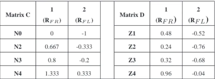
The analysis involves two coefficient matrices (C, D), dimen-sion (4x2), as seen in table 1, where overvoltage values are related to the example system. In matrix C, the coefficients of points N0 (source), N2, N3and N4 (loads) are inserted. In matrix D, coefficients related to point N1are placed in this
Figure 1: Circuit for coefficients RFL e RFR study.
way: the value calculated for each impedance (Z1, Z2, Z3, Z4)considers the equivalent as viewed from each one. The source is considered a short circuit whereas its internal re-actance is admitted null. In these matrices, the first column represents the refraction coefficients and the second column contains the reflection coefficients.
Table 1: Refraction and reflection coefficients for the system of Figure 1.
Matrix C 1 (RF R)
2 (RF L)
Matrix D 1 (RF R)
2 (RF L)
N0 0 -1 Z1 0.48 -0.52
N2 0.667 -0.333 Z2 0.24 -0.76
N3 0.8 -0.2 Z3 0.32 -0.68
N4 1.333 0.333 Z4 0.96 -0.04
The overvoltage value depends on the coefficients just calcu-lated and on the wave propagation time. This time has been neglected by the proposed methodology. The consideration of all reflections (or propagation time) in each point of the circuit would result in extremely complex calculations, sim-ilar to the complete transient simulation for all buses. More-over, in fact, its consideration would not introduce great dif-ference in index value, because a small parcel of the original wave would be added to each reflection.
The suggested index (Citotal)consists of the sum of the
fol-lowing terms: first refracted wave in the load (FRL),
re-flected wave in point N1 (FLN1), reflected wave in source (FLS)and refracted wave by the loads in point N1 (FRN1) (equation (1)). The biggest value of index (Citotal)indicates
v:N0
v:N1
v:N2
v:N3
v:N4
0 10 20 30 40 50 60 70 [us] 80
0.0 0.3 0.6 0.9 1.2 1.5 [V]
N4
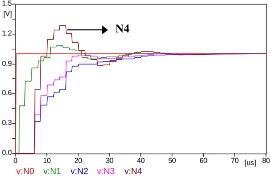
Figure 2: Voltage values in each point of Figure 1 circuit.
Ci total=F RL+F LN1+F LS+F RN1 (1)
FRLis composed by the wave that comes from source,
sur-passes point N1(d11)and refracts in the load (ci1). FLN1is a wave FRLthat reflects in load (ci2), later in point N1(di2) and refracts in load (ci1). FLSis the wave that does not cross
point N1(d12), reflects in source (c12)and, after that, goes beyond point N1(d11)and refracts in load (ci1). FRN1is the wave that, after reflecting in other loads (cj2), it passes point N1in direction to the desired load (dj1)and refracts in this load (ci1). The i and j pointers of the coefficient matrices C and D are always greater than 1. The goal becomes to ver-ify Citotal in loads. Equation (2), derived from equation (1),
explains what is dealt with in this paragraph.
Ci total=
1 +ci2·di2+d12·c12+
n
X
j6=i
cj2·dj1
·d11·ci1
(2)
To validate this index, several tests are prepared. Consider-ing the example system, the obtained indices for points N2, N3and N4 are, respectively, 0.65, 0.73 and 0.87. Point N4 reaches the highest overvoltage (Figure 2) and the maximum index value, so confirming the critical bus detection.
3
ELECTROMAGNETIC TRANSIENTS
-EVALUATION OF REACTIVE
COMPEN-SATION PLAN
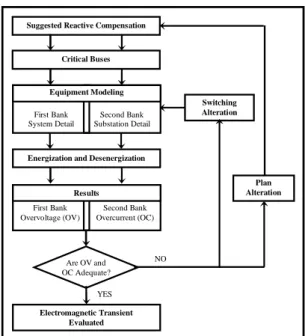
The proposed procedure for technical evaluation of RC alter-natives, in terms of electromagnetic transient aspects, con-sists of distinct analyses: energization and de-energization of the first and second capacitor banks. The procedure steps, described below, and the flowchart of this evaluation are pre-sented in Figure 3.
i. Suggested Reactive Compensation
This step is related to the procedure input data, which inform about the RC alternative to be evaluated.
ii. Critical Buses
The critical bus has the highest index Citotal, as
ex-plained in item 2. In this step, the buses that have the highest overvoltage and overcurrent are identified and, for them, simulations are made.
iii. Equipment Modeling
Suggested Reactive Compensation
Are OV and OC Adequate? Critical Buses
Electromagnetic Transient Evaluated Energization and Desenergization
NO
Plan Alteration
YES
Switching Alteration Second Bank
Substation Detail First Bank
System Detail Equipment Modeling
Second Bank Overcurrent (OC) First Bank
Overvoltage (OV) Results
Figure 3: Expansion Technical Evaluation – Electromagnetic Transient.
(a) Analysis 1 – First Bank
The main goal of this analysis is to evaluate the overvoltage caused by a single bank switching, placed in a bus. The simulation considers three adjacent buses to this bank.
(b) Analysis 2 – Second Bank
This analysis evaluates the overcurrent caused by the second bank switching (back-to-back config-uration). The substation, where the capacitor is located, is modeled in this study. Equivalents are prepared to represent other system equipment.
iv. Energization and De-energization
In this step, simulations are realized considering en-ergization and de-enen-ergization of the first and second banks. Adopting the adequate circuit modeling for each analysis, overvoltage and overcurrent resultant from ca-pacitor switching are determined. Measurements are prepared for the capacitor, load and near sensible equip-ment. Energy absorbed by the surge arrester is also mea-sured. In the de-energization analysis, breaker restrike is considered (Das, 2005; Grebe and Gunther, 1998; McGranaghan et alii, 1992). An electromagnetic tran-sient software may be used for simulations.
v. Results
Reports and graphs are generated to present overvoltage values (OV) related to first bank simulations and over-current values (OC) to the second.
vi. Are OVand OC adequate?
OV and OC must be inferior to the maximum value sup-ported by the equipment near capacitor (Sabin et alii, 1999). It must be verified if the surge arrester supports the produced energy at the moment capacitor switching occurs, in order to avoid the risk of this equipment to burn or to open the circuit (Grebe and Gunther, 1998; McGranaghan et alii, 1992). It is also evaluated if the capacitor switching can make unused some circuit ele-ment or cause any alteration in the normal operation of sensible equipment. Such limits depend on the installed equipment and the number of capacitor switchings real-ized during the year.
vii. Plan Alteration
If some restriction is not respected, it is necessary to modify the suggested RC expansion plan. The proce-dure that indicates the adequate modifications considers the evaluation of different options:
(a) Alteration of the number of capacitors, without
modifying the amount of reactive power placed in the bus. Different load conditions (light, average and heavy) are considered in simulations.
(b) Substitution of the initially proposed capacitor by
another equipment with more adequate switching behavior.
(c) Selection of one or more buses to have their
reac-tive compensation modified or eliminated. To se-lect these buses, a sensitivity analysis is used to identify the so-called “candidate bus”. The can-didate bus is the one that has more influence over the critical bus (detected by transient simulations), regarding voltage control and reactive compensa-tion. The amount of reactive power is partially or integrally transferred from the critical bus to the candidate one.
In this process, it is very important to consider Citotal
values, to avoid choosing a bus that is inadequate re-garding transient aspects. Reactive power must be dislo-cated towards buses with smaller indices Citotalto
pre-vent overvoltage and overcurrent increases.
viii. Switching Type Alteration
4
SIMULATION RESULTS
The selected power system is a real network of 19 buses and ATPDraw, a commercial program, is used for electromag-netic transient calculations.
Before showing results related to the use of transient analy-ses to decide about adequate RC definition, it is interesting to discuss about the short circuit criterion mentioned in item 1. Table 2 presents some simulation results showing that this criterion does not guarantee overvoltage values, caused by capacitors bank switching, to be inferior to maximum per-mitted limit. In this table, “RCmax” indicates the maximum Mvar values according to short circuit evaluation (5% of sys-tem short circuit power). “RC” contains the Mvar values pro-posed by the optimization process and “OV RC” shows the overvoltages for each bus. One can see that, even inferior than those pointed by short circuit criterion, the proposed “RC” may not attend transient limits (1.80 pu, in this ex-ample). This fact emphasizes the importance of including transient analyses in planning evaluating step (iii).
Table 2: Reactive compensation and overvoltage values.
RCmax (Mvar)
RC (Mvar)
OV RC (pu)
18.9 6.2 1.89
27.7 0.5 1.84
25.2 24.2 1.77
27.0 17.5 1.85
The optimization process suggests the initial shunt
compen-sation. For the 13.8 kV buses, it indicates the use of 2.4 and 4.8 Mvar capacitors. Three buses with very distinct charac-teristics are chosen to identify the critical bus. Their loads are 16.6 MVA, 20 MVA and 71.2 MVA. Two capacitors of 4.8 Mvar are proposed for the first bus, a 2.4 Mvar capaci-tor for the second and a 4,8 Mvar capacicapaci-tor for the last one. There is an additional 75.4 MVA load near the second bus. The lines that supply energy for these loads are 50km, 100km and 200km in length, respectively.
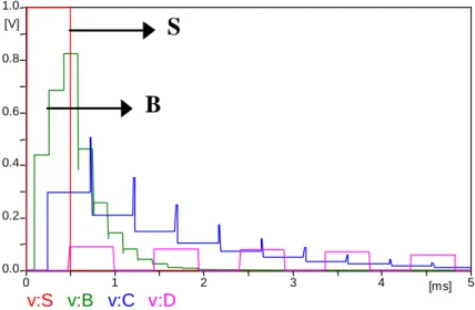
The calculated overvoltage indices (Citotal) of the three
buses are 1.61, 1.46 and 1.26. The critical bus is the first one that has the biggest index and light load. Figure 4 presents the voltage values of the simplified system composed by these buses. It is confirmed that the biggest overvoltage oc-curs in bus 1, represented by letter B. Letter S represents the voltage in the source. The critical bus, in terms of overcur-rent, coincidentally is the same bus.
For the first capacitor bank, system is modeled in a macro way (system level – adjacent buses are considered):
- Source model: equivalent voltage source (Vth);
- Transmission line model: transposed three-phase line; zero
and positive sequence data; line length;
- Load model: three-phase linear element; resistive and
in-ductive components;
- Capacitor model: three-phase linear element; capacitive
parameter;
- Circuit breaker model: simultaneous three-phase
switch-ing in the peak value of one of the phases (simple model);
v:S
v:B
v:C
v:D
0 1 2 3 4 [ms] 5
0.0 0.2 0.4 0.6 0.8 1.0
[V]
B
S
- Transformer model: three-phase two-winding saturated
transformer; wye-delta connection with grounded neu-tral.
For the second bank, system is modeled in a micro way (sub-station level):
- Source model: equivalent voltage source (Vth);
- Transmission line model: equivalent three-phase line;
- Load model: three-phase linear element; resistive and
in-ductive components;
- Capacitor model: three-phase linear element; resistive and
capacitive components;
- Circuit breaker model: simultaneous three-phase
switch-ing in the peak value of one of the phases (simple model);
- Busbar and conductor model: three-phase linear element;
resistive and inductive components;
- Transformer model: three-phase two-winding saturated
transformer; wye-delta connection with grounded neu-tral.
Energization and de-energization of the first and second banks are completely simulated but, in the present paper, it is shown only energization results and the respective plan al-teration.
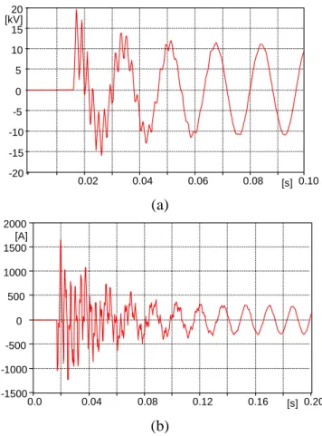
The first bank energization (4.8 Mvar) generates an overvolt-age of 1.86 pu that can be confirmed by the graph depicted in Figure 5 (a). Transient remains approximately by 61 ms. Considering that capacitor switching is realized 400 times per year, the voltage limit to be adopted for the capacitor is 1.80 pu by 50 ms. Therefore, the expansion plan alteration becomes necessary.
In the second 4.8 Mvar bank, the overcurrent is 5.72 pu (Fig-ure 5 (b)) and the transient remains approximately by 180 ms. It is adopted a typical limit of 4.0 pu during 1 s. Then, it becomes necessary to modify the plan.
An option for planning modification would be to maintain the Mvar amount and localization suggested by the steady state optimization process, but changing the number of capacitors placed in the critical bus.
This procedure is done for the case study, using a 9.6 Mvar capacitor instead of two of 4.8 Mvar. In this new configura-tion, the system presents a lower overcurrent, due to the fact that it is not necessary to energize the second bank. However,
(a)
(b)
0.02 0.04 0.06 0.08 [s] 0.10
-20 -15 -10 -5 0 5 10 15 20 [kV]
0.0 0.04 0.08 0.12 0.16 [s] 0.20
-1500 -1000 -500 0 500 1000 1500 2000 [A]
Figure 5: (a) Voltage transient in energization of first bank; (b) overcurrent transient in energization of second bank.
the overvoltage increases to 1.89 pu during 89 ms, denoting that problem is not solved.
Another option is to indicate, by a sensitive analysis, a candi-date bus to receive partially or totally the compensation. This bus is that with the heaviest load and lowest transient index. In the case study, it is added 8.4 Mvar in the candidate bus, remaining only 1.2 Mvar in the critical bus. Here, again, it is not necessary to energize the second bank. The critical bus overvoltage diminishes to 1.75 pu, remaining by 69 ms, and the candidate bus overvoltage reaches 1.55 pu by a period of 25ms. Both overvoltages are within the limit considered acceptable.
(a)
(b)
0.0 0.02 0.04 0.06 0.08 [s] 0.10
-15 -10 -5 0 5 10 15 [kV]
0.02 0.04 0.06 0.08 [s] 0.10
-15 -10 -5
0 5 10 15 20 [kV]
0.0
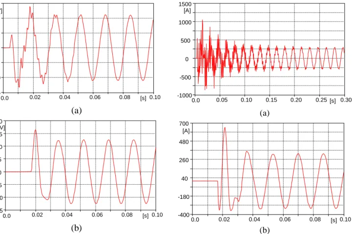
Figure 6: Overvoltage transient in the first bank energization (a) with synchronized switching; (b) with preinsertion reactor.
With the switching type modifications, the overvoltage and overcurrent limits are respected and their magnitudes are smaller than those obtained with compensation change pro-cedure. Nevertheless, additional cost and insertion of electric losses are expected. The planner must ponder over the possi-bilities, considering electrical and economic aspects, in order to choose the most appropriate solution.
The example treated in this paper dealt with only the switched capacitor limits. However, the restrictions could be related to an equipment installed near the compensation or to a surge arrester that could not support the transient en-ergy, burning or opening the circuit. For these cases, the pro-cedure for expansion planning alteration follows the same steps, modifying only the limit to be observed.
5
CONCLUSIONS
This work presents a strategy to prepare the technical eval-uation of expansion alternatives for reactive compensation in the aspects of electromagnetic transient. The importance to verify the overvoltage and overcurrent originated from
(a)
(b)
0.0 0.05 0.10 0.15 0.20 0.25[s] 0.30
-1000 -500 0 500 1000 1500 [A]
0.0 0.02 0.04 0.06 0.08 [s] 0.10
-400 -180 40 260 480 700 [A]
Figure 7: Overcurrent transient in the second bank energiza-tion (a) with synchronized switching; (b) with preinserenergiza-tion re-actor.
capacitor switching is confirmed by the obtained results. Capacitor transients can provoke irreparable damages into equipment and deteriorate system performance. A previous and careful analysis prepared during planning stage, not only during equipment final specification, can avoid serious criti-cal situations to power systems.
If the planning evaluation step points out that the suggested RC alternative is not satisfactory, it must be modified. The RC plan alteration can be done by changing the amount and localization of the capacitive compensation or by modifying the capacitor switching type. Each option has its proper-ties, remaining to the planner the selection of the most ad-equate one. In very specific cases such modifications are not viable and another expansion alternative (new transmission line, substations and others) should be investigated.
classification that indicate those with high overvoltage and overcurrent. By the obtained results, it is confirmed that the application of these indices is valid and important for reactive compensation choice.
REFERENCES
Bhargava, B., A.H. Khan, A.F. Imece, and J. Di Pietro (1993). Effectiveness Of Pre-Insertion Inductors For Mitigating Remote Overvoltages due To Shunt Capac-itor Energization. IEEE Transactions on Power
Deliv-ery, Vol. 8, No. 3, pp. 1226-1238.
Chaves, F.S. (2001). Technical Procedure Applied to Re-active Compensation and Voltage Control in Electric Power Systems (in Portuguese). MSc. Dissertation, Su-pervisor: M.H.M. Vale, LRC/PPGEE – Federal Univer-sity of Minas Gerais, Brazil.
Chaves, F.S. and M.H.M. Vale (2002). Voltage Control and Reactive Compensation – Technical Procedure Applied to Power System Expansion (in Portuguese). XIV CBA, Natal – Brazil.
Chaves, F.S. (2007). Technical Evaluation of the Capaci-tive Shunt ReacCapaci-tive Compensation Performance Ap-plied to Electric Power System Expansion (in Por-tuguese). Ph.D. Dissertation, Supervisor: M.H.M. Vale, LRC/PPGEE – Federal University of Minas Gerais, Brazil.
Coury, D.V., C.J. Santos and M.C. Tavares (1998). Transient Analysis Resulting from Shunt Capacitor Switching in an Actual Electrical Distribution System.8th
Interna-tional Conference on Harmonics and Quality of Power ICHQP’98 (IEEE), Athens – Greece, pp. 292-297.
D’Ajuz, A., C.S. Fonseca, F.M.S. Carvalho, J. Amom Filho, L.E.N. Dias, M.P. Pereira, P.C.V. Esmeraldo, R. Vais-man, and S.O. Frontin (1987). Electric Transients and
Insulation Coordination – Application in High-voltage Power Systems (in Portuguese). Fluminense Federal
University, Rio de Janeiro – Brazil.
Das, J.C. (2005). Analysis and Control of Large-Shunt-Capacitor-Bank Switching Transients. IEEE
Transac-tions on Industry ApplicaTransac-tions, Vol. 41, No. 6, pp.
1444-1451.
Fernandez, P.C., P.C.V. Esmeraldo, J. Amom Filho, and C.R. Zani, (2004). Use of Controlled Switching Systems in Power System to Mitigate Switching Transients. Ex-perience Trends And Benefits – Brazilian. IEEE/PES
Transmission & Distribution Conference & Exposition: Latin America, pp. 85-90.
Grebe, T.E. and E.W. Gunther (1998). Application of the EMTP for Analysis of Utility Capacitor Switching Mitigation Techniques.8thInternational Conference on
Harmonics and Quality of Power ICHQP’98 (IEEE),
Atenas – Greece, pp. 583-589.
Greenwood, A. (1991). Electrical Transients in Power
Sys-tems, 2ndEdition, John Wiley & Sons, Inc..
Jota, P.R.S. and S.M. Islam (1998). Effect of Realistic Sys-tem Modelling on Low-Voltage Capacitor Transient Overvoltages. IEE Proceedings Generation,
Transmis-sion & Distribution, Vol. 145, No. 6, pp. 682-686.
McGranaghan, M.F., R.M. Zavadil, G. Hensley, T. Singh, and M. Samotyj (1992). Impact of Utility Switched Ca-pacitors on Customer Systems – Magnification at Low Voltage Capacitors. IEEE Transactions on Power
De-livery, Vol. 7, No. 2, pp. 862-868.
Sabin, D.D., T.E. Grebe, D.L. Brooks, and A. Sundaram (1999). Rules-Based Algorithm for Detecting Transient Overvoltages due to Capacitor Switching and Statistical Analysis of Capacitor Switching in Distribution Sys-tems. IEEE, pp. 630-635.
Saied, M. (2004). Analysis of the Amplitude and Frequen-cies of the Voltage Magnification Transients in Distri-bution Networks due to Capacitor Switching.
IEEW-PES Transmission CL Distribution Conference & Ex-position: Latin America, pp. 34-38.
Surge Protective Devices Committee (1996). Impact of Shunt Capacitor Banks on Substation Surge Environment and Surge Arrester Applications. Report by Working Group
3.4.17 of the IEEE Transactions on Power Delivery,
Vol. 11, No. 4, pp. 1798-1809.