Abstract
According to the research fruits of the diverse damages of bridge in the past, bearings' invalidation is the main reason of the dam-age of isolated bridges and causes oversized relative displacements between pier and girder. Eventually, it may lead to severe collision of superstructure. It is extremely dangerous when near-fault mo-tion occurs, because it has obvious velocity pulse effect and in-creases the risk of colliding between girders.
Aiming at this problem, this paper puts forward a device named cable-sliding modular expansion joints (CMEJs) that can control the relative displacement and avoid collision. The working princi-ple and mechanical model are described, and then based on a triple continuous seismic isolation bridge which has different heights of piers, a 3D model with or without CMEJs is estab-lished. The responses of continuous beam bridges using the CMEJs are comprehensively inspected under the consideration of the velocity pulse effect, and then a real simulation of limit per-formance of CMEJs is made, focused on CMEJs' restraining effect. The calculation shows that velocity pulse effect would magnify the seismic response of isolation bridges. In addition, the device can well control the displacement and prevent collisions. And the isolation technology combined with CMEJs can be more effective to play their respective roles. The advantage in controlling dis-placement is obvious.
Keywords
near-fault ground motion, the effect in limiting relative displace-ment; cable-sliding modular expansion joints (CMEJs), seismic isolation bridge, velocity pulse effect
Seismic Performance of Cable-sliding Modular
Expansion Joints Subject to Near-fault Ground Motion
Kang Gao a
Wancheng Yuan b,*
Sasa Cao c
Yutao Pang d
a,b,c,d State Key Laboratory for Disaster
Reduction in Civil Engineering Department of Bridge Engineering Tongji University
1239 Siping Road,Shanghai 200092,China
*Author email: [email protected] [email protected]
http://dx.doi.org/10.1590/1679-78251486
Latin A m erican Journal of Solids and Structures 12 (2015) 1397-1414 1 INTRODUCTION
Near-fault earthquake movement has caught the attention of both seismologists and engineers and has become a hot spot worldwide. In recent twenty years, many major earthquakes have occurred around the world, and they have led to the heavy losses of life and property, such as the United States' Northridge earthquake in 1994(M6.7), Japan's Kobe earthquake in 1995(M7.2), China's Taiwan Chi-Chi earthquake in 1999(M7.6), Turkey's Izmit earthquake in 1999(M7.4), China’s Wenchuan earthquake in 2008(M8.0) and Yushu earthquake in 2010(M7.1). One of the most dis-tinctive characters of these earthquakes is that earthquake focuses are very close to cities. From the earthquake disaster investigation, we found that buildings and bridges near the fault were seriously damaged by near-fault effect.
Bridge expansion joints are necessary units for the accommodation of movements resulting from thermal effects, traffic vibrations, and natural hazards, to name a few (Emily and Timothy et al, 2014). A variety of expansion joints are used for small movements <100 mm. For movements >100 mm, there are only a few types of joints: mainly finger joints and modular bridge joint systems (MBJS). MBJS with its good three-dimensional deformation capacity, large displacement, and easy replacement has been more and more widely used. The main spans of bridges have continually in-creased during recent decades. Extreme movements lead to large expansion joints, such as the Run Yang Bridge, China, the Golden Ears Bridge, Canada and the John James Audubon Bridge, Amer-ica, especially the Run Yang Bridge, which is equipped with some of the world’s largest expansion joints that can take 2160mm movement.
For long multi-span continuous bridges, collisions between girders and falling are common among earthquake damages and these may always result in the failure of expansion joints and bear-ings, so it is necessary to take account of the effect of expansion joints. However, as one of the im-portant components of bridge, the aseismic behavior of expansion joints have long been neglected by researchers (Saiidi, 1996; Kawashima, 2000; Ruangrassamee, 2001; Zanardo, 2001; DesRoches, 2002) and the past papers have given importance to the enhancement of durability, cold resistance and noise-resistance of expansion joints. For example, Ancich et al studied the dynamic anomalies of the modular bridge expansion joints (Ancich, et al, 2006). Crocetti et al studied the fatigue per-formance of the modular bridge expansion joints ( Crocetti et al 2003).Dexter et al have done a systematic study of the modular bridge expansion joints (Dexter et al,1997,2001,2002).Roeder et al studied fatigue cracking in modular expansion joints.(Roeder et al,1993).
Latin A m erican Journal of Solids and Structures 12 (2015) 1397-1414 reliability models of bridge performance under seismic events, particularly when considering func-tionality and repair based damage levels (Ramanathan, 2012).
In the past decades, seismic isolation is being widely popularized in the engineering. Although installing seismic isolation bearings can decrease the damage of bridges when earthquake occurs, it results in an increase of girder response displacement and the risk of pounding between adjacent girders. Therefore, it is important to consider the effect of expansion joints on the overall bridge response. In addition, there are some disadvantages on the standards at home and abroad, when it comes to the effect of the near-fault earthquake to the structure. Therefore, it is necessary to study the seismic performance of the bridge under near-fault earthquakes. Although scholars have been gradually carried out some studies of using the common bearings under near-fault earthquake, there were still fewer for seismic isolation bridges.
According to the research fruits of the diverse damages of bridge in the past, bearings' inval-idation is the main reason for the damage of isolated bridges and causes oversized relative dis-placements between pier and girder. Eventually, it may lead to severe crash of superstructure. This is dangerous when near-fault motion occurs, because it has obvious velocity pulse effect and increases the risk of colliding between girders.
The article is carried on in view of the following questions:
1).Study the characteristics of near-filed ground motion and select earthquake waves;
2).Develop the research of cable-sliding modular expansion joints (CMEJs) and describe the working principle and mechanical model;
3).Based on a triple continuous beam bridge, a 3D model with or without CMEJs was estab-lished. By selecting 12 earthquake waves with or without pulse effect, 6 respectively and using nonlinear time history analysis, comparing the seismic response with or without CMEJs under these two sets of waves.
2 SELECTION OF NEAR-FAULT GROUND MOTION
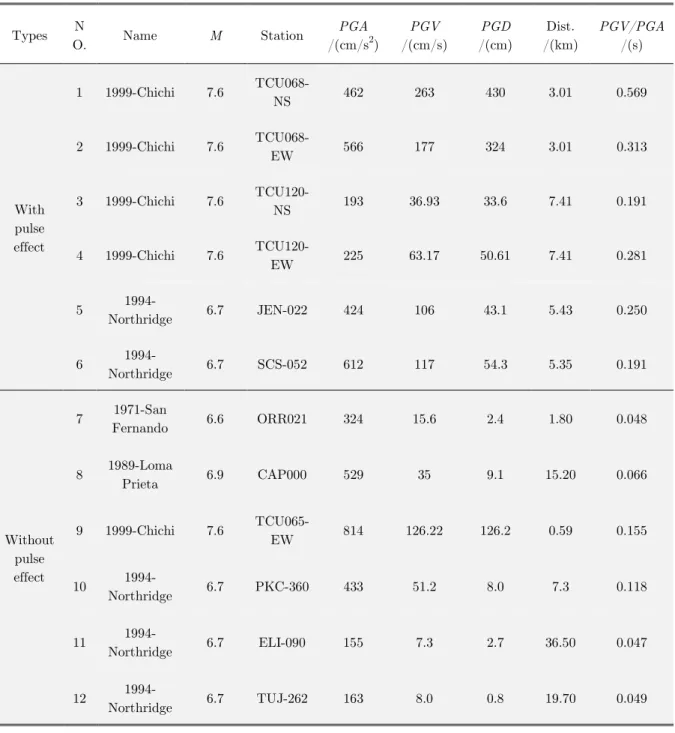
In general, near-fault pulse-type ground motions have a high acceleration、velocity、amplitude of displacement time history, rich low-frequency component, long cycle and short duration. According to Somerville and Yang, there is a judgment for velocity pulse ground motions, when the ratio of PGV/PGA to around or larger than 0.2 (Somerville et al, 1997 and Yang et al, 2005). The records of earthquake events in the past are as the seismic input in this paper and all ground motion rec-ords from the Pacific Earthquake Engineering Research center (PEER) database, as shown in Table 1. Among them, No.1-No.6 are the near field pulse ground motions and No.7-No.12 are non-pulse ground motions. For better analyze the effect in limiting relative displacement of cable-sliding mod-ular expansion joints (CMEJs), 12 waves' PGA is adjusted to 0.6g and 5% damping ratio. Figure 1 is the acceleration response spectra corresponding to the selected ground motions.
Latin A m erican Journal of Solids and Structures 12 (2015) 1397-1414 Types N
O. Name M Station
PGA
/(cm/s2)
PGV
/(cm/s)
PGD
/(cm)
Dist. /(km)
PGV/PGA
/(s)
With pulse effect
1 1999-Chichi 7.6
TCU068-NS 462 263 430 3.01 0.569
2 1999-Chichi 7.6
TCU068-EW 566 177 324 3.01 0.313
3 1999-Chichi 7.6
TCU120-NS 193 36.93 33.6 7.41 0.191
4 1999-Chichi 7.6
TCU120-EW 225 63.17 50.61 7.41 0.281
5
1994-Northridge 6.7 JEN-022 424 106 43.1 5.43 0.250
6
1994-Northridge 6.7 SCS-052 612 117 54.3 5.35 0.191
Without pulse effect
7 1971-San
Fernando 6.6 ORR021 324 15.6 2.4 1.80 0.048
8 1989-Loma
Prieta 6.9 CAP000 529 35 9.1 15.20 0.066
9 1999-Chichi 7.6
TCU065-EW 814 126.22 126.2 0.59 0.155
10
1994-Northridge 6.7 PKC-360 433 51.2 8.0 7.3 0.118
11
1994-Northridge 6.7 ELI-090 155 7.3 2.7 36.50 0.047
12
1994-Northridge 6.7 TUJ-262 163 8.0 0.8 19.70 0.049
Latin A m erican Journal of Solids and Structures 12 (2015) 1397-1414 Figure 1: Acceleration response spectra corresponding to the selected ground motions.
3 BASICS, STRUCTURE AND RESTORING FORCE MODEL OF CMEJS
3.1 Basics of CMEJs
With the improvement in the overall performance of the cable materials, the cable can effectively enlarge mechanical properties, and it has been widely used in such fields as prestressed concrete structure、cable-stayed bridge、bridges' displacement-limited and isolation, etc. In addition, cable has become the most active and potential material in modern structures.
Abdel-Ghaffar et al analyzed Aptos Creek Bridge which used cable restrictor under 1989 Amer-ica Loma Prieta earthquake, and drew the following conclusion: the device has little response to earthquake at the bridge site, but it can lessen the force and displacement of structure response under strong earthquake (Abdel-Ghaffar et al, 1997). To assess the force-displacement relationship of cable restrictor device, Reginald et al carried out a full-scale model test of multi-span simply supported girder bridge which used the device in Tennessee and found that the main failure modes were not cables damage, but the connecting components destructed firstly and cables’ capacity has not been fully exploited; Then he conducted the modified connecting components test, in order to ensure that it has higher strength and damages less than the cable restrictor (Reginald et al,2003).
Seismic specifications for highway bridges including Caltrans, AASHTO, specifications of Japan and China all mentioned that using cable-sliding devices to restrict relative displacement between girders, especially, the AASHTO also mentioned that the devices should be set more flexible and convenient to check and replacement (Caltrans,2006; AASHTO,2007;JRA,1996;CCP,2008).
Practice has proved that the application of cable in limiting displacement is very extensive in civil engineering and cable has a good effect. These experiences are worth emulating.
0.0 0.5 1.0 1.5 2.0 2.5 3.0 3.5 4.0
0.0 0.2 0.4 0.6 0.8 1.0 1.2 1.4 1.6 1.8 2.0 2.2 2.4 2.6
NO.1 NO.7
NO.2 NO.8
NO.3 NO.9
NO.4 NO.10
NO.5 NO.11
NO.6 NO.12
Mean spectrum of PE
Mean spectrum of without PE
A
c
c
e
leration
/g
Latin A m erican Journal of Solids and Structures 12 (2015) 1397-1414
3.2 Structure and restoring force model of CMEJs
Continuous beam bridge will cause oversized relative displacements between pier and girder under earthquake, which may lead to severe collision of superstructure, even girder falling. Aiming at this problem, this paper puts forward a device named cable-sliding modular expansion joints (CMEJs) that can control the relative displacement and avoid collision.
In a modular expansion joint, there is a support box every few meters along the transverse di-rection of the bridge, as shown in Figure 2
.
Based on the conventional design, CMEJs use the cable through the both ends of the support boxes and support bars and connect them. When earthquake occurs, the relative displacement between beams is limited through controlling movement of bars in the boxes by cables. Because both ends of the support boxes are fixed in the two ends of the beams, the cable can limit the relative displacement of beams. CMEJs does not exist right now and it is the latest design. For more details, we will introduce it in additional studies. Moreover, the premise is that connected units do not damage before cables. Figure 3 is the working mechanism of CMEJs.Center beams Seal Bridge girder
Yokes Sliding bearing
Support bar
Sliding spring Edge beam Bridge girder
Figure 2: Cross-section view of a CMEJs system.
Close
Far away
Figure 3: Working mechanism of CMEJs
(b) Normal state of a CMEJs system
Latin A m erican Journal of Solids and Structures 12 (2015) 1397-1414 When the adjacent girders get close and an impending collision,the cable can control the girders to prevent collision and play a role in limiting the relative displacement, as shown in Figure 3(d); And vice versa, as is shown in Figure 3(c). In addition, as the cable is running through support boxes and bars, CMEJs will not be easily damaged. According to the requirements of different bridge structural design, adjusting cable free movement can realize the limiting effect. When an earthquake occurs, if the relative displacement between the girders is within the free movement, the cables do not work; if larger than the free movement, they can work effectively.
This paper does not consider expansion joint itself constitutive model. According to Emily et al, the expansion joint has little function of limiting the relative displacement (Emily et al 2014), but it is limited and far less than the cables' stiffness. What's more, the cases of expansion joints damages before cables are not in the scope of our considering.
4 ANALYSIS MODEL
4.1 General information of model
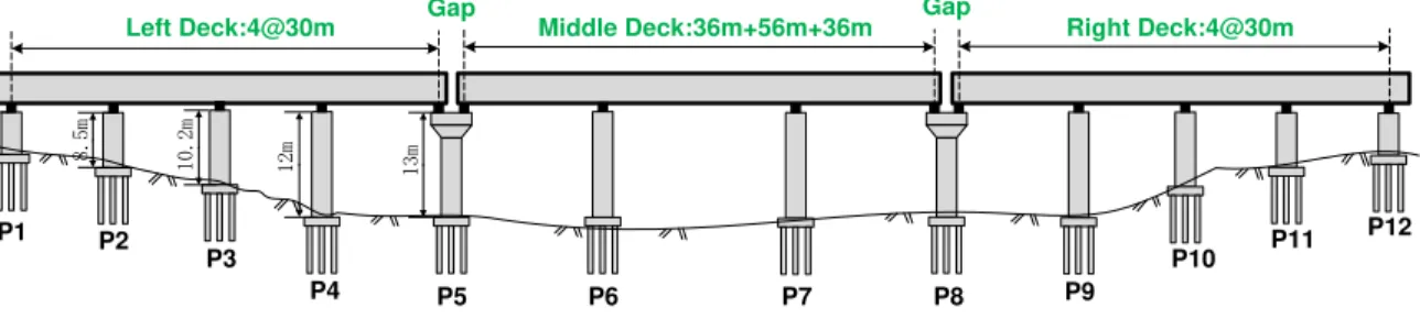
Figure 4 is a triple continuous beam bridge (4×30m+36+56+36+4×30m) and its superstructures adopt the prestressed concrete box girders with variable cross section constructed by simple sup-ported-continuous system, deck width 23.3m. Its substructures are double-column bridge piers and 9 piles under each pile cap, pile diameter 1.5m. In this paper, we do not consider the effect of abutment. Table 2 is the cross-sectional properties of piers. Figure 8 and Table 3 are the details of the bearings.
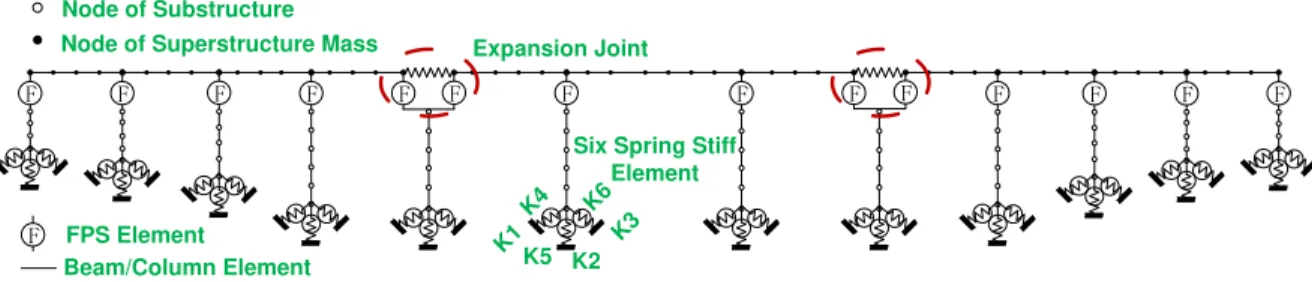
According to the design, a three-dimensional dynamic finite element model is established and girders、piers are simulated as space beam and column element. Pile cap simulate as a particle and secondary dead load is imposed on the beam in linearly distributed weight, as is shown in Figure 5. By summarizing the previous earthquake damage of bridges, we found that collision and beam fall-ing mostly occurred in longitudinal direction. So in this paper only longitudinal inputs are consid-ered. Nonlinear time-history method is used to analyze the seismic response and using the transient direct integration method.
6.5m 8.5m 10.2m
12m 13m
Left Deck:4@30m Middle Deck:36m+56m+36m Right Deck:4@30m
P1 P2
P7 P3
P4 P5 P6 P9
P10 P11 P12
P8
Gap Gap
Latin A m erican Journal of Solids and Structures 12 (2015) 1397-1414
F F F F F F F F F F F F F F
Expansion Joint Node of Substructure
Node of Superstructure Mass
F FPS Element
Beam/Column Element
Six Spring Stiff Element
K1
K2
K3 K4 K6
K5
Figure 5: Finite element model of isolated bridge with FPS bearings and CMEJs.
F
u
g
pk
eF
u
k
fFigure 6: Force vs. displacement relation of CMEJs Figure 7: Typical bilinear FPS hysteresis/
P1
30m
P2
30m
P3
30m
P4
30m
P5
36m
P6
56m
A
B
C
B
A
D
E
Longitudinal direction
Bidirectional movable bearings
Latin A m erican Journal of Solids and Structures 12 (2015) 1397-1414 Structure
component Area, A(m
2) Torsion Constant,
J(m4) I33(m4) I22(m4)
P1~P5 3.6 1.804035 0.972 1.2
P6~P7 4.8 3.175031 2.304 1.6
P8~P12 3.6 1.804035 0.972 1.2
Table 2: Cross sectional properties of piers.
FPS Types
Effective Stiffness (kN/m)
Yield Strength (kN)
Stiffness (kN/m)
Post Yield Stiffness Ratio
Yielding Exponent
A 1750 175 87500 0.02 9
B 1920 480 240000 0.01 9
C 1660 415 207500 0.01 9
D 1650 165 82500 0.02 9
E 3017 905 452500 0.008 9
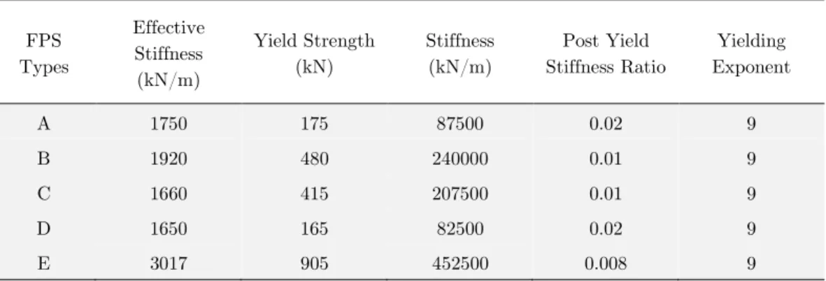
Table 3: FPS base isolation system parameters.
4.2 Expansion joint model
The seismic response of the target model was investigated by SAP2000 V15.1 in this paper. The damping ratio of the concrete structure is 5%. The damping mechanism is introduced in the analy-sis through the Rayleigh damping matrix. Figure 6 is the force vs. displacement relation of CMEJs. In addition, according to Karayannis and Favvata, Collisions are simulated using special purpose contact elements that become active when the corresponding nodes come into contact. The contact element responds as a spring with almost infinite stiffness (Karayannis, Favvata,2005 and Kara-yannis, Favvata , 2009).
The stiffness � and the restoring force � of the cables are expressed as:
� = {�̃ ∆0 ∆�> ∆�
�≤ ∆� (1)
� = {�(∆0 ∆�− ∆�) ∆�− ∆�> 0
�− ∆�≤ 0 (2)
where ∆� is the initial clearance between two decks, ∆� is the relative displacement between the
adjacent decks, and �̃ is the stiffness of the cables. The stiffness �̃ is determined from
�̃ =���� (3)
Latin A m erican Journal of Solids and Structures 12 (2015) 1397-1414
4.3 Simulation of the Pile Foundation
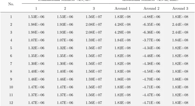
The commonly used processing method for pile foundation is adding a 6×6 stiffness matrix to simulate the pile-soil interaction under pile cap. Spring stiffness depends on soil conditions and the layout of piles, which can be calculated by the principle of equivalent static. This proposed method is simple but efficient, and widely used in low cap pile foundation (Tang et al.2008). Figure 9 is the six springs’ model of pile foundation. Table 4 is the spring stiffness value of each pile foundation. It
should be noted that 1 axis represents longitude direction,2 axis represents transverse direction,3
axis represents vertical direction.
Figure 9:Six springs’ model of pile foundation.
No.
Translational stiffness kN/m Rotational stiffness kN·m/Rad
1 2 3 Around 1 Around 2 Around 3
1 1.53E+06 1.53E+06 1.56E+07 1.83E+08 -4.88E+06 1.83E+08
2 1.98E+06 1.93E+06 2.08E+07 4.28E+08 -6.35E+06 2.44E+08
3 1.98E+06 1.93E+06 2.08E+07 4.29E+08 -6.36E+06 2.44E+08
4 1.07E+06 1.07E+06 1.59E+07 1.84E+08 -3.77E+06 1.84E+08
5 1.32E+06 1.32E+06 1.56E+07 1.82E+08 -4.34E+06 1.82E+08
6 1.35E+06 1.35E+06 1.56E+07 1.82E+08 -4.46E+06 1.82E+08
7 1.30E+06 1.30E+06 1.56E+07 1.82E+08 -4.38E+06 1.82E+08
8 1.40E+06 1.40E+06 1.56E+07 1.83E+08 -4.58E+06 1.83E+08
9 1.46E+06 1.46E+06 1.59E+07 1.86E+08 -4.70E+06 1.86E+08
10 1.47E+06 1.47E+06 1.56E+07 1.83E+08 -4.71E+06 1.83E+08
11 1.37E+06 1.37E+06 1.56E+07 1.82E+08 -4.47E+06 1.82E+08
12 1.47E+06 1.47E+06 1.56E+07 1.83E+08 -4.71E+06 1.83E+08
Table 4: Spring stiffness value of each pile foundation
(a) Elevation drawing (b) Planar drawing
Six springs at cap bottom:
Translation:Kx,Ky,Kz
Latin A m erican Journal of Solids and Structures 12 (2015) 1397-1414
4.4 Case analysis
In order to analyze the seismic response of isolated bridges with CMEJs under near-fault earth-quake, the following four cases are established, respectively:
Case I: The bridge model without CMEJs and pulse effect. Case II: The bridge model without CMEJs and with pulse effect Case III: The bridge model with CMEJs and without pulse effect Case IV: The bridge model with CMEJs and pulse effect
Isolated bridge adopts friction pendulum bearings, which are widely used in engineering practice. Figure 7 is typical bilinear FPS hysteresis. In general, the expansion joint's clearance is determined by static calculation. The number is 10cm in this paper which means when the compression defor-mation is greater than 10cm, it can be considered that adjacent girders has been collided. In order to satisfy the requirements of the bridge temperature change and normal operation, the gap was assumed 0.08m in this analysis. If the relative displacement between girders is larger than 8cm, cable can play its roles; if the displacement is larger than 10cm, the cables can be seen as failing to achieve the expected goals.
5 SEISMIC RESPONSE WITH OR WITHOUT CMEJS UNDER NEAR-FAULT GROUND MOTIONS
To study the effect of the CMEJs under near-fault ground motions, the above analytical model for CMEJs was implemented to the target bridge as shown in Figure 4. Because the structure is sym-metrical, we only consider the half bridge as discussed in this paper. To better reveal the effect of CMEJs in limiting the relative displacement of the adjacent girders under six pulse-type ground motions, we introduced the seismic response in detail under No.1 and No.5 as seen in Figure 10 and 11.
0 5 10 15 20 25 30
-0.8 -0.6 -0.4 -0.2 0 0.2 0.4
A
c
c
e
lera
tion
(
g
)
Time (sec)
No.1
Latin A m erican Journal of Solids and Structures 12 (2015) 1397-1414
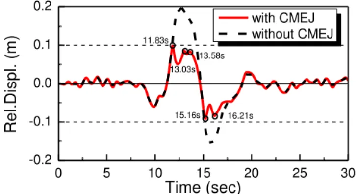
Figure 12 shows the relative displacement between left deck and middle deck under the No.1 ground motion. The responses of neglecting the effect of CMEJs in the analysis are also shown in Figure 12 for comparison. The relative displacement between left deck and middle deck by disre-garding the effect of CMEJs are about +0.2m and -0.18m in tensile and compressive directions, respectively, which is larger than gap and pounding occurred. On the other hand, this value be-comes +0.098m and 0.091m in the tensile and compressive directions, respectively, if the CMEJs is included in the analysis. Thus, the relative displacement decreased by 50% and 49% by including the CMEJs in the analysis in the tensile and compressive directions, respectively.
Figure 14 shows the pulling force of CMEJs under the No.1 ground motion. There are three times in the tensile direction and two times in the compressive direction, which is also clear in Fig-ure 12. Because the free movement of cables is 8cm, the cables can work when the gap is larger than 8cm. As is obvious from Figure 10, there is pulse acceleration with high magnitude spikes from 8s to 15s. So we can see from Figure 12 and 14, the cables' pulling force are 7.4MN,2.1MN and 1.21MN at 11.83s,13.025s and 13.58s in the tensile direction and 4.5MN,1.68MN at 15.165s and 16.205s in the compressive directions. Similarly, the effect of CMEJs is obvious as shown in Figure 11 and 13 under the No.5 ground motion. But the difference is that No.5 has two pulse accelera-tions, so the Figure 13 and 15 both have a symmetrical property.
In conclusion,in the bridge with CMEJs, the peak relative displacement between the adjacent girders is significantly decreased, thus avoiding collision. The relative displacement of adjacent gir-ders can be reduced within 0.1m by setting a reasonable length of free movement. The installation of a CMEJs can reduce the relative displacement and achieve a more economical design.
0 5 10 15 20 25
-0.4 -0.2 0 0.2 0.4 0.6
A
c
c
e
lera
tion
(
g
)
Time (sec)
No.5
Latin A m erican Journal of Solids and Structures 12 (2015) 1397-1414 Figure 12: Relative displacement between Left deck and Middle deck under the No.1 near-fault ground motion.
Figure 13: Relative displacement between Left deck and Middle deck under the No.5 near-fault ground motion.
Figure 14: Pulling force of the CMEJs under the No.1 near-fault ground motion.
Figure 15: Pulling force of the CMEJs under the No.5 near-fault ground motion.
0 5 10 15 20 25 30
-0.2 -0.1 0.0 0.1 0.2 16.21s 15.16s 13.03s 13.58s R e l. D is p l. ( m) Time (sec) with CMEJ without CMEJ 11.83s
0 5 10 15 20 25
-0.15 -0.10 -0.05 0 0.05 0.10 0.15 8.28s 6.74s Re l. Dis p l. ( m) Time (sec) with CMEJ without CMEJ 5.52s
5 10 15 20 25 30
-6 -3 0 3 6 9 Pu lling f o rc e ( MN ) Time (sec)
5 10 15 20 25
Latin A m erican Journal of Solids and Structures 12 (2015) 1397-1414 6 SEISMIC RESPONSE WITH PULSE EFFECT OR WITHOUT PULSE EFFECT IN CONSIDERING THE EFFECT OF CMEJS
Effect of near-fault earthquakes on bridges has high-energy pulse movement characteristics, which includes: long cycles, obvious peak velocity, acceleration and a duration waveform similar to pulse. Velocity pulse will increase the acceleration, velocity, displacement impact. For small damping, the effect of velocity pulse is larger and it allows bridges under high-energy impact, which may result in large displacements and deformations. To explain the seismic response with PE (pulse effect) or without PE (pulse effect) in considering CMEJs, the response of bridge under No.2 and No.8 ground motion were analyzed. As is obvious from Figure 16, the No.2 has significant pulse accelera-tion within 9-13s. Though they have the same PGA, but No.8 does not have such features.
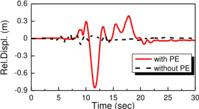
Figure 17 shows the relative displacement between decks and piles and used left deck and P5 as an example. It is important to note that the relative displacements are significantly amplified if the PE is considered in analysis. The maximum relative displacement is -0.85m at 11.6s and +0.38m at 17.38s by taking account of the PE. However, this value is -0.11m at 9.06s and +0.07m at 7.2s by disregarding the PE. That means when near-fault earthquakes occur, the relative dis-placement between decks and piles becomes 7.2 times or 5.4 times the disdis-placement without pulse effect for the seismic isolation bridges. From this figure,we can see that CMEJs cannot work very well in restraining the relative displacement between piers and girders. Once the relative displace-ment is larger than allowable displacedisplace-ment (overlap length), girder falling will occur. Whether the cables can hold the girders or not, further work is needed to validate this point. But in theory, the capacity of cables can satisfy the requirements.
Figure 16: The No.2 and No.8 ground motion records in the anslysis.
Figure 17: The relative displacement between left deck and P5.
0 5 10 15 20 25 30
-0.6 -0.4 -0.2 0.0 0.2 0.4 0.6
A
c
c
e
lera
tion
(
g
)
Time (sec)
No.2 No.8
0 5 10 15 20 25 30
-0.9 -0.6 -0.3 0 0.3 0.6
R
e
l.
D
is
p
l.
(
m)
Time (sec)
Latin A m erican Journal of Solids and Structures 12 (2015) 1397-1414 Figure 18: Relative displacement between left deck and middle deck.
Figure 19: Pulling force of the CMEJ with PE or without PE.
Figure 20: Displacement at the right end of the left deck.
Figure 21: Acceleration at the right end of the left deck.
0 5 10 15 20 25 30
-0.12 -0.08 -0.04 0 0.04 0.08 0.12 -0.1m Re l. Dis p l. ( m) Time (sec) with PE without PE +0.1m
0 5 10 15 20 25 30
-8 -6 -4 -2 0 2 P u lling f o rc e ( MN ) Time (sec) with PE without PE
0 5 10 15 20 25 30
-1.0 -0.8 -0.6 -0.4 -0.2 0 0.2 0.4 0.6 D is p l. ( m) Time (sec) with PE without PE
0 5 10 15 20 25 30
Latin A m erican Journal of Solids and Structures 12 (2015) 1397-1414
Figure 18 shows the relative displacement between adjacent girders with PE or without PE. Focus-ing on the responses durFocus-ing 10-20s, the displacements significantly amplified with PE. The relative displacements are 0.017m at 12.39s and 0.025m at 20.565s by disregarding the PE, while those val-ues are 0.095m at 11.765s and 0.083m at 17.925s by taking account of PE. It is found that when near-fault earthquakes occur, the relative displacements are 5.58 times or 3.32 times the displace-ment without PE. However, the displacedisplace-ments are restricted to 0.1m when the CMEJs are installed and collision will not occur. On the other hand, the decks without CMEJs will be destroyed by pounding and aggravated the destruction of piers and girders under near-fault earthquake. Figure 19 shows the corresponding pulling forces at the expansion joints between left deck and middle deck.
Figure 20 is the displacement at the right end of the left deck. The maximum displacement is -0.897m at 11.645s and +0.413m at 17.86s by taking account of the PE. However, this value is 0.12m at 9.04s and +0.07m at 10.975s by disregarding the PE. And Figure 21 is corresponding ac-celeration at the right end of the left end. It is interesting to note that the shape of Figure 16 is very similar to Figure 21. As is obvious from Figure 21, there is significant pulse wave with PE.
7 COMPARISON OF FOUR CASES
The effectiveness of the CMEJs was investigated with PE or without PE. To illustrate the effect of CMEJs with PE or without PE, Table 5 shows the average results of shear force of P5, bending moment of P5, and shear force of P6, bending moment of P6, bearing displacement at P5 under 12 ground motions (6 with PE and 6 without PE). As is obvious from Table 5, all the five indexes have significantly increased by 1.90-3.95 times. Therefore, in the situations of pulse effect, neglect-ing its possible effects leads to non-conservative designs. However, there is no substantial change of the five indexes with CMEJs in comparison with without CMEJs. So the installation of CMEJs can be a protection device for the bridge near the earthquake fault zone and limit the relative displace-ment of the adjacent girders.
Cases Without PE With PE With PE/without PE
Shear force of P5(MN)
with CMEJs 1.66 3.16 1.90
without CMEJs 1.66 3.16 1.90
with CMEJs/without CMEJs
1.00 1.00 -
Bending moment of P5(MN·m)
with CMEJs 10.66 23.38 2.19
without CMEJs 10.66 23.34 2.19
with CMEJs/without CMEJs
1.00 1.00 -
Shear force of P6(MN)
with CMEJs 1.65 4.20 2.55
without CMEJs 1.65 4.18 2.54
with CMEJs/without CMEJs
1.00 1.00 -
Bending moment of P6(MN·m)
with CMEJs 20.02 52.18 2.61
without CMEJs 20.00 51.98 2.60
with CMEJs/without CMEJs
1.00 1.00 -
Bearing displacement at P5(m)
with CMEJs 0.14 0.56 3.93
without CMEJs 0.14 0.57 3.95
with CMEJs/without 1.00 0.99 -
Latin A m erican Journal of Solids and Structures 12 (2015) 1397-1414 8 CONCLUSIONS
A new device named cable-sliding modular expansion joints (CMEJs) was developed to investigate the effect of controlling the relative displacement and avoid collision. The proposed model was im-plemented to an analysis of a triple continuous isolation bridge, which has different heights of piers with PE or without PE. Although experimental verification for the evaluation of properties of CMEJs is required, the following conclusions may be deduced from the analytical results presented herein.
1. For the bridge with CMEJs, the peak relative displacement between the adjacent girders is signif-icantly decreased, thus avoiding collision. The relative displacement of adjacent girders canbe re-duced within safety range by setting a reasonable length of free movement. The installation of CMEJs can reduce the relative displacement achieving a more economical design.
2. CMEJs cannot work very well in restraining the relative displacement between piers and girders. Once the relative displacement is larger than allowable displacement (overlap length), girder falling will occur. Whether the cables can hold the girders or not, further work is needed to validate this point. But in theory, the capacity of cables can satisfy the requirements.
3. Pulse effect can significantly increased the seismic responses of bridges located near fault zone, especially for seismic isolation bridges. The disregarding of PE is dangerous for them and leads to non-conservative design.
4. The installation of CMEJs has no substantial change to the responses of the bridges with PE or without PE for seismic isolation bridges. But it can be a protection device for the bridge and limit the relative displacement of the adjacent girders.
Acknowledgments
This research is supported by the Ministry of Science and Technology of China under Grant No.SLDRCE14-B-14, and by the National Natural Science Foundation of China under Grants No.51278376 and No.90915011. Their supports are gratefully acknowledged.
References
Emily M,Timothy W,Jamie E.P,Reginald DesRoches,and Paul B(2014).Development of an Experimentally Validated Analytical Model for Modular Bridge Expansion Joint Behavior,Journal of Bridge Engineering19(235), 235–244. Saiidi M, Maragakis E, Feng S(1996). Parameters in bridge restrainer design for seismic retrofit.ASCE Journal of Structural Engineering122(1):61–8.
Kawashima K, Shoji G(2000). Effect of restrainers to mitigate pounding between adjacent decks subjected to a strong ground motion. In: Proceedings of the 12th World Conference on Earthquake Engineering.paper no. 1435. Ruangrassamee A, Kawashima K(2001). Relative displacement response spectra with pounding effect. Earthquake Engineering and Structural Dynamics 30:1511–38.
Latin A m erican Journal of Solids and Structures 12 (2015) 1397-1414
DesRoches R, Muthukumar S (2002). Effect of pounding and restrainers on the seismic response of multi-frame bridges. ASCE Journal of Structural Engineering128(7):1–10.
Ancich,E. J.,Chirgwin, G.J., and Brown, S. C.(2006). Dynamic anomalies in a modular bridge expansion joint. Jour-nal of Bridge Engineering 11(5), 541–554.
Crocetti, R., and Edlund, B. (2003). Fatigue performance of modular bridge expansion joints. Journal of performance of constructed facilities17(4), 167–176.
Dexter,R.J.,Connor,R.J.,and Kaczinski, M.R.(1997).Fatigue design of modular bridge expansion joints. Transporta-tion Research Board(TRB), NaTransporta-tional Cooperative Highway Research Program (NCHRP)Rep.402, NaTransporta-tional Academy Press, Washington, DC.
Dexter,R.J.,Mutziger, M., and Osberg,C.(2002).Performance testing for modular bridge joint systems. Transportation Research Board (TRB),National Cooperative Highway Research Program (NCHRP) Rep. 467,National Academy Press, Washington, DC.
Dexter, R. J.,Osberg, C., and Mutziger,M. (2001). Design, specification, installation, and maintenance of modular bridge expansion joint systems. Journal of Bridge Engineering 6(6), 529–538.
Roeder, C. W. (1993). Fatigue cracking in modular expansion joints, Washington State DOT, Olympia, WA. Quan, G.,and Kawashima, K(2010). Effect of finger expansion joints on seismic response of bridges,Structural Engi-neering and Earthquake EngiEngi-neering,27(1),1–13.
McCarthy, E; Wright, T.; Padgett, J.E.; DesRoches, R.; Bradford, P(2012). Proceedings of the 2012 Structures Con-gress. Structures Congress , p 708-17.
Ramanathan, K. (2012). Next generation seismic fragility curves for California bridges incorporating the evolution in seismic design philosophy. Ph.D thesis, Georgia Institute of Technology, Atlanta.
Loh, CH, Wan, SU,Liao, W I(2002).Effects of hysteretic model on seismic demands: Consideration of near-fault ground motions.The Structural Design of Tall Building,11:155-169.
Yang D X, Li G, Cheng G D(2005). Seismic response of base-isolated structure subjected to near-fault pulse-like ground motions.Earthquake Engineering and Engineering Vibration25(2):119-124.
Abdel-Ghaffar S. M., Maragakis E. M., & Saiidi M. S(1997).Effects of the hinge restrainers on the response of the Aptos Creek Bridge during the 1989 Loma Prieta Earthquake. Earthquake spectra13(2): 167-189.
DesRoches R., Pfeifer T., & Leon R. T., et al(2003). Full-scale tests of seismic cable restrainer retrofits for simply supported bridges. Journal of Bridge Engineering 8(4): 191-198.
Caltrans Seismic Design Criteria(2006). Design manual-version 1.4, California Department of Transportation, Sac-ramento(California).
Japan Road Association(JRA)(1996). Seismic Design-Design Specifications for Highway Bridges,Part V.Tokyo, Ja-pan. (in Japanese).
AASHTO.LRFD Bridge Design Specifications, 4th Ed(2007).American Association of State Highway and Transpor-tation Officials, Washington, DC.
Tang, G. W., Li, J. Z., Tao, X. X., et al. (2008). Guidelines for Seismic Design of Highway Bridges. Beijing: China Communications Press. (in Chinese).
Karayannis, Favvata(2005), Earthquake induced interaction between adjacent reinforced concrete structures with non-equal heights, J Earthquake Engineering and Structural Dynamics, Vol. 34, No. 1.
Favvata, Karayannis et al(2009), Influence of exterior joint effect on the inter-story pounding interaction of struc-tures, J. Structural Engineering and Mechanics, Vol.33, No.2.