ABSTRACT
and cast implant single abutment
Rudys Rodolfo DE JESUS TAVAREZ1, Wellington Cardoso BONACHELA2, Anuar Antônio XIBLE3
1- DDS, MSc, PhD, Professor, Maranhão University Center (UNICEUMA), São Luis, MA, Brazil.
2- DDS, MSc, PhD, Professor, Department of Prosthodontics, Bauru School of Dentistry, University of São Paulo, Bauru, Brazil. 3- DDS, MSc, PhD, Adjunct Professor, Department of Prosthodontics, Federal University of Espírito Santo, Vitória, ES, Brazil.
Corresponding address: Prof. Dr. Rudys Rodolfo De Jesus Tavarez - Rua Projetada II Q-i C-03 JD Libanês Olho D’Agua, São Luis-MA - 65067-560 - Phone: 98-3226-3217 / 98-3227-2360 - e-mail: [email protected] ; [email protected]
!
O
bjectives: The purpose of this in vitroimplant/abutment interface of external and internal connection implant systems when subjected to cyclic loading. Material and Methods: Standard metal crowns were fabricated for 5 groups (n=10) of implant/abutment assemblies: Group 1, external hexagon implant and UCLA cast-on premachined abutment; Group 2, internal hexagon implant and premachined abutment; Group 3, internal octagon implant and prefabricated abutment; Group 4, external hexagon implant and UCLA cast-on premachined abutment; and Group 5, external hexagon implant and Ceraone abutment. For groups 1, 2, 3 and 5, the crowns were cemented on the abutments and in group 4 crowns were screwed directly on the implant. The specimens were subjected to 500,000 cycles at 19.1 Hz of frequency and non-axial load of 133 N !"#$ evaluated before (B) and after (A) application of the cyclic loading. Data were analyzed statistically by using two-away ANOVA and Tukey’s post-hoc test (p<0.05). Results: Before loading values showed no difference among groups 2 (4.33±3.13), 3 (4.79±3.43) and 5 (3.86±4.60); between groups 1 (12.88±6.43) and 4 (9.67±3.08), and among groups %&'*+&>*> >%&'? @>>!E%IEE#*!EEIJJ#> different from those of groups 2 (4.83±4.50), 3 (8.07±4.31) and 5 (3.81±4.84). There was >>&'* >& groups 2 and 5. Conclusions: The cyclic loading and type of implant/abutment connection $
Key words:KP
INTRODUCTION
The treatment option of single-implant supported restorations has been largely accepted by the outcomes of longitudinal studies reported in the literature12-28. In spite of high prosthetic success
rates, mechanical complications are commonly found on such restorations, and the most frequent is the loosening of the screw that connects prosthesis to the implant. Simon29 (2003) reported 7% of
screw loosening for single-implant supported molar and premolar crowns after a ten-year follow-up29.
A more recent extensive critical review reported a cumulative incidence of screw loosening of 12.7%
after 5 years18. The problems related to this type
of complication yield overload and injury to the implant/bone interface, besides the long time and high costs required for prosthetic reconstruction4.
Interactions between clinical and laboratorial aspects such as implant components impairment, are reported as possible causes for screw loosening leading to loss of preload, which is the tension delivered on the screw when torque is applied upon tightening14,27.
large groups of implant connection, namely external and internal, a greater stability of the implant/ abutment interface has been correlated to internal connections in which the abutment walls are in close contact with the internal surface of the implant, reducing the possibility of micro-movements during loading2. In experimental studies where static and
dynamic loads are delivered to implant systems X&> improvement in the behavior was found for the internal connection1,9,10.
The passive fit at implant/abutment or of prosthetic cylinder abutment interface may also Y Z be passively fit and the screw is tightened in an attempt to enhance seating, damages to the internal connection threads may occur, leading to screw loosening and likelihood of fracture and implant loss4,7-22
can be assessed by measurement of the vertical misfit at the implant/prosthetic components interface3,20>20.
However, Tsuge, et al.30(2004) observed very low
microgap values for premachined internal and external connection implants, ranging from 2.3 μm to 5.6 μm, corroborating that even premachined abutments can present microgap at the implant/ abutment interface.
On the other hand, casting and polishing procedures on premachined cast-on components [Y8. Kano, et al.20
(2007)and Lewis, et al.23 (1988) demonstrated
that the use of cast burnout abutments can result >> ]& Y screw joint stability. Using a different methodology, Byrne, et al.7 !JJ#
premachined and premachined cast-on abutments to implants and concluded that casting-on with >^ > vertical adaptation of the premachined cast-on gold
UCLA abutments.
In regular prosthetic protocols premachined components are used to reduce the risk of mechanical complications22. In order to provide
more versatility in overcoming angulated and esthetic problems, plastic burn-out patterns UCLA abutments were introduced17. UCLA abutments
allow esthetic restoration to be finished very close to the implant head, solving many esthetic dilemmas. The use of this prosthetic option has > provided by premachined abutments7. Due to this
increased search for components many alternatives & premachined UCLA abutments.
Cyclic loading of the implant-prosthesis assembly induces micromotion of the joint components, which could wear down the microscopically rough areas of the contacted surfaces, contributing to screw loosening by decreasing the preload25. Among the
of the prosthesis21&>>13,14,26,
screw settling25 biomechanical overload26, and
differences in screw material or design19.
A cyclic loading test is intended to simulate components in function what permits analyze of a > > at the implant/abutment interface of premachined cast-on and premachined abutments of external and internal connections before and after cyclic loading.
MATERIAL AND METHODS
Distribution of groups
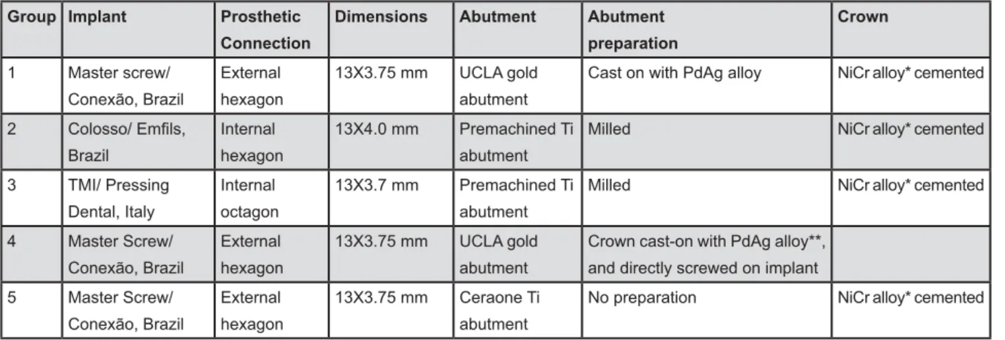
Five groups (n=10) of different implant systems selected for this study are shown in the Figure 1. The types of implant systems are illustrated in Figures 2 and 3. Implants were vertically embedded in hexagonal acrylic resin blocks and connected to
Group Implant Prosthetic
Connection
Dimensions Abutment Abutment
preparation
Crown
1 Master screw/
Conexão, Brazil
External
hexagon
13X3.75 mm UCLA gold
abutment
Cast on with PdAg alloy NiCr alloy* cemented
2
Brazil
Internal
hexagon
13X4.0 mm Premachined Ti
abutment
Milled NiCr alloy* cemented
3 TMI/ Pressing
Dental, Italy
Internal
octagon
13X3.7 mm Premachined Ti
abutment
Milled NiCr alloy* cemented
4 Master Screw/
Conexão, Brazil
External
hexagon
13X3.75 mm UCLA gold
abutment
Crown cast-on with PdAg alloy**,
and directly screwed on implant
5 Master Screw/
Conexão, Brazil
External
hexagon
13X3.75 mm Ceraone Ti
abutment
No preparation NiCr alloy* cemented
*Lite cast B, Will-Ceram, USA / **Porson 4 - Degussa Division, Dentsply, Germany.
the respective abutment. Abutments from groups 1, 2 and 3 were prepared to receive a cemented conventional crown. For group 1, UCLA premachined cast-on abutments were waxed with 6-mm height, 4 walls inclination and 1 mm cervical metal collar, and cast on with PdAg alloy (Porson 4 - Degussa Division, Dentsply, Germany). Premachined titanium abutments from group 2 and 3 were milled to same dimensions as group 1. Abutments from group 4 were waxed with a total height of 8 mm and an occlusal surface diameter of 8 mm, with screw access in the occlusal surface, and cast on with PdAg alloy. Abutments from group 5 were used as received.
For groups 1, 2, 3 and 5, cuspless premolar crowns were waxed with the same dimension as group 4 abutments (total height of 8 mm and an occlusal surface diameter of 8 mm with screw access in the occlusal surface) and cast with NiCr alloy (Lite Cast B, Will-Ceram, USA). For casting, abutments from each group were cast together by the same operator, following manufacturer’s alloy instructions. After investment, castings were sandblasted with glass beads at 2.8 Bar until complete cleaning. A 4x-magnifying lens was used to check the integrity abutments contact interface. Samples with internal cast imprecision X > ] [!@{|&P[&}@#@> and polishing procedures crowns were cemented to the abutments with zinc phosphate cement (Hy-Bond Zinc Phosphate Cement, Shofu, Japan) following the manufacturer´s instructions. For all groups titanium screws were used to screw the abutment to the implants with 30 Ncm torque, as recommended by manufacturer, using an analog
Figure 2- Implant systems used in the study: Intern Octagon (1); External Hexagon (2) and Intern Hexagon (3)
Figure 3- Prosthetic abutments used in the study. (1) UCLA Gold Abutment – groups 1 and 4; (2) Internal Hexagon Premachined Ti – group 2; (3) Internal Octagonal Premachined abutment – group 3; (4) Ceraone Ti – group 5
Figure 4- Reference points for measurement of the
24 (2007)
torquemeter (Tohnichi BTG60CN, Tokyo, Japan) with a precision of ±2%.
0HDVXUHPHQWRIYHUWLFDOPLV¿WDWLPSODQW abutment interface
Analyses were performed before (B) and after (A) cyclic loading by one examiner, using a microscope (Mitutoyo TM, model 5050, Mitutoyo Corporation, Tokyo, Japan), code 176-811A, under 150x > !?X X # micro-metric heads (code 164-162), with precision " X> allowed the samples to be evaluated in six sides. The occurrence of a vertical gap at the implant/ abutment interface, visible on the microscope through passage of light, was deemed as vertical }> ^ reference, the sample was positioned so that the X line passed through the horizontal platform of the implant and the vertical Y line crossed the X line at the most external point of the horizontal platform of the implant. The intersection between X and Y lines !# was measured for all specimens20 (Figure 4). For each
side, three measurements were recorded and a mean 6 sides, and it was recorded in micrometers.
Application of cyclic loading
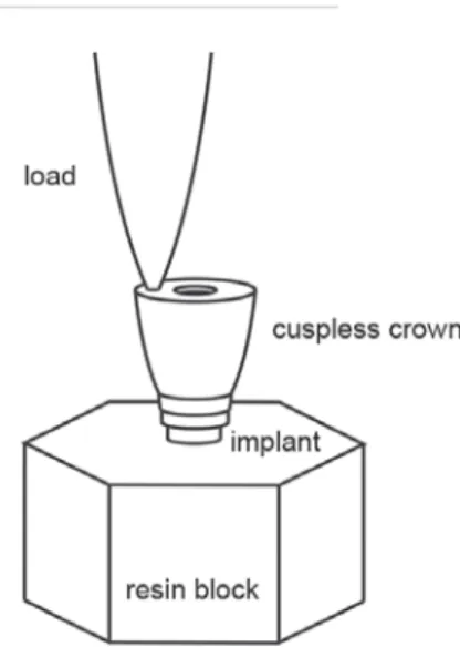
The cyclic loading test was performed on a Material Testing System, MTS-810 (MTS Corporation, USA) cyclic loading machine, with an axial load of 133 N, at a 3 mm laterally distant from the center of the implant, at a frequency of 19.1 Hz for 500,000 cycles (Figure 5). One sample of each group was loaded at the same time in the loading machine.
| treated using SPSS version 11.0 for Windows (SPSS Inc., Chicago, IL, USA) with ANOVA and Tukey post hoc tests (p<0.05)
RESULTS
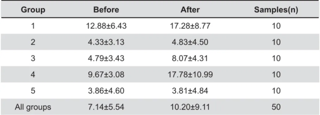
| loading for each group were displayed in Table 1. >>> (p<0.05).
Before cyclic loading, groups 1 (12.88±6.43 "#*!JEI'"#> > > ? !'I*"#!?#!%# > > internal (groups 2 and 3) and external connections (group 5) for premachined abutments before and after loading (p=0.38) (Table 3)
After cyclic loading, the highest values were > !E%IEE "# *
Group Before After Samples(n)
1 12.88±6.43 17.28±8.77 10
2 4.33±3.13 4.83±4.50 10
3 4.79±3.43 8.07±4.31 10
4 9.67±3.08 17.78±10.99 10
5 3.86±4.60 3.81±4.84 10
All groups 7.14±5.54 10.20±9.11 50
Table 1-!"## $
%& '
Group Mean (µm)
5 3.86
2 4.33
3 4.79
4 9.67
1 12.88
Table 2- Tukey test for comparisons of groups before fatigue test
Groups joined by a vertical bar did not present any $%+<<='
Group Mean (µm)
5 3.81
2 4.83
3 8.07
1 17.28
4 17.78
Table 3- Comparisons of groups after the fatigue test
!EEIJJ "#& >?!'I**"#&% !*'I*?"#'!EI*'"#!'#
Comparing each group before and after loading > in groups 1, 3 and 4 (Table 4).
DISCUSSION
This study compared the effect of cyclic loading in the vertical misfit at the implant/abutment interface of external and internal implant systems. { & Y > premachined and premachined cast-on abutments.
>20. However,
even the premachined abutments (groups 2, 3 and 5) showed discrepancy, but no difference was >> compared to each other despite the fact that they were different to each other in relation to the type of implant connection, i.e. external hex, internal hex and octagonal internal connection. Explanation ^ in the premachined groups may yield imprecise machining of implant parts4,22. The mean vertical
> from 3.81 μm to 8.07 μm are very similar to those found by Tsuge, et al.30 (2004) both for internal and
external hexagon connections, that ranged from 2.3 μm to 5.6 μm. This result corroborates that premachined abutments used in the present study have similar precision machining of components of other companies.
When comparing external hex connections systems, premachined cast-on abutments (group
*#> premachined abutments (group 5) for both before and after loading analysis. This may be due to the fact the premachined cast-on UCLA abutment used in groups 1 and 4 underwent to a laboratory process of casting, despite their premachined condition. On the other hand, premachined abutments used in groups 5, did not undergo any additional laboratory >* before and after loading results were compared. Y> 1 and 4, it seems reasonable to suggest that assemblies balance in these groups was unstable. This instability might have increased the movement between the abutment and the implant, screw loosening or implant deformation and consequently > when compared to before loading values.
The internal octagonal connection of group 3 also loading (Table 4). It was expected that this group where premachined abutments were used would not Y >@X this result can be attributed to the usual thin walls demanded for internal connections, which could be the weakest point allowing enlargement of implant upper border during the loading test and an increase } &[ of information for internal octagon implant system connections.
Kano, Binon and Curtis20 (2007) reported the
X>& premachined cast-on and plastic burnout abutments cast with NiCr or CoCr alloys to implants. They found values of 5.6±6.4; 11.1±8.2; 8.0±9.3 and 7.0±3.8 respectively. In a similar previous work, Kano, et al.21 !%*#
interface of premachined standard abutments and plastic burnout abutments cast with NiCr or CoCr alloys and found values ranging from 4.13±4.29 for the former group to 23,18±6.96 to CoCr group and 25,06±7.75 for NiCr group. Their results are in accordance with this work, when suggest that Y $ abutment interface.
Using a different methodology, Byrne, et al.7
!JJ# premachined cast-on external hex abutments at 2 sites: the abutment/implant interface and screw-to-screw seat. The authors concluded that casting-on >^ > }@ abutments joined to implants. However, even the premachined UCLA abutments of their study had few internal areas of contact with screw heads, what may suggest that even with well-adapted external
Group Loading '% *+<
1 Before 12.88±6.43a
After 17.28±8.77b
2 Before 4.33±3.13a
After 4.83±4.50a
3 Before 4.79±3.43a
After 8.07±4.31b
4 Before 9.67±3.08a
After 17.78±10.99b
5 Before 3.86±4.60a
After 3.81±4.84a
Table 4->? #
and after loading test (p<0.05)
areas, the internal cast-on abutment surface may >
The above studies did not used any aging & between different components. In the present study, cyclic loading test simulated components in { increased after loading for groups that presented >> >> that the use of premachined cast-on abutments & can get even worst when samples are subjected to loading.
CONCLUSION
From the obtained results, the following could be concluded:
1 - Premachined abutments presented better ^ for external hex implant connection, for both before and after loading analysis.
%^ >Y misfit values of premachined abutments with internal and external hex connections.
' ^ > premachined cast-on external hex abutments and premachined octagonal internal connection abutments.
REFERENCES
1- Aboyoussef H, Weiner S, Ehrenberg D. Effect of an antirotation resistance form on screw loosening for single implant-supported crowns. J Prosthet Dent. 2000;83(4):450-5.
2- Al-Turki LE, Chai J, Lautenschlager EP, Hutten MC. Changes in ^ prostheses. Int J Prosthodont. 2002;15(1):38-42.
'^PP$X> screw joint stability. Int J Prosthodont. 1996;9(2):149-60. 4- Binon PP. Implants and components: entering the new millennium. Int J Oral Maxillofac Implants. 2000;15(1):76-94. 5- Binon PP, McHugh MJ. The effect of eliminating implant/ {P 1996;9(6):511-9.
^>>&>&& Z{YX geometry and prosthetic table width on static and fatigue strength of dental implants. J Prosthet Dent. 1999;82(4):436-40. E^ K& + & & and premachined implant abutments. J Prosthet Dent. 1998;80(2):184-92.
^@&[&+ &>& and polishing procedures on preload in prostheses using conventional "gold" and plastic cylinders. Int J Oral Maxillofac Implants. 1996;11(5):589-98.
9- Cibirka RM, Nelson SK, Lang BR, Rueggeberg FA. Examination of the implant-abutment interface after fatigue testing. J Prosthet Dent. 2001;85(3):268-75.
10- Dellow AG, Driessen CH, Nel HJ. Scanning electron microscopy > dental implant systems. Int J Prosthodont. 1997;10(3):216-21.
11- Dixon DL, Breeding LC, Sadler JP, McKay ML. Comparison of >& & Y > designs. J Prosthet Dent. 1995;74(3):270-8.
12- Ekfeldt A, Carlsson GE, Börjesson G. Clinical evaluation of single-tooth restorations supported by osseointegrated implants: a retrospective study. Int J Oral Maxillofac Implants. 1994;9(2):179-83.
13- Gross MD, Kozak D, Laufer BZ, Weiss EI. Manual closing torque
in vitro comparative study.
J Prosthet Dent. 1999;81(5):574-8.
14- Haack JE, Sakagushi RL, Sun T, Coffey JP. Elongation and preload stress in dental implant abutment screws. Int J Oral Maxillofac Implants. 1995;10(5):529-36.
15- Jemt T. Cemented CeraOne and porcelain fused to TiAdapt abutment single-implant crown restorations: a 10-year comparative follow-up study. Clin Implant Dent Relat Res. 2009;11(4):303-10.
16- Jemt T, Lekholm U, Gröndahl K. A 3-year follow-up study of early single implant restorations ad modum Brånemark. Int J Periodontics Restorative Dent. 1990;10(5):340-9.
17- Jörnéus L, Jemt T, Carlsson L. Loads and designs of screw joints for single crowns supported by osseointegrated implants. Int J Oral Maxillofac Implants. 1992;7(3):353-9.
18- Jung RE, Pjetursson BE, Glauser R, Zembic A, Zwahlen M, Lang NP. A systematic review of the 5-year survival and complication rates of implant-supported single crowns. Clin Oral Implants Res. 2008;19(2):119-30.
19- Kallus T, Bessing C. Loose gold screws frequently occur in ^X > after 5 years. Int J Oral Maxillofac Implants. 1994;9(2):169-78. %^&PP&K@ the implant-abutment microgap. Int J Oral Maxillofac Implants. 2007;22(6):879-85.
21- Kano SC, Siqueira AF, Hussne R, Bonfante G. Use of base metal casting alloys for implant framework: marginal accuracy analysis. J Appl Oral Sci. 2004;12(4):337-43.
22- Khraisat A, Abu-Hammad O, Al-Kayed AM, Dar-Odeh N. Stability of the implant/abutment joint in a single tooth external-hexagon implant-system: clinical and mechanical review. Clin Implant Dent Relat Res. 2004;6(4):222-9.
23- Lewis S, Beumer J 3rd, Hornburg W, Woy P. The "UCLA"
abutment. Int J Oral Maxillofac Implants. 1988;3(3):183-9. 24- Lewis SG, Llamas D, Avera S. The UCLA abutment: a four-year review. J Prosthet Dent. 1992;67(4):509-15.
25- McAlarney ME, Stravropoulos DN. Determination of cantilever length-anterior-posterior spread ratio assuming failure criteria to be the compromise of the prosthesis retaining screw-prosthesis joint. Int J Oral Maxillofac Implants. 1996;11(3):331-9. 26- McGlumphy EA. Keeping implant screws tight: the solution. J Dent Symp. 1993;1:20-3.
27- McGlumphy EA, Mendel DA, Holloway JA. Implant screw mechanics. Dent Clin North Am. 1998;42(1):71-89.
28- Norton MR. Biologic and mechanical stability of single-tooth implants: 4- to 7-year follow-up. Clin Implant Dent Relat Res. 2001;3(4):214-20.
29- Simon RL. Single implant-supported molar and premolar crowns: a ten-year retrospective clinical report. J Prosthet Dent. 2003;90(6):517-21.