*e-mail: [email protected]
Some Aspects on Geometric and Matrix Work-hardening Characteristics of
Sintered Cold Forged Copper Alloy Preforms
Rajeshkannan Aa*,Devi S Rengamanib, Alok Sharmac,d
aDepartment of Mechanical Engineering, School of Engineering & Physics, Faculty of Science,
Technology & Environment, The University of the South Pacific – USP, Laucala Campus, Suva, Fiji bAyya Nadar Janaki Ammal College, Sivakasi, Tamil Nadu, India
cDepartment of Electrical & Electronics Engineering, School of Engineering & Physics,
Faculty of Science, Technology & Environment – USP, Laucala Campus, PMB, Suva, Fiji dInstitute for Integrated and Intelligent Systems, Griffith University, Australia
Received: February 18, 2013; Revised: September 9, 2013
Powder metallurgy (P/M) material subjected to plastic deformation results into densiication, however the extended deformation would not only enhance the densiication also supplements the strain hardening. Unlike fully dense material that would only undergo strain hardening while plastic deformation, the P/M material leads to pore closure as well; this phenomenon complicates the work hardening mechanism. The present study revealed that both strain and density conigures strengthening of P/M preform, which respectively termed as matrix and geometric work hardening. An attempt has been made to delineate some aspects of work hardening behaviour with the inluence of different aspect ratios of sintered and cold deformed copper alloy preforms. The preforms were initially prepared through conventional P/M route and inally subjected to cold upsetting under dry friction condition. A statistical analysis has also been introduced to study the quantitative impact of strain and density in the presence of aspect ratio on work hardening rate characteristics.
Keywords: work hardening, relative density, axial strain, aspect ratios
1. Introduction
Cold forging on sintered powder preforms would undergo both ductile fracture and strain hardening mechanisms, which in particular demonstrate the feasibility of forming processes. These mechanisms subsequently results in promoting densiication and mechanical properties in the inal products1,2. In general, ductile fracture is the
common mode of failure when material is subjected to plastic deformation3; this however is an obscured
phenomenon as it depends on many other parameters. For P/M materials, the factors can be broadly categorized into initial powder characteristics, process parameters, operating parameters and material parameters. A comprehensive review on ductile fracture in metal forming has been given by Alexandrov and Lyamina4. Ductile fracture of materials is
a consequence of void nucleation, growth and coalescence5,
in case of porous materials it is readily available so the extensive deformation results into void closure or fracture at free surfaces6. A ductile fracture model has been established
using the modiied Rice and Tracey approach by Straffelini and Fontanari for a plain carbon and an alloy or high strength steel. It was observed that the model was predicting the fracture criteria better for plain carbon steel as compared to the alloy steel. It is due to the microstructural heterogeneity of the alloy that overestimates the experimental equivalent fracture strains7. The shape of porosities that present in the
P/M preform governs and complicates the fracture criteria as it may not possess a regular geometry at every instant.
Using the self-consistent method, a ductile fracture criterion has been established by assuming the porosities shapes as a combination of spherical, cylindrical or disk. In which, voids are considered explicitly to propose a void coalescence criterion and is further considered as a homogenized continuum for porous plasticity models. The calibrated computational model is reported to successfully predict crack extension in various fracture specimens8.
Satsangi et al. proposed an elastic – plastic inite element method to analyze strain hardening phenomenon of porous material, when it is subjected to cold deformation in an incremental step. The variation of material parameters with relative density is also accounted to establish this model9.
Strain hardening is the consequence of plastic deformation of the material that can be expressed in mathematical form using Ludwik equation10. The constants in this
equation termed as K and n refer to strength coeficient
and hardening exponent due to strain respectively. The aforementioned phenomenon supplements complexity in P/M material due to explicit porosities associated with it. The closure of pores under extended deformation could be in the form of ductile fracture and subsequently enhance densiication along with promoting strain hardening. It was found that strain hardening could happen in the P/M material by means of matrix as well as geometric11; various attempts
had been made to explain this behavior with different compositions, preform geometries and friction conditions as major inluencing parameter12-16. However there were
incremental loading step of 0.02MN. After each step of loading, measurements of height, diameters (contact and bulged) using digital vernier caliper and density by invoking Archmedian principle and examination of the barreled surface of cracks were made. The preforms were deformed under dry friction condition. The schematic view of before and after deformation of the preform is shown in Figure 1.
3. Results and Discussion
3.1.
Work hardening characteristics
Figure 2 is drawn between low stress and true axial strain to exhibit copper preforms deformation characteristic under the influence of three different aspect ratios. Apparently, the nature of characteristic is found to be similar as such increasing strain increases low stress, however the proportion at which stress increases or behaves is different. Thus, a best curve itting technique is applied, as a consequence a third order polynomial curve with regression co-eficient of almost unity is observed. This reveals that stress behaves against strain in three different mechanisms; at initial stage, this falls between nil strain to 0.06 strain, its stress respectively zero to 262 MPa, relatively peak rise in stress. This may due to an initial applied incremental geometric and/or matrix strain hardening is happening,
as well as the level of contribution by each factor in the deforming preforms. In the present investigation an attempt has been made to rationalize this behaviour by considering copper alloy preform subjected to secondary deformation such as cold upsetting under dry friction condition. An empirical model has been suggested for work-hardening due to strain and densiication. Using this model, the work hardening rate characteristics has also been explained. Finally, using statistical analysis the contribution of material parameters such as relative density and axial strain with the inluence of various aspect ratios on work hardening rate has been quantiied.
2. Experimental Details
2.1.
Materials and characteristics
Electrolytic copper powder of less than 150 µm was procured and analysed for its purity, which was found to be 99.7% and the rest were insoluble impurities. The atomized aluminium powder and silicon powder of less than 37 µm size were also analyzed for its purity, which were found to be 99.93% and 99.90% respectively. All the aforementioned powders were obtained from M/S. Metal Powder Company, Thirumangalam, Madurai, Tamil Nadu, India.
2.2.
Powder blending and compaction
The required amount of powders corresponding to C64200 that is Cu-7%Al-1.8%Si were measured and blended in a pot mill along with porcelain balls of ratio 1:1 by weight for a period of 18 hours in order to obtain homogeneous mix. The powder blend was die compacted to yield preform of 26 mm diameter with 11 mm, 16 mm & 26 mm heights on a 0.6 MN hydraulic press using a suitable die set assembly. The initial preform densities were maintained in the range of 80±1 percent theoretical by employing pressure in the range of 280±10 MPa.
2.3.
Ceramic coating, drying and sintering
These green compacts were thoroughly coated on all surfaces with indigenously developed ceramic coating in order to protect them against oxidation during sintering. This coat was allowed to dry for a period of 10 hours under room temperature conditions. Further, the compacts were recoated in the direction 90° to the earlier one. This second coat was allowed to dry under aforesaid condition for a further period of 10 hours. These ceramic-coated compacts were dried at 300°C for a period of 30 minutes in an alumina boat placed inside the electric mufle furnace. After the drying sequence was completed, the furnace temperature was raised to 810±10 °C. At this temperature, the compacts were sintered for 100 minutes followed by furnace cooling.
2.4.
Cold deformation and measurements
The sintered preforms were cleaned from the ceramic residue and machined to such a dimension to provide the preforms of initial heights to diameter ratio (aspect ratio) of 0.4, 0.60 and 1. These preforms were compressed between lat dies in 60 tons capacity hydraulic press at an
Figure 1. Schematic representation of the preform shape before and after deformation by upset forging.
Figure 2. Characteristics of low stress as a function of true axial
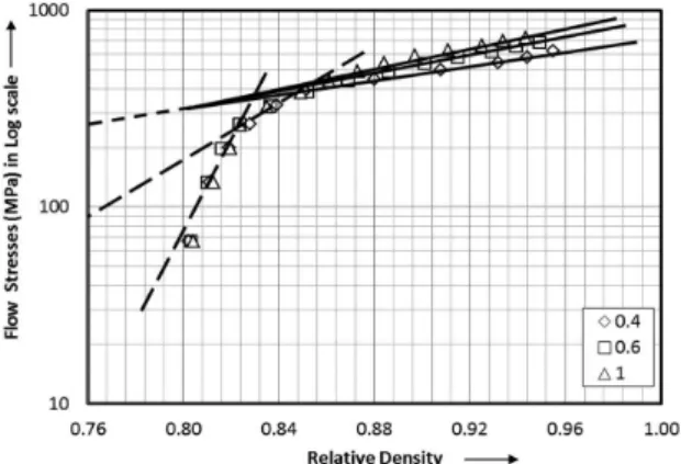
Figure 4 is drawn between stress and strain in log – log scale and Figure 5 is drawn between stress and density in semi-log scale in order to rationalize its mechanism into power law equation. Though the plots (Figures 2, 3) were drawn and characteristic natures have been established in third order polynomial form, it is dificult to control or understand behavior of stress with respect to the inluencing parameter such as strain and density as it is inluenced by four different constants. From Figure 4, the mathematical relationship can be obtained between stress and strain in plastic state that follows as;
load not bring suficient enough to deform the specimen, as its initial pack density was around 80 percent theoretical and initial incremental loads were in the step of 2 tons. The second stage is between 0.06 strain and 0.14 strain, its respective stress fall between 262 MPa and 438 MPa. At this stage there is enough movement of particle, thus a mild retardation in rise of stress. The third stage, there is a continuous enhancement in stress till maximum density is attained or crack appears at free surface; although there is an enhancement in stress, at very slow rate, which predominantly contribute to matrix strain hardening in the specimen. Further observation reveals that lower aspect ratio exhibits higher stress compared to its counterpart; in other words, it can be concluded that decreasing the aspect ratio facilitates uniform deformation which results into quicker strain hardening.
An attempt has been made to relate low stress as a function of density attained during deformation with the effect of aspect ratio in it, thus a plot has been drawn and is shown in Figure 3. Metal specimen subjected to cold plastic deformation results into jamming of grains and so to induce further deformation requires higher stresses, which is termed as matrix work hardening. This behavior is usual for ingot metallurgical products, whereas in powder metallurgical products, apart from a similar matrix strain hardening phenomena it also undergoes geometric work hardening phenomena. Thus, Figure 3 plays an important role to rationalize this concept; density rise, in other words closure of porosities leads to changes in effective volume of the preform, which is the consequence for geometric work hardening. It can be observed that despite density increment, low stress also increases irrespective of aspect ratios, however a curve itting technique is employed and it is found to be as third order polynomial with regression coeficient of unity. This helps to reveal its nature of characteristics to follow three different trend, respectively irst stage between 0.8 and 0.82 relative density; second stage between 0.82 and 0.856 relative density and inal stage from 0.856 to maximum density attained. The interesting point to note is that the irst stage terminates at 262 MPa, and the second stage, although the stress value differs with aspect ratios, it can be approximated to 416 MPa low stress. A very similar behavior has been observed in Figure 2 as well. Therefore, it can be irmly concluded that the copper alloy preform when subjected to cold upsetting, initially shows a peak rise in low stress followed by a retardation in stress rise and inally there is an enhancement in low stress but at very slow pace. Further observation proves that till stage 2, the inluence of aspect ratios is negligible for all the practical considerations, in other words only at the inal stage, the effect of preform geometry or aspect ratios are clearly evident. As opposed to Figure 2, Figure 3 exhibits that decreasing aspect ratio decreases the stress value for any given attained density, especially at the inal stage. This is because higher effective volume requires higher load to deform and subsequently close the porosities, thus for any attained density higher aspect ratios needs higher load or stress to close its internal voids, which predominantly contributes to geometric work hardening behavior.
Figure 3. Characteristics of low stress as a function of relative
density.
Figure 4. Characteristics of low stress as a function of true axial
strain in log-log scale.
Figure 5. Characteristics of low stress as a function of relative
established single mechanism; the relationship obtained is shown in Equation 1,
Now, differentiating Equation 1 with respect to strain,
ε, gives as;
− σ
= ε
ε
(n1)
d Kn
d (8)
Reducing Equation 8, results into;
σ σ
=
ε ε
d n
d (9)
where, n is empirical constant found to be 0.59, from Figure 2; and, σ
ε d
d is work hardening rate.
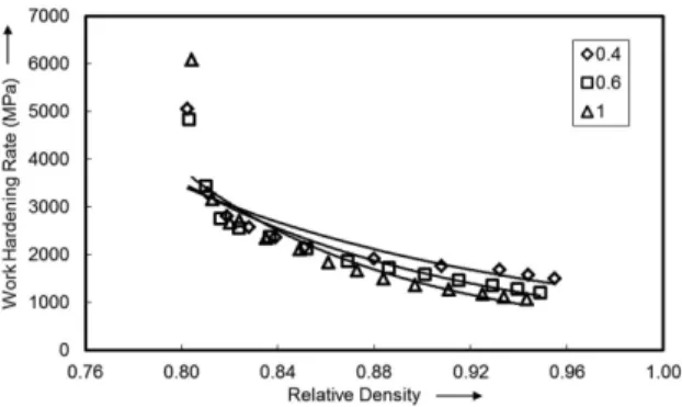
Using Equation 9, the work hardening rate can be obtained for various strain values, and a plot is constructed between these two parameters including the effect of aspect ratios, which is shown in Figure 6. The characteristic nature follows a power law relationship, in other words it follows a 80:20 rule; meaning thereby 80% of effect is due to 20% of cause. During the initial stage, say from 0.00 to 0.14 true axial strains, copper alloy preform exhibits higher work hardening rate, however the span of strain inducement is relatively low. Further it is observed that the rate at which work hardening falls down is also high during this stage. This can be due to the material that consist relatively higher amount of porosities, hence unable to bear resistance against deformation. Yet, this can contribute to more for geometric work hardening than for matrix work hardening in the sintered PM preform. This behavior can be further be ascertained by observing a plot between work hardening rate and density shown in Figure 7. That is from 0.80 to around 0.83 relative densities, there is a drastic decrease in work hardening rate due to closure of pores during deformation. However in the later stage, that is after 0.14 strain till to the end, the effect of work hardening rate is found to be qualitatively 20% despite strain applied could be 80%. This reveals that very slow change in the work hardening rate occurs irrespective of aspect ratios with relatively large amount of strain induced. At this stage the work hardening is much due to matrix than geometric, which can further be proved by establishing relationship between work hardening rate and relative density shown in Figure 7. That is from 0.83 to approximately 0.96 relative densities (relatively 80%),
n
K
σ = ε (1)
where, σ is low stress; ε is true axial strain; K and n are strength coeficient and hardening exponent due to strain respectively. It was obtained that empirical constants, K and
n were respectively found to be as 25 MPa and 0.59. Further interesting observation in Figure 4 is that invariably for all aspect ratio, low stress follows single mechanism against strain, thus an empirical relationship can be established as,
0.59
25
σ = ε , for sintered copper alloy preforms. Therefore, it can be concluded that inducing axial strain the copper alloy preform gradually enhances the low stress irrespective of preform geometry.
In Figure 5, low stresses are in log scale whilst density is in ordinary scale since the density points are not much dispersed, therefore it’s mathematical relationship can be formulated in a following manner;
A straight line equation can be formed from Figure 5 as
σ = +
log mR logC (2)
Equation 2 can be rearranged as
(
σ/)
=log C mR (3)
taking exponential, e on both sides of Equation 3 and further reducing will yield as,
σ =CemR (4)
where, R = (ρf/ρth), R is density ratio; ρf is forged density;
ρth is theoretical density of copper alloy; C and m are respectively strength coeficient and hardening exponent due to densiication.
It can be observed in Figure 5 that initial relative density from 0.80 to 0.85, flow stress follows two different mechanisms; however the inluence of aspect ratio is practically negligible. As it was observed that characteristically all the aspect ratios follow identical mechanism during these stages and its densiication span is relatively smaller, this can be neglected for all practical purpose. Thus the interest is shown for third mechanism, where the trend is different for different aspect ratios and so it’s empirical relationship follows as;
σ =263e2.48R for aspect ratio 1.0 (5)
σ =263e2.23R for aspect ratio 0.6 (6)
σ =263e1.83R for aspect ratio 0.4 (7)
Although the value of C, for all aspect ratios remain constant, the slope, m differs. This clearly proves that smaller the ‘m’ value, slower the rate of resistance to deformation for a given relative density. In other words, increasing the aspect ratio in general increases the low stress at any attained density in the copper alloy preforms.
3.2.
Work hardening rate characteristics
An attempt was made to determine work hardening rate and establish its relationship as a function of true axial strain
more due to matrix than geometric in nature. Further, it is observed that the lower the aspect ratio, higher the work hardening rate for any given relative density.
3.3.
Work hardening rate – statistical analysis
Dverall, it has been delineated that work hardening is due to strain induced and porosity closed or density enhanced, which in certain proportion add to matrix and geometric hardening. The statistical techniques can be used to identify the contribution of these two factors in the presence of three different aspect ratios. Thus analysis of variance (ANDVA) and F-test has been carried out in the experimental data. The four different random sampling variables has been chosen for relative density and axial strain of three different aspect ratios, however to represent the true behaviour of a lot, equally distributed values are opted. Megastat software has been used to carry out ANDVA exercise and the result of it is depicted in Table 1, 2.
The notations used in the tables are expressed and is explained elsewhere17
=
=∑ 1
n i i
ss X (10)
where, ss is sum of squares due to the total variation, Xi is value of considered parameter, n is the sample size.
= −1
df n (11)
=SS MS
df (12)
where, df is the degrees of freedom, MS is mean square or variance and F is the Test-F value that can be calculated by, (MS/MSE) where, MSE is the mean square error.
Since the analysis was considered for a level of signiicance of 5%, the Fα value has been taken to 5%, this is a critical value obtained from F distribution table18.
This value represents a level of conidence up to 95%. Dbservation of both the tables reveals that the ‘F value’ found to be greater than ‘Fα value’, which conirms that
the considered variables are of statistical and physical signiicance. Generally, greater the F value is, the greater the effect on work hardening rate. The last column of these tables is the contribution of variables in percentage. It can be clearly observed that axial strain is greatly contributing to work-hardening rate with nil inluence of aspect ratios. the effect on work-hardening rate is very low (relatively
20%), this is due to gradual closure of pores. Since the pores closure are very gradual unlike in the irst stage this reveals strain inducement is more uniform throughout the preform; particles as well as pores both move at equal pace in the direction of deformation resulting into pore closure as well as work hardening. This is the reason work hardening rate gradually decreases against relative density.
In order to establish the true behavior for work hardening rate against true axial strain and relative density, the parameters are expressed in log scale. Figure 8 is drawn between work hardening rate and true axial strain with inluence of aspect ratio in log-log scale. It can be observed that there is practically nil inluence by the aspect ratio, and a similar observation had been found in Figure 4. Although low stress gradually increases over true strain (in Figure 4), the rate at which work hardening has been induced in the preform is decreasing due to continuous closure of pores or enhancement of density (Figures 7, 9). Figure 9 has been drawn between work hardening rate and relative density in semi-log scale. As observed in Figure 7, from 0.8 to 0.83 relative density range, the work hardening rate drastically reduces; in addition it is observed that there is a nil effect of aspect ratio during this stage. Although density is of short span, this reveals that more of hardening is due to geometric in nature. However, the later stage (0.83 to approximately 0.96 relative density) shows a gradual decrease in work hardening rate against density that ascertains hardening is
Figure 7. Characteristics of work hardening rate as a function of relative density.
Figure 8. Characteristics of work hardening rate as a function of axial strain in log-log scale.
Table 2. Randomized ANDVA of aspect ratio and true axial strain on work hardening rate.
Parameter SS df MS F Fα=0.5% %C
Aspect Ratio 29,388.85 2 14,694.43 9.89 3.98 0.87
True Axial Strain 3,340,890.65 3 1,113,630.22 749.46 3.59 98.87
Error 8,915.49 6 1,485.91 0.26
Total 3,379,194.99 11 100.00
Table 1. Randomized ANDVA of aspect ratio and relative density on work hardening rate.
Parameter SS df MS F Fα=0.5% %C
Aspect Ratio 323,750.00 2 161,875.00 4.85 3.98 8.23
Relative Density 3,411,091.67 3 1,137,030.56 34.08 3.59 86.69
Error 200,183.33 6 33,363.89 5.09
Total 3,935,025.00 11 100.00
The effect of aspect ratios along with relative density and axial strain on work-hardening rate has been shown in Figure 10a, b, which has been obtained from statistical analysis. General observation of these igures reveals that irrespective of variables considered such as density and strain, increasing aspect ratio decreases work hardening rate. This effect is particularly pronounced at higher strain and density range. However the rate of decrease in work hardening is relatively higher when density is considered comparing to axial strain.
4. Conclusions
The present investigation leads to the following major conclusions:
• Empirical relationship has been obtained for low stress against strain and density, in which the effect of aspect ratio is also embedded. It was found that low stress increases by increasing strain and density. However aspect ratio has nil impact when strain is considered; whereas against density, increasing aspect ratio increases low stress.
• Overall, work-hardening rate decreases while increasing strain and density irrespective of aspect ratio considered, but at initial stage this effect is quite drastic followed by a very gradual decrease. Therefore, it is found that initial stage of deformation and densification are much contributed towards geometric work-hardening, whilst later stage is much for matrix work-hardening;
• Statistical analysis revealed the significance of material parameter such as strain induced and density attained on work-hardening rate, as well as the level of contribution by each parameter in percentage.
Dn the other hand, though relative density is contributing signiicant amount for work hardening rate, there is an evidence of aspect ratio inluence too. Further it is observed that there is a little amount of error contribution which is due to the interaction and noise effect.
10. Lei S, Zhang JY, Niu JJ, Liu G, Zhang X and Sun J. Intrinsic size-controlled strain hardening behavior of nanolayered Cu/Zr micropillars. Scripta Materialia. 2012; 66(9):706-709. http:// dx.doi.org/10.1016/j.scriptamat.2011.12.032
11. Narayanasamy R, Anandakrishnan V and Pandey KS. Effect of geometric work-hardening and matrix work-hardening on workability and densification of aluminium-3.5% alumina composite during cold upsetting. Materials &
Design. 2008; 29(8):1582-1599. http://dx.doi.org/10.1016/j.
matdes.2007.11.006
12. Venugopal P, Annamalai S, Jagannathan V and Venkatramani V. Dn the apparent strength-coefficient, strain-hardening exponent and boundary-friction coefficient of sintered P/M copper compacts. Journal of Mechanical Working
Te c h n o l o g y. 1 9 8 7 ; 1 4 ( 2 ) : 1 3 7 - 1 4 7 . h t t p : / / d x . d o i .
org/10.1016/0378-3804(87)90056-8
13. Rajeshkannan A and Narayan S. Strain hardening behaviour in sintered Fe-0.8%C-1.0%Si-0.8%Cu powder metallurgy preform during cold upsetting. Proceedings of the Institution
of Mechanical Engineers - Part B: Journal of Engineering
Manufacture. 2009; 223:1567-1574. http://dx.doi. org/10.1243/09544054JEM1587
14. Selvakumar N, Radha P, Narayanasamy R and Ganesan P. Neural network model for predicting strain hardening and densification constants of sintered aluminium performs.
Powder Metallurgy. 2004; 47(3):261-266. http://dx.doi.
org/10.1179/003258904225020800
15. Balakrishnan R and Thiyagrajan S. A study of the flow properties of aluminium alloys. Journal for Manufacturing
ScienceandProduction. 2012; 12(2):81-86.
16. Selvakumar N, Mohan Raj AP and Narayanasamy R. Experimental investigation on workability and strain hardening behaviour of Fe-C-0.5Mn sintered composites. Materials
& Design. 2012; 41:349-357. http://dx.doi.org/10.1016/j.
matdes.2012.04.053
17. Montgomery DC, Runger GC, Hubele NF. Engineering
statistics. 5th ed. Asia: Wiley; 2012. p. 285.
18. Walck C. Handbook on statistical distributions for
experimentalists. 2007. p. 175. Available from: http://www.
stat.rice.edu/~dobelman/textiles/DistributionsHandbook.pdf. Access in: 01/07/2013.
References
1. Narayanasamy R, Anandakrishnan V and Pandey KS. Effect of carbon content on instantaneous strain-hardening behavior of powder metallurgy steels. Materials Science and
Engineering A.2008; 497:505-511. http://dx.doi.org/10.1016/j.
msea.2008.07.053
2. Chandramouli R, Kandavel TK, Shanmugasundaram D and
Ashokkumar T. Deformation, densiication and corrosion
studies of sintered powder metallurgy plain carbon steel preforms. Materials & Design.2007; 28(7):2260-2264. http:// dx.doi.org/10.1016/j.matdes.2006.05.018
3. Xue L. Constitutive modeling of void shearing effect in ductile fracture of porous materials. Engineering Fracture
Mechanics. 2008; 75(11):3343-3366. http://dx.doi.
org/10.1016/j.engfracmech.2007.07.022
4. Alexandrov S and Lyamina E. Ductile fracture in metal forming: a review of selected issues. Key Engineering
Materials. 2012; 528:1-11. http://dx.doi.org/10.4028/www.
scientiic.net/KEM.528.1
5. Kim J, Zhang G and Gao X. Modeling of ductile fracture:
application of the mechanism based concepts. International
Journal of Solids and Structures. 2007; 44(6):1844-1862. http://
dx.doi.org/10.1016/j.ijsolstr.2006.08.028
6. Rajeshkannan A, Pandey KS, Shanmugam S, Narayanasamy R and Narayan S. Some studies on sintered cold deformed plain carbon alloy steels. Materials & Design. 2012; 33:115-120. http://dx.doi.org/10.1016/j.matdes.2011.07.020
7. Straffelini G and Fontanari V. Stress state dependent
fracture behavior of porous PM steels. Engineering Fracture
Mechanics. 2011; 78(6):1067-1076. http://dx.doi.org/10.1016/j.
engfracmech.2010.12.009
8. Bompard Ph, Wei D, Guennouni G and Francois D. Mechanical and fracture behaviour of porous materials. Engineering
Fracture Mechanics. 1987; 28(5-6):627-642. http://dx.doi.
org/10.1016/0013-7944(87)90058-0
9. Satsangi PS, Sharma PC and Prakash R. An elastic – plastic inite element method for the analysis of powder metal forging. Journal
of Materials Processing Technology. 2003; 136(1-3):80-87.