INFLUENCE OF CROSS SECTION GEOMETRY ON THE
CONFINEMENT OF REINFORCED CONCRETE COLUMNS WITH
CFRP COMPOSITES
Raquel F. Paula
1STAP, Rua Marquês da Fronteira, n.º 8, 3.º dto, 1070-296 Lisboa, Portugal
Manuel G. Silva
2Universidade Nova de Lisboa, Departamento de Engenharia Civil, Quinta da Torre, 2825-114 Monte da Caparica, Portugal
João Vinagre
2Escola Superior de Tecnologia do Barreiro, Dep. de Engenharia Civil,
Rua Stinville, n.º 14, Parque Empresarial do Barreiro, Quimiparque, 2830-144 BARREIRO, Portugal
ABSTRACT
Confinement effectiveness of externally bonded FRP jackets depends on different parameters namely type of concrete, steel reinforcement, FRP jacket stiffness (type of FRP, number of plies and design of wrap), shape of cross section, radius of corners for non-circular sections, and loading conditions. In order to investigate the effect of some of these parameters on the axial behavior of columns under compression and to quantify the level of confinement exerted on the concrete core, an experimental program has been developed.
The experimental research consisted of a sequence of axial compressive tests on cylinders and square prisms. Prisms were divided into three representative groups: sharp-edged sections and sections with rounded corners with corner radii equal to either 20mm or 38mm. The results presented in this paper are for the columns which were wrapped with two plies of unidirectional carbon fibers.
1. INTRODUCTION
Previous experiments have shown that the shape of cross sections of columns can directly affect the confinement effectiveness of externally bonded FRP jackets. As expected, confined prismatic concrete specimens exhibit smaller increases of strength than their cylindrical counterparts, due to the distribution of confining pressure in circular and square or
rectangular sections. Whereas in a circular column all of the section is fully confined, for sharp edged square sections the confining pressure varies from the corners to the centre of the flat, preventing the FRP jacket from providing full confinement.
Some FRP jackets rupture may prematurely occur at the corners of the sharp-edged sections before significant confinement is afforded. This weakness is especially evident for CFRP wraps. The mitigation of this shape effect can be achieved by rounding the corners of the square or rectangular sections. In general, as the corner radius increases, the stress concentration at the edges decreases and the confining pressure becomes more uniform.
Another variable that must be taken into account is the jacket stiffness because the confining action depends on the interaction between the lateral dilation of the concrete and the confining agent. The key parameters to quantify the level of confinement exerted on the concrete core are, thus, the type of FRP, the number of plies of the bonded jacket and, for non-circular sections, the radius of the corners.
In order to investigate the effect of these parameters on the axial compressive behavior of the columns, a test program was established. A series of reinforced concrete cylinders and square prisms specimens of 0.75m height was tested under monotonic axial compression. The prisms were divided into 3 representative groups: R1 - sharp-edged square section of 0.15m width; R2 - square section with corner radius equal to 20mm; R3 - square section with corner radius equal to 38mm, which corresponds to ¼ of the width of the square section. Two types of FRP materials have been utilized in the program: carbon and aramid (Kevlar) fibers, both with high tensile characteristics. Apart from the reference specimens, half of the columns were wrapped with unidirectional carbon fibers and the other half with Kevlar fibers.
Carbon fibers have been more commonly applied to reinforce concrete structures, whereas aramid fibers have also proven to be adequate for column confinement, especially to wrap columns with sharp corners. Moreover, the specific properties of aramid fibers (damage tolerance, impact energy absorbance and anti-ballistic properties) make them a more suitable material for certain applications such as to resist vehicle impact on bridge supports or as blast reinforcement of masonry walls (Pinzelli, 1999).
Stress-strain responses of the CFRP confined concrete specimens tested are shown. The increase in axial strength for circular and square sections with rounded corners is compared, as well as their deformation capacity.
Experimental results are reported and analyzed in terms of the parameters that characterize the compressive behavior of confined concrete. Confinement effectiveness, evaluated by means of the stress-strain response, the increase of compressive concrete strength and strain and the CFRP strain, was found to be function of the geometry of cross section.
2. EXPERIMENTAL PROGRAM DETAILS 2.1 Materials
In order to investigate the effects of cross section geometry and type of FRP on the axial compression behavior of concrete columns confined with FRP jackets, an experimental program was established, which consisted of a series of circular and square reinforced concrete specimens of 0.75m height.
Firstly, six 150mm diameter circular specimens and six 150mm width sharp-edged square specimens, with and without CFRP jackets, were tested. Following these tests, the effect of rounding the corners of the square specimens was studied by testing 3 square specimens with corner radii equal to 20mm (R2-square) and other 3 with corner radii equal to
38mm (R3-square), which corresponds to ¼ of the width of the square section. The radii of the corners were guaranteed by means of the formwork.
All of the square specimens have the same gross cross sectional area. The longitudinal and transverse reinforcing steel were kept constant for all the column specimens. Apart from the reference specimens, half of the columns were wrapped with 2 plies of carbon unidirectional fibers and the other half with 2 plies of Kevlar fibers. The fibers were applied to the whole height of the columns and oriented in its transverse direction.
The CFRP wrap presented high flexibility (which permitted very good fitting to the geometry of cross sections) and the design thickness indicated by the manufacturer was equal to 0.176mm.
The tensile properties of the CFRP material used in this study are shown in Table 1. The experimental values were determined as per ASTM D3039 tensile coupon tests. CFRP materials exhibited linear-elastic behavior up to failure.
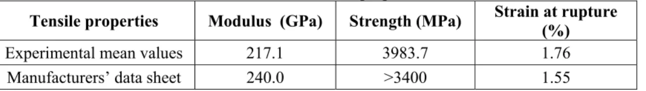
Table 1 - CFRP tensile properties
Tensile properties Modulus (GPa) Strength (MPa) Strain at rupture (%)
Experimental mean values 217.1 3983.7 1.76
Manufacturers’ data sheet 240.0 >3400 1.55
2.2 Specimen instrumentation
All specimens were tested under a concentric axial load test. Two or three linear variable displacement transducers (LVDTs) were used to measure axial strains. Transverse strains in the jackets were measured with an array of strain gauges on the outer surface and at the mid height of the specimens.
3. EXPERIMENTAL RESULTS (Effects of Cross Section Geometry) 3.1 Stress-Strain diagrams
The results presented in this paper are for the CFRP wrapped columns. Results obtained showed that stress-strain response of CFRP confined concrete specimens is bilinear, with the second slope being function of the parameter R/D (R – radius of the corners; D - section width). Variation of hoop stresses at mid height of specimens was measured on several gauges bonded to the jacket: in the composite wrap they vary around the perimeter of the section, unlike the case of circular sections.
Representative compression axial stress-strain curves of the CFRP wrapped specimens are shown in Fig. 1. Failure modes of two specimens are presented in Fig. 2. CFRP confined columns exhibited greater strength and ductility to that of unjacketed control specimens, as expected. The effects of cross section shape on the effectiveness of the confinement of the FRP jacketed columns is evident from the curves shown in Fig. 1.
The curves of the CFRP confined concrete are bilinear with a transition zone, except in the case of the sharp edge columns. The elastic slope (initial elastic zone with initial rigidity equal to E1) is not substantially altered with confinement, as it is identical to that of the unconfined concrete. The transition zone occurs shortly after the peak strength of the unconfined concrete (reference specimens) has been reached. The plastic rigidity (E2) is function of the geometry of cross section.
As expected, the strength of confined columns is higher for circular sections than for square ones. Also, efficiency of CFRP confinement of square columns increases with decreasing corner sharpness.
0 10 20 30 40 50 60 70 80 90 100 110 0,00 0,20 0,40 0,60 0,80 1,00 1,20 1,40 1,60 1,80 2,00 2,20 2,40 2,60 2,80 3,00
Figure 1 - Effects of geometry cross section on the axial stress-strain curves of CFRP confined columns
Figure 2 – Failure modes of CFRP confined columns
3.2 Lateral Strain / CFRP Strain at Failure
The axial behavior of the confined concrete is closely related to the confining pressure that the FRP jackets exert on the concrete. CFRP strain at rupture of the confined columns is usually lower than the ultimate strain obtained by tensile testing of the CFRP coupons. This
fc (MPa) εc (%) Unconfined concrete Circular E2 = 23.7GPa Square R3=38mm E2 = 15.3GPa Square R2=20mm E2 = 5.0GPa Sharp edges, R1 E2 ≈ 0GPa
reduction is due to several reasons, including the curved shape of the CFRP wrap, especially at corners with low radius (Davol, 1998).
For the CFRP wrapped cylinders, the maximum lateral strain obtained was equal to 1.45%, which is lower than the CFRP tensile strength. Unlike those in the circular sections, the lateral stresses in the square specimens vary around the section. Plots showing the variation of the CFRP strain (lateral strain) along the perimeter of flat sections have been obtained for each square specimen but they are not presented here for brevity. The evolution of the CFRP strain was plotted against concrete axial stress-strain, at selected points of the perimeter of the section where the gauges were glued to the CFRP.
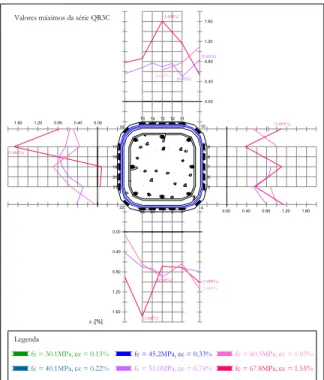
Figures 3 and 4 show the maximum values of CFRP strain obtained along the flat sections of R2 and R3 rounded square specimen. The maximum values of the CFRP strain are plotted against the ultimate values of stress and strain in concrete at specimen failure. For each flat side of the square specimen, maximum values of CFRP strain occurred at the start of the curved segment.
0.80 1.40 1.00 1.60 ε j [%] 1.80 1.20 fc = 30.0MPa, εc = 0.18% fc = 40.1MPa, εc = 0.58% Legenda (1.377%) fc = 45.0MPa, εc = 1.47% fc = 50.3MPa, εc = 2.65% (1.003%) 15 23 1.60 1.20 0.80 0.40 0.00 -0.20 0.60 0.20 (0.845%) 16 21 20 19 18 17 22 0.40 0.00 1.80 1.60 1.40 1.20 1.00 0.80 0.40 0.60 0.20 0.00 -0.20 1.60 1.20 0.80 0.40 0.00 10 11 12 13 14 (1.631%) 9 8 7 6 24 5 4 3 2 1
Valores máximos da série QR2C
Figure 3 – CFRP strain at failure along the perimeter of R2 cross sections For some specimen, after the initial elastic phase, the outer ply of the fibers started to debond at the end zone of overlapping. The gauges bonded in that zone denoted this phenomenon, as the CFRP extension decreased and reached negative values (compression). Observation of the specimens after the tests permitted to verify that the rupture of the fibers occurred at the start of the curved segment and to observe the curvature of the longitudinal bars between stirrups.
Maximum CFRP strains along the perimeter of the square sections are shown in Table 2. Generally, the maximum tensile strain occurred at the center of the flat or near the start of the radius for the specimens with rounded corners. It has been referred that as the concrete expands the flat sides bulge out and the final section resembles a circular section as the loading progresses. This deformed section is better able to resist further expansion than the original geometry (Davol, 1998). The rupture of the specimen QR3C2 corresponded to a
maximum extension of the CFRP of 1.63% (gauge 5), which corresponds to a tensile stress of 3729.4MPa, i. e., about 88.8% of its tensile strength.
For the sharp edged sections, the maximum CFRP strains occurred near the corners and did not engage CFRP tensile tested capacity. CFRP strain values of the sharp-edged confined columns indicate that the confining mechanism has not been fully activated. Typical shape of the stress-strain curves of sharp-edged CFRP confined columns indicates that the geometry of cross section does not allow the CFRP wrap to develop sufficient confining pressure to overcome the effect of the degradation of the concrete under the large strains it experiences after the initial elastic zone.
0.00 ε j[%] fc = 30.1MPa, εc = 0.13% fc = 40.1MPa, εc = 0.22% Legenda 1.60 1.20 0.80 0.40 fc = 60.3MPa, εc = 1.03% fc = 67.8MPa, εc = 1.55% fc = 45.2MPa, εc = 0.33% fc = 55.0MPa, εc = 0.74% 1.60 1.20 1.60 1.20 0.80 0.40 0.00 1.20 0.80 0.40 0.00 3 16 (0.50%) (0.83%) 1514131211 10 17 18 19 20 21 9 8 7 6 5 22 4 2324 2 0.80 0.40 0.00 1 1.60 (1.608%) (1.683%) (1.682%) (1.008%) (0.627%) (1.092%) (1.140%) (0.905%) Valores máximos da série QR3C
Figure 4 – CFRP strain at failure along the perimeter of R3 cross sections
Table 2 - Variation of CFRP strain around the perimeter of square sections Maximum CFRP strain (%)
Series Specimens
Center of flat side 15mm from the corner
QR1C1 0.851 1.151
QR1C2 0.249 0.389 Sharp-edged
QR1C3 0.107 0.155
Center of flat Start of curve Corner
QR2C1 0.960 1.631 0.960 QR2C2 1.250 1.113 1.110 R2-Square QR2C3 1.581 1.017 0.914 QR3C1 0.870 0.718 0.833 QR3C2 1.608 1.683 1.008 R3-Square
3.3 Dilation Ratio of Concrete
Unconfined concrete under axial compression is often assumed to have a constant value of the dilation ratio, µ (which is defined as the ratio of the transverse strain in the concrete (εt) to the axial strain (εc)), equal to Poisson’s ratio for concrete (about 0,2), up to an
axial stress level of about 70% of the unconfined compressive strength of concrete (fco). For
levels of stress between 0,7fco e fco, the dilation ratio increases rapidly to a value of about 0,5
(Chen, 1982).
For confined concrete, as the compression stress nears the value of the unconfined compressive strength of concrete, it is no longer possible to use the Poisson’s ratio to represent the ratio of the of the transverse strain in the concrete to the axial strain due to general concrete cracking.
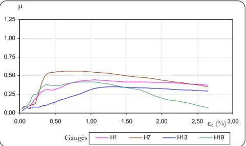
Concrete confined with a linear elastic material will be subjected to an increasing lateral confining pressure, owing to the increasing of the lateral strain. Smaller dilation ratios allow larger axial deformations to take place before failure of the jacket material occurs. Figures 5 to 7 illustrate this effect for the circular and square specimens confined with CFRP (lateral strains of the square specimens correspond to the values obtained from the gauges at the center of the flats).
0,00 0,25 0,50 0,75 1,00 1,25 0,00 0,50 1,00 1,50 2,00 2,50 3,00 Figure 5 - Dilation ratio of circular CFRP confined concrete
For both circular and square specimens, dilation ratio varies between 0,17 and 0,20 for axial strains up to 0,2%. This initial dilation ratio may be smaller than the Poisson’s ratio for concrete confined with a very stiff jacket (Spoelstra, 1999). Beyond axial strains of 0,2%, the dilation ration increases rapidly to a maximum value (µmáx), and then decreases slightly and remains relatively constant until rupture of concrete. Dilation ratios of the circular and R3-square sections are higher than the R2-R3-square sections and the sharp-edged ones.
εc (%)
µ
C2
C3 C1
0,00 0,25 0,50 0,75 1,00 1,25 0,00 0,50 1,00 1,50 2,00 2,50 3,00 H1 H5 H9 H13
Figure 6 - Dilation ratio of R3-square CFRP confined concrete
0,00 0,25 0,50 0,75 1,00 1,25 0,00 0,50 1,00 1,50 2,00 2,50 3,00 H1 H7 H13 H19
Figure 7 - Dilation ratio of R2-square CFRP confined concrete 3.4 Verification of equations
Several models that evaluate the FRP confined concrete properties have been assessed against the experimental database presented in this paper. Some of the existing models have been found to match experimental results more closely than others. The theoretical entire stress-strain diagrams of the FRP confined concrete columns are plotted against the experimental data elsewhere (Paula, 2001).
Generally heavily confinement of FRP circular sections are due the uniform lateral confining pressure resulting from tensile hoop stress in the FRP wrap. On the other hand, in the case of square cross sections, the lateral confining pressures are not uniform.
Most of the existing models have been applied to cylindrical sections. To predict the FRP confined properties of concrete square sections, an effective lateral confining pressure was determined by introducing a confinement effectiveness coefficient (k), which is obtained
Gauges εc (%) µ εc (%) µ Gauges
by considering the ratio Ae/Ac, where Ae is the area of effectively confined concrete core and
Ac is the area of concrete (gross cross-sectional area minus area of longitudinal steel reinforcement). For a square section, ke takes into account the radius of the corners and is
given by Equation 1, where b is the width of the square section and R is the radius of corners:
(
)
ge b R A
k =1−2 −2 2/3 (1)
4. CONCLUSIONS
Uniaxial compression tests on RC columns confined with CFRP jackets have shown that the increase of ultimate strength is highly influenced and increases with the radius of the corners of square sections. On the other hand, the increase of axial deformation capacity is up to 8 times that of unconfined concrete, even for the sharp edged sections.
Further investigation is required in order to accurate models capable of predicting actual behavior of FRP confined concrete including geometric parameters need to be included in equations.
Experimental work on jackets made with aramid fibers are expected to shed further light on alternatives that mitigate problems caused by sharp edges of columns.
5. ACKNOWLEDGES
The authors are grateful to Mr. José Gaspar and Eng.º Alexandre Paulo for their precious help with the lab experiments. Special thanks are due to Professor Carlos Rodrigues for his contribution to the execution of the experimental testing setup. The Portuguese Foundation for Science and Technology provided support for this study under PRAXIS XXI Project CEG 3/3.1/2572-95.
6. REFERENCES
ASTM D3039, Standard test method for tensile properties of polymer matrix composite materials, ASTM Vol. 14.02 (1995).
Chen, W., Plasticity in Reinforced Concrete, Mc-Graw-Hill Book Company (1982). Davol, A., Structural characterization of concrete filled fiber reinforced shells, University of California, San Diego (1998).
Paula, Raquel F., Influência da geometria das secções no confinamento de pilares de betão armado com compósitos de CFRP, Instituto Superior Técnico (2002).
Pinzelli, R., The contribution and role of aramid fibre for external strengthening and repairs of concrete structures, Structural Faults & Repair 99 Conference.
Spoelstra, M.R., Monti G., FRP-Confined concrete model, Journal of Composites for Construction, ASCE, 3, p. 143-150 (1999).