UNIVERSIDADE DA BEIRA INTERIOR
Engenharia
Optimization
of Spectrum Management in Massive
Array
Antenna Systems with MIMO
(versão final após defesa)
Rooderson Martines de Andrade
Dissertação para obtenção do Grau de Mestre em
Engenharia Eletrotecnica e Computadores
(2º ciclo de estudos)
Orientador: Prof. Doctor Fernando J. Velez
I would like to dedicate this thesis to all my family and especially my wife, Fernanda Cálida, who was present throughout this journey
Acknowledgements
First of all, I want to thank God for the gift of life and for giving me health and preserving the ability to carry out this work, leading to a successful conclusion in a journey of learning and enrichment that was undoubtedly the best academic experience that I had in all my University course. I would also like to thank especially those who participate in my journey, without whom it would not even have been possible to begin my academic life: my parents Rooderson Santos de Andrade and Fátima Oliveira Martines de Andrade, my brothers Mario Andrette, Fábio Rene, Thayrine Andrade, my sister-in-law Nadia, Rochele, brother-in-law Aricleiton and especially my ”wife Fernanda Cálida”, because without the unconditional support, and for accompanying me on this long journey that for a long time may have been a challenging journey, and yet she was always to my side and always supporting me, being my safe harbor. Thank you for all the support and for your love that I take with me every day. To my friends that I made during this period in Portugal. To all of them I undoubtedly owe my most sincere thanks for being a family to me all the time, for your prayers and fatigue for my sake. I always pray for all of you. To my adviser Dr. Fernando José Velez, for all his dedication, for all his patience and for helping me and leading throughout this journey. Area that I discovered thanks to him and in which I discovered the fascinating universe of technology and science where I am and want to continue working and growing in my professional life. To thank all the friends I made during this battle, the first friend of Bruno Cruz I had in Portugal, a Portuguese brother who helped me in many moments. The friends of the PAC, Matheus, Francisco, Giuseppe, Henrique, Manuela, Emanuel, Emanuel Teixeira, Cristino and Anderson, who in their way helped me during this journey with support and insentience, are friends that I will remember forever. I thank all the teachers who participated in my education as a future Master. And finally, I wanted to thank God again for all the means he used and arranged so that I could study and get to this point where I intend to obtain a degree Master’s in Electrical Engineering and Computers. I would especially like to thank the Instituto de Telecomunicações for the opportunity to carry out my research and for the scholarship supported by National Funding from the FCT - Fundação para a Ciência e a Tecnologia, through UID/EEA/50008/2013 and the equipment that was made available for the laboratory work by ORCIP, the support from COST CA 15104 IRACON, ORCIP and CONQUEST (CMU/ECE/0030/2017) have been of fundamental important.
Abstract
Fifth generation (5G), is being considered as a revolutionary technology in the telecommuni-cation domain whose the challenges are mainly to achieve signal quality and great ability to work with free spectrum in the millimetre waves. Besides, other important innovations are the introduction of a more current architecture and the use of multiple antennas in transmission and reception. Digital communication using multiple input and multiple output (MIMO) wireless links has recently emerged as one of the most significant technical advances in modern commu-nications. MIMO technology is able to offer a large increase in the capacity of these systems, without requiring a considerable increase in bandwidth or power required for transmission. This dissertation presents an overview of theoretical concepts of MIMO systems. With such a system a spatial diversity gain can be obtained by using space-time codes, which simultaneously exploit the spatial domain and the time domain. SISO, SIMO and MISO systems are differentiated by their channel capacity and their configuration in relation to the number of antennas in the transmitter/receiver. To verify the effectiveness of the MIMO systems a comparison between the capacity of SISO and MIMO systems has been performed using the Shannon’s principles. In the MIMO system some variations in the number of antennas arrays have been considered, and the superiority of transmission gains of the MIMO systems have been demonstrated. Combined with millimetre waves (mmWaves) technology, massive MIMO systems, where the number of antennas in the base station and the number of users are large, is a promising solution.
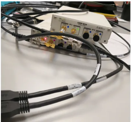
SDR implementations have been performed considering a platform with Matlab code applied to MIMO 2x2 Radio and Universal Software Peripheral Radio (USRP). A detailed study was initially conducted to analyze the architecture of the USRP. Complex structures of MIMO systems can be simplified by using mathematical methods implemented in Matlab for the synchronization of the USRP in the receiver side. SISO transmission and reception techniques have been considered to refine the synchronization (with 16-QAM), thus facilitating the future implementation of the MIMO system. OpenAirInterface has been considered for 4G and 5G implementations of actual mobile radio communication systems. Together with the practical MIMO, this type of solution is the starting point for future hardware building blocks involving massive MIMO systems.
Keywords
Resumo
A quinta geração (5G) está sendo considerada uma tecnologia revolucionária no setor de tele-comunicações, cujos desafios são principalmente a obtenção de qualidade de sinal e grande ca-pacidade de trabalhar com espectro livre nas ondas milimétricas. Além disso, outras inovações importantes são a introdução de uma arquitetura mais atual e o uso de múltiplas antenas em transmissão e recepção. A comunicação digital usando ligaçõe sem fio de múltiplas entradas e múltiplas saídas (MIMO) emergiu recentemente como um dos avanços técnicos mais significativos nas comunicações modernas. A tecnologia MIMO é capaz de oferecer um elevado aumento na capacidade, sem exigir um aumento considerável na largura de banda ou potência transmitida. Esta dissertação apresenta uma visão geral dos conceitos teóricos dos sistemas MIMO. Com esses sistemas, um ganho de diversidade espacial pode ser obtido utilizando códigos espaço-tempo reais. Os sistemas SISO, SIMO e MISO são diferenciados pela capacidade de seus canais e a sua configuração em relação ao número de antenas no emissor/receptor. Para verificar a eficiência dos sistemas MIMO, realizou-se uma comparação entre a capacidade dos sistemas SISO e MIMO utilizado os princípios de Shannon. Nos sistemas MIMO condecideraram-se algumas variações no número de agregados de antenas, e a superioridade dos ganhos de transmissão dos sistemas MIMO foi demonstrada. Combinado com a tecnologia de ondas milimétricas (mmWaves), os sistemas massivos MIMO, onde o número de antenas na estação base e o número de usuários são grandes, são uma solução promissora.
As implementações do SDR foram realizadas considerando uma plataforma com código Matlab aplicado aos rádios MIMO 2x2 e Universal Software Peripheral Radio (USRP). Um estudo detalhado foi inicialmente conduzido para analisar a arquitetura da USRP. Estruturas complexas de sistemas MIMO podem ser simplificadas usando métodos matemáticos implementados no Matlab para a sincronização do USRP no lado do receptor. Consideraram-se técnicas de transmissão e recepção SISO para refinar a sincronização (com 16-QAM), facilitando assim a implementação futura do sistema MIMO . Considerou-se o OpenAirInterface para implementações 4G e 5G de sistemas reais de comunicações móveis. Juntamente com o MIMO na pratica, este tipo de solução é o ponto de partida para futuros blocos de construção de hardware envolvendo sistemas MIMO massivos.
Palavras-chave
Table of Contents
1 Introduction 1
1.1 Motivation . . . 1
1.2 Evolution of Telecommunications Technology . . . 2
1.2.1 First Generation . . . 3
1.2.2 Second Generation . . . 4
1.2.3 Second and a half Generation . . . 4
1.2.4 Third Generation . . . 5
1.2.5 Fourth Generation . . . 6
1.2.6 Fifth Generation . . . 7
1.3 Objectives and Approach . . . 9
1.4 Contributions . . . 10
1.5 Outline of the Dissertation . . . 11
2 Wireless Systems with Multiple Antennas 13 2.1 Introduction . . . 13
2.2 Introduction Multiple Input Multiple Output . . . 13
2.3 Single Input Single Output . . . 14
2.4 Single Input Multiple Output . . . 15
2.5 Multiple Input Single Output . . . 15
2.6 Multiple Input Multiple Output . . . 16
2.7 MIMO Transmission Techniques . . . 17
2.7.1 Diversity . . . 17
2.8 Channel Capacity in MIMO . . . 23
2.8.1 Capacity of Orthogonal Channels . . . 27
2.8.2 Simulation Capability MIMO Channel . . . 28
2.9 Capacity of SIMO and MISO Channel . . . 28
2.10 Beamforming . . . 30
2.11 Conclusions . . . 34
3 Millimetre Wave Communications 37 3.1 Introduction . . . 37
3.2 Millimetre Wave . . . 38
3.2.2 Millimetre wave for 5G future . . . 40
3.3 Millimetre Wave Propagation and Channel Models . . . 42
3.3.1 Distance Based Path Loss . . . 42
3.4 What is Massive MIMO? . . . 43
3.4.1 Channel Estimation . . . 45
3.4.2 Uplink Data Transmission . . . 47
3.4.3 Downlink Data Transmission . . . 47
3.5 Continuous Aperture Phased MIMO . . . 47
3.5.1 Overview of CAP-MIMO . . . 49
3.6 Conclusions . . . 51
4 Implementation of transmitter and receiver with USRP B210 53 4.1 Introduction and Objectives . . . 53
4.2 Description of the work carried out . . . 54
4.3 Hardware Implementation with USRP . . . 56
4.3.1 USRP and its Programming with Matlab . . . 56
4.3.2 Transmitter implemented in USRPs . . . 58
4.3.3 Implementation of the Receiver and Aspects of Synchronization . . . 61
4.3.4 Tests and preliminary experimental results . . . 61
4.4 Testing the connection with NARDA SRM 3006 . . . 64
4.5 Creation of an LTE network with OpenAirInterface . . . 66
4.5.1 OAI Set-up: Connect EPC + eNB with COTS UE . . . 67
4.6 MIMO with USRP . . . 70
4.7 Conclusions . . . 73
5 Conclusions and Future Research 75 5.1 Conclusions . . . 75
5.2 Future activities . . . 77
References 79 A 4G system with OpenAirInterface: Installation and configuration 87 A.1 Overview of OpenAirInterface . . . 87
A.1.1 Requirements for installation . . . 88
A.2 Get the sources . . . 89
A.3 Unitary Simulation of LTE PHY . . . 89
List of Figures
1.1 2G, 3G and 4G network architecture, adapted from [1]. . . 7
1.2 5G network architecture, adapted from [2]. . . 8
1.3 Evolution of mobile communication networks, adapted from [3] . . . 9
2.1 Multiple Input Multiple Output . . . 13
2.2 Single Input Single Output. . . 14
2.3 Single Input Multiple Output. . . 14
2.4 Multiple Input Single Output. . . 14
2.5 Multiple Input Multiple Output. . . 17
2.6 Time diversity, adapted from [4]. . . 18
2.7 Frequency diversity, adapted from [4]. . . 19
2.8 Space time diversity, adapted from [4]. . . 20
2.9 Space frequency diversity, adapted from [4]. . . 20
2.10 Space time block code with diversity space, adapted from [5] . . . 21
2.11 Spatial multiplexing channel matrix adapted from [6] . . . 23
2.12 MIMO Channel, adapted from [7]. . . 24
2.13 MIMO Capacity, according to equations (2.3) and (2.13) . . . 29
2.14 Beamforming . . . 31
2.15 Bemforming with MIMO 6x6 . . . 31
2.16 First Null Beamwidth, adapted from [8] . . . 32
3.1 Millimetre wave spectrum . . . 39
3.2 Massive MIMO . . . 44
3.3 Transmission protocol of TDD Massive MIMO, adapted from [9] . . . 46
3.4 Transmission Protocol of TDD Massive MIMO, adapted from [9] . . . 46
3.5 DLA-based beamfoming CAP-MIMO transceiver, adapted from [10] . . . 48
3.6 Line of Sight Propagation. . . 51
4.1 Overview of the hardware elements . . . 55
4.2 Universal Software Radio Peripheral(USRP) [11] . . . 57
4.3 Architecture USRP-B210 adapted from [11] . . . 57
4.4 USRP connection to the PC via USB cable . . . 59
4.5 Get TX Parameters . . . 59
4.7 USRP Simultaneous connection of antennas for the transmission and reception of
signals . . . 60
4.8 USRP Cable Connection . . . 60
4.9 USRP TX / RX connection . . . 62
4.10 Transmitter signal (TX) . . . 63
4.11 Code for the transmitter Signal . . . 63
4.12 Received Signal . . . 63
4.13 Signal received RX . . . 64
4.14 Transmitter signal at 900 MHz in the Digital Storage Oscilloscope . . . 64
4.15 Comparison between the transmitter signal and the receiver signal at a frequency of 900 MHz . . . 65
4.16 NARDA SRM 3006 . . . 65
4.17 Comparison between the transmitter signal and the receiver signal at a frequency of 1846 MHz . . . 66
4.18 Comparison between the transmitter signal signal at a frequency of 900 MHz . . 66
4.19 USRP B210 and antennas vert900 . . . 68
4.20 OAI scenario: EPC + eNB + COTS UE . . . 68
4.21 Configuration sistema of OpenAirInterface . . . 69
4.22 Interface scope of the UL . . . 69
4.23 Scope of the UL . . . 70
4.24 Signal Transmitter MIMO 2x2 TX . . . 71
4.25 Signal Transmitter MIMO 2x2 TX1 . . . 71
4.26 overlapping of the signals transmitted by the TX1 and TX2 antennas . . . 71
4.27 Signal Received in MIMO 2x2 RX1 . . . 72
4.28 Signal Received in MIMO 2x2 RX2 . . . 72
4.29 Signal Received in MIMO 2x2 RX (overlaped signals) . . . 72
4.30 Configuration of parameters in block USRP RX . . . 73
A.1 Training OpenAirInterface (I) . . . 91
List of Tables
List of Acronyms
1G First Generation 2G Second Generation 3G Third Generation 4G Fourth Generation 5G Fifth Generation AA Array AntennaACI Adjacent Carrier Interference
ADSL Asymmetric Digital Subscriber Line
AMPS Advanced Mobile Phone System
BER Bit Error Rate
BF Beamformer
BS Base Station
BSC Base Station Controller
CAP-MIMO Continuous Aperture Phased Multipl Input Multiple Output
CDMA Code Division Multiple Access
CSI Channel State Information
DFE Decision Feedback Equalizer
DFT Discrete Fourier Transform
EGC Equal Gain Combining
FDM Frequency Division Multiplexing
FDMA Frequency Division Multiple Access
GPRS General Pacet Radio Servisse
GSA Global Mobile Suppliers Association
GSM Global System for Mobile Communications
HPB Half Power Beam
HPBW Half Power Beam Width
HSPA High Speed Packet Access
IB-DFE Iterative Block Decision feedback equalizer IDFT Inverse of Discrete Fourier Transform
IMT2000 International Mobile Telecommunications-2000
IRACON Inclusive Radio Communications
LTE Long Term Evolution
LTE-A LTE- Advanced
MAAS Massive Array Antenna Systems
MIMO Multiple Input Multiple Output
MISO Multiple Input Single Output
mMIMO Massive MIMO
mmRF-HARVESTING Radio Frequency Energy Harvesting
MMSE Minimum Mean Squared Error
mmWave Millimeter Wave
MRC Maximal Ratio Combining
MSE Mean Squared Error
OFDM Orthogonal Frequency-Division Multiplexing
PA Power Amplifier
PLP Physical Layer Pipes
QoS Quality of Service
QPSK Quadrature Phase-Shift Keying
RAN Radio Access Networks
RNC Radio Network Controller
RF chain Radio Frequency Chain
SC Selection Combining
SFBC Space Frequency Block Code
SIMO Single Input Multiple Output
SINR Signal to Interference plus-Noise Ratio
SISO Single Input Single Output
SMS Short Messaging Service
SNR Signal to Noise Ratio
STBC Space Time Block Code
TDD Time Division Duplex
TDMA Time-Division Multiple Access
TD-SCDMA Time Division Synchronous Code Division Multiple Access
TFS Time-Frequency Slicing
TI Time Interleaving
UBI Universidade da Beira Interior
UCA Uniform Circular Array
ULA Uniform Linear Array
UMTS Universal Mobile Telecommunication System
UPA Uniform Planar Array
URA Uniform Rectangular Array
USRP Universal Software Radio Peripherals
UT User Terminal
UTRA Universal Terrestrial Radio Access
V-BLAST Vertical Bell Labs Layered Space-Time WCDMA Wide Band Code Division Multiple Access
WiMAX Worldwide Interoperability for Microwave Access
Wireless-WWW Wireless Word Wide Web
WLAN Wireless Local Area Networks
Chapter 1
Introduction
1.1
Motivation
The potential benefits of increasing by several orders of magnitude the number of antennas used in wireless communications have been theoretically established. However, existing systems fail to deliver on this promise. The research within this Master dissertation considers a combination of two technologies, in order to make the way for Tbit/s wireless communication. In considers antennas with spatial precessing using Multiple Input Multiple Output (MIMO) techniques. It is considered that millimetre wave (mmWave) bands have a wide range of spectra available that allows for fast transmission.
The evolution of wireless communications from analogue to digital led to the enhancement of early propagation models, which provided information about power, in order to also consider time delay information. Further consideration of the space domain either with space diversity or smart antennas or, nowadays, MIMO systems has also pushed the evolution of propagation modeling toward more complex spatial-temporal considerations [7].
Multiple Input Multiple Output (MIMO) is a key technology for a new step in Fifth Generation (5G) systems along with Massive MIMO, which would use large antenna arrays to transmit data to multiple devices within a small cell in the same frequency range. MIMO technology emerges as one of the most efficient in the portability environment, where the signal transmission and reception must be error free in order to avoid damages in communication and data sent. MIMO technology has emerged as one of the techniques that are capable of optimizing transmission channels, ensuring high signal reception quality.
In the low frequency bands it is difficult to reduce the size of the antennas, as well as the complexity of the architecture and AC/DC conversion. However, in upper bands as the millimetre wavebands, it is possible to insert large arrays even in small mobile transmitted in view of the relationship between the size and energy consumption in these physical systems, the study has, as a starting point, developed of mathematical methods to reduce the system complexity, the size and power consumption, further magnifying Massive Array Antenna Systems (MAAS) gain and spatial processing capabilities, matrix for the MAAS.
In MAAS at the mmWave frequency bands, the envisioned solution to overcome hardware and software complexity is to use hybrid analogue-digital transceiver architectures that, together
with the appropriate signal processing and modulation design whilst decreasing the power con-sumption.
The aim of this research is two-fold, to develop and and verify them through simulation and experimental validation, signal processing algorithms at the link-level to provide an increase of the data rates at feasible complexity (precoding and receiving schemes), adequate to the mixed analogue-digital architectures.
The Fifth Generation (5G) technology has had a very broad growth over the last few years, suffering more in some respects, such as bandwidth, energy consumption and the complexity of the architecture, which generates a great financial cost. Considering that 5G technology, compared to its predecessor at Fourth Generation (4G), has a much higher transfer rate coupled with a more efficient transmission, more affected by the limitation of the demand of spectra for transmission and high frequencies, contributing to the application of new applications related to the use of millimetre waves (mmWave), to which using little licensed spectra. Which means that the spectra millimetre waves are available to be used [13],[14].
With increasing frequencies, to use the mmWave parameter where more spectral features are available, the general amplification of Power Amplifiers (PAs) is a problem whose solution makes the architecture much more complex. In order to minimize the complexity of transmission sys-tems on multiple antennas for mmWave syssys-tems, we can adopt the concept of phased array techniques that consists of using several antennas to compost by antennas constructed in mi-crostrip pattern, taking this concept in mind and thus be possible considerably increase the effective aperture of the antennas as can be studied in more detail in [14]. The use of this technique is also being assumed in the context fort of this research.
1.2
Evolution of Telecommunications Technology
Mobile communication has become more popular in recent years due to the rapid overhaul of First Generation (1G) to Fifth Generation (5G) in mobile technology. This reform is due to the requirement of transmission technology compatible with the service and the very high increase of telecommunications customers. Generation refers to change in the nature of the transmission technology compatible with the service and new frequency bands. In the 1980s, the cell phone era began, and since then mobile communications have undergone considerable changes and experienced massive growth. In this , we discuss the evolution of wireless communication from the emergence of 1G to the current 5G, a major breakthrough in mobile communication, since the technologies most used today and the main contributions will be addressed.
1.2.1
First Generation
The input technology in mobile communication systems first appeared in the 1980s, where these types of systems were known as First Generation (1G) the first generation, and used an Advanced Mobile Phone System (AMPS) network technology that was only possible the transmission of voice data. It used an analog system and its speed of transfer was around 9 kbps [15]. Until then, all mobile communication was centralized, thus having low traffic capacity and high cost. Its success was due to the novelty that came up: making phone calls away from home, on a wire-less device, and on the move. Being a new system, little was known about its potential and its acceptance in the market. It is worth remembering that, at the time of the development of this technology, everything that humanity did was done without the use of this system, which could lead many people to think that this might not be so important or that it was not worth the investment cost [16]. For this reason, in the first generation, little effort was made to standard-ize use in all countries. Indeed, a number of standards have been proposed and implemented, in isolation, in just one country. After the consolidation of this generation, it was found that Europe had been divided into standards:
• TACS standard: United Kingdom, Austria, Spain, Ireland, Italy; • NMT450: Sweden, Norway, Finland, Denmark;
• Radiocom2000: France.
The AMPS system was frequency modulated and used frequency division multiple access (FDMA) with a channel capacity of 30 kHz and frequency band of 824-894 MHz. Its basic features are the following ones:
• Bit rate/Speed: 2.4 kbps; • Allows voice calls in 1 country; • Use analog signal;
• Poor voice quality; • Poor battery life; • Large phone size; • Limited capacity; • Poor hand-off reliability; • Poor security;
• Offered very low level of spectrum efficiency.
In mobile technologies such as Mobile Telephony System (MTS), Advanced Mobile Phone System (AMTS), Improved Mobile Telephone Service (IMTS) and Push to Talk (PTT). System capacity is low and still was not reliable, voice links were bad and have no security for the user, because the voice calls were reproduced in radio towers, making these calls susceptible to third party unwanted interception [17].
1.2.2
Second Generation
The second generation (2G) appears a decade after first generation (1G) in the mid-1990, start-ing to get more popular due to improved transfer rate and voice signal. The 2G technology has a fully digital structure, having as its main characteristics the security, robustness, efficient use of the spectrum and support of low value data transmission services. Using a Global System for Mobile Communications (GSM) technology, which uses one enabled the use of transfer data beyond voice [15].It is basic features are:
• Speed was up to 64 kbps; • Use digital signals;
• Enables services such as text messages, picture messages and Multimedia Message Service (MMS);
• Provides better quality and capacity;
• Unable to handle complex data such as videos;
• Required strong digital signals to help mobile phones work. If there is no network coverage in any specific area, digital signals would weak.
1.2.3
Second and a half Generation
Serving as transient technology between the second generation (2G) and the third generation (3G). The Second and a half Generation (2.5G) technology has introduced some services, such as Short Messaging Service (SMS), General Packet Radio Service (GPRS) that provides a significant increase in data transfer speed, as well as allowing the user to connect to the internet , and Enhanced Date Rates For GSM Evolution (EDGE) that is nothing more than the evolution of GSM technology and the closest to 3G [15].
The GSM technology was continuously improved to provide better services which led to devel-opment of advanced Technology between 2G and 3G.
• Provides phone calls;
• Send/receive e-mail messages; • Web browsing;
• Speed : 64-144 kbps; • Camera phones;
• Take a time of 6-9 min to download a 3 min MP3 song.
1.2.4
Third Generation
The Third Generation (3G) is based on GSM and was launched in 2000. The aim of this tech-nology was to offer high speed data. The original techtech-nology was improved to allow data up to 14 Mbps and more using packet switching. It uses Wide Band Wireless Network with which clarity is increased. It also offers data services, access to television/video, new services like Global Roaming. It operates at 2100 MHz and has a bandwidth of 15-20 MHz used for High-speed internet service, video chatting [18]. The third generation (3G), which can be currently the gold generation of the technology, mainly because it is the most used so far, has as main evolution in comparison to its predecessors, the improvement in the efficiency of Internet browsing, the pos-sibility of social networking, and compatibility with new smartphone technologies, facilitating and integrating its users. Using technology of incorporates next to its systems, like for example Universal Mobile Telecommunication System (UMTS) that aims at a better quality in the fixed network and generating a connection speed of up to 2 Mbps, Wide-Band Code-Division Multiple Access (WCDMA) which roughly and technology used in the 3G-UMTS to which it allows the high speed compared to previous technologies, and the High Speed Packet Access (HSPA) technology that allows an even higher download and upload rate [15].
The main characteristics of 3G are as follows: • Speed: 2 Mbps;
• Typically called smart phones;
• Increased bandwidth and data transfer rates to accommodate web-based applications and audio and video files;
• Provides faster communication; • Send/receive large email messages;
• Large capacities and broadband capabilities; • TV streaming/mobile TV/Phone calls; • To download a most fast;
• Expensive fees for 3G licenses services;
• It was challenge to build the infrastructure for 3G; • High bandwidth requirement;
• Large cell phones.
The Third Generation (3G) mobile system was called as Universal Mobile Telecommunication Sys-tem (UMTS) in Europe, while Code Division Multiple Access (CDMA2000) is the name of American 3G variant. Also the International Mobile Telecommunications-2000 (IMT2000) has accepted a new 3G standard from China, i.e Time Division Synchronous Code Division Multiple Access (TD-SCDMA). WCDMA is the air-interface technology for UMTS [17].
1.2.5
Fourth Generation
The Fourth Generation (4G) is the new generation of mobile communications that are improving 3G systems and are associated with a set of advantages that will equip the experience of using mobile services to fixed-fiber communications, higher speed, greater bandwidth, better cov-erage and network quality. Through 4G, users will have the opportunity to enjoy greater data transfer rates, as well as greater efficiency and performance in accessing services available on the Internet. Compared to 3G, mobile users can also benefit from improved efficiency in the use of the radio spectrum and lower latency, using mobile services that until now have only been possible through Fiber Optic or Asymmetric Digital Subscriber Line (ADSL). Technologies such as Worldwide Interoperability for Microwave Access (WiMax) or Long Term Evolution (LTE) were introduced to the market in 2006, and due to their evolution, have been ”‘tagged” with 4G technologies [19]. The Long Term Evolution (LTE) is considered as 4G technology. The 4G is being developed to accommodate the Quality of Service (QoS) and rate requirements set by forthcoming applications like wireless broadband access, Multimedia Messaging Service (MMS), video chat, mobile TV, HDTV content, Digital Video Broadcasting (DVB), minimal services like voice and data, and other services that utilize bandwidth [19]. The main characteristics of 4G are as follows:
• High quality streaming video; • Combination of Wi-Fi and Wi-Max; • High security;
• Provide any kind of service at any time as per user requirements anywhere; • Expanded multimedia services;
• Low cost per-bit; • Battery uses is more; • Hard to implement;
• It needs complex hardware;
• Expensive equipment required to implement next generation network.
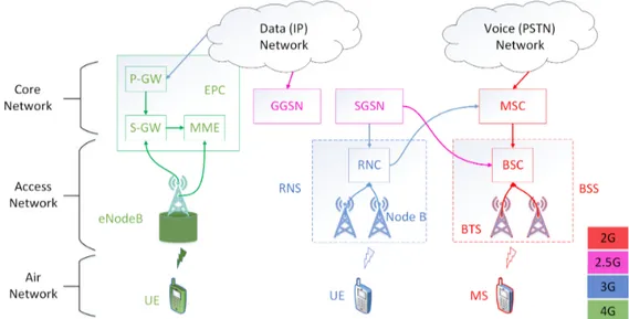
Figure 1.1 shows a comparison between the Network Architectures of 2G, 3G and 4G technolo-gies, demonstrating how the architecture of each architecture is structured with its evolution and how the successors of each one take advantage of its predecessor technologies to adapter evolution.
Figure 1.1: 2G, 3G and 4G network architecture, adapted from [1].
1.2.6
Fifth Generation
The Fifth Generation (5G) refers to Fifth Generation which was started from late 2010s. 5G Facilities that might be seen with 5G technology includes far better levels of connectivity and coverage. The main focus of 5G will be on world-Wireless World Wide Web (Wireless-WWW). It is a complete wireless communication with no limitations. The main features of 5G are:
• It is highly supportable to Wireless World Wide Web (Wireless-WWW); • High speed, high capacity;
• Provides large broadcasting of data in Gbps; • Multi-media newspapers;
• Faster data transmission that of the previous generation;
• Support interactive multimedia, voice, streaming video, Internet and other; • More effective and attractive.
Figure 1.2: 5G network architecture, adapted from [2].
Figure 1.2 shows the 5G network architecture. As 5G network uses flat IP concept so that different Radio Access Networks (RANs) can use the same single Nanocore for communication. The RANs supported by 5G architecture are GSM, GPRS/EDGE, UMTS, LTE, LTE-Advanced, WiMAX, WiFi, EV-DO and CDMA One.
Flat IP architecture identifies devices using symbolic names unlike hierarchical architecture where in normal IP addresses are used. This architecture reduces number of network elements in data path and hence reduces cost to greater extent. It also minimizes latency [2]. 5G aggregator aggregates all the RAN traffics and route it to gateway. 5G aggregator is located at Base Station Controller (BSC) Radio Network Controller (RNC) place. 5G mobile terminal houses different radio interfaces for each RAT in order to provide support for all the spectrum access and wireless technologies. Another component in the 5G network architecture is 5G nanocore. It consists of nanotechnology, cloud computing. Cloud computing utilizes internet as well as central remote
servers to maintain data and applications of the users. It allows consumers to use applications without any installation and access their files from any computer across the globe with the use of Internet.
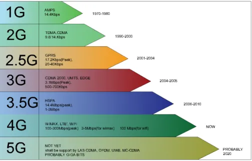
Figure 1.3 shown below the evolutionary line of mobile communication networks, which shows the time of implementation and use and the technology that has evolved through the process from to the 5G.
Figure 1.3: Evolution of mobile communication networks, adapted from [3]
1.3
Objectives and Approach
With the uncontrolled increase of the wireless communication devices, it has been an increasing challenge to meet the demand, aiming at this need for greater bandwidth and greater energy efficiency of the transmission and reception systems, being studied the use of technology that join elements of MIMO, such as continuous-aperture antennas and phased arrays, in order to reach Line of Sight (LoS). Includes at the most effective mathematical modulation for the Con-tinuous Aperture Phased Multiple Input Multiple Output (CAP-MIMO) proposal using a Discrete High-resolution Matrix Array (DLA) that communicates with analogue beamforming [20], [21], [22]. Multiple Input and Multiple Output (MIMO) technology is the use of multiple antennas at both transmitter and receiver to improve communication performance. The MIMO technology has attracted attention in wireless communications, because it offers significant increases in data throughput and link range without additional bandwidth or transmit power. It achieves this by higher spectral efficiency (more bits per second per hertz of bandwidth) and link relia-bility or diversity (reduced fading).
The approach comprises to compare different synchronization algorithms at the receiver and experimentally verify them with Universal Software Radio Peripheral (USRPs) and Adalm Pluto, implement a simple version of a receiver with 2x2 MIMO and synchronization, and make efforts to implement the receiver with a more complex structure towards massive MIMO.
1.4
Contributions
The main contribution of this dissertation was the elaboration of the Matlab project that origi-nated the following article and paper and some work was done in cooperation with the Univer-sidad Carlos III de Madrid, and some papers in conferences.
The work associated with this dissertation is based on research on the practical implementa-tion of MIMO and Massive MIMO that is being carried out in Instituto de Telecomunicações, in a collaboration with Universidad Carlos III de Madrid, and considers the research infrastructure of strategic relevance ORCIP (http://www.orcip.pt). With the inspiration of achieving future Beyond 5G networks operating in the millimetre wavebands enabled by joint Analogue-digital signal processing, we consider hardware architectures with USRPs and Adalm Pluto SDRs to ver-ify the feasibility of synchronization algorithms and simple MIMO configurations that will scale up while enabling to achieve more complex MIMO configurations, e.g., towards CAP-MIMO. An-other contribution is the Prototyping of an architecture of LTE-Advanced with different eNBs and Evolved Packet Core, with Open Air Interface.
This applied research in the work developed has already been reflected in the framework of the ORCIP project, and in a temporary document presented in COST CA 15104 the Inclusive Radio Communications (IRACON) and two posters, as follows:
• Development of the Temporary Document (TD(18)07019) to present the results of the test of Implementation of Low-complexity Hybrid Analogue-digital Solutions in CAP-MIMO, fo-cusing on SISO systems, presented at the Cartagena Meeting of COST CA15104 IRACON, of 30/5-1/6/2018 [23].
• Poster presentation on the ”‘Implementation of Low-complexity Hybrid Analogue-digital Solutions in CAP-MIMO”’, focusing on SISO systems presented at the 25th Thematic
Sem-inar on Mobile Communications (RTCM) held at the Faculty of Computer Science at the University of Porto, 06/22/2018.
• Poster on the ”‘Implementation of Low-complexity Hybrid Analogue-digital Solutions in CAP-MIMO”’, focusing on SISO systems, presented at Instituto de Telecomunicações, Insti-tuto de Superior Tecnico the University of Lisbon, 22/07/2018.
1.5
Outline of the Dissertation
Apart from this Chapter, this dissertation is divided into four chapters, which are briefly de-scribed below.
Chapter 2 discusses the new technology to meet the growing demand for demand related to the transmission frequencies, and the study of these technologies related to wireless systems with Multiple Antennas, concepts of Single Input Single Output (SISO), Single Input Multiple Output (SIMO), Multiple Input Single Output (MISO) and Multiple Input Multiple Output (MIMO) transmission capabilities.
The use of a more focused scheme in the investigation of Massive MIMO systems and the approach and conceptualization of the importance of the use of millimetre waves (mmWave) to supply the demand and lack of licensed bands and their generalization for transmitters and receivers is presented in chapter 3.
In chapter 4 present the implementation of the mathematical modulation implemented in Matlab while applying to the universal software radio peripherals (USRP) Hardware interconnected so that it forms a network in SISO standard, with capacity of application in 2x2 MIMO systems where the results obtained on the adopted implementation are analyzed.
Finally, chapter 5 summarizes the main ideas and conclusions of the developed work, as well as the contributions made and possible future work.
Chapter 2
Wireless Systems with Multiple Antennas
2.1
Introduction
The use of today’s wireless communication systems has been a bit undermined by the wide range of information being exchanged and are increasingly calling for high transfer rates, thus requiring more and more system improvements, and one of the most auspicious technology and the use of multiple antennas, which we will see in more detail below.
It is fundamental to understand the nature of the MIMO channel in order to operate the MIMO systems, as well as all its aspects. Wireless communication systems have been developed to transmit information through a radio channel between the transmitter and the receiver. In SISO systems the radio channel is formed by a single path between transmitter and receiver, ignoring the effects of multi-path fading. However in MIMO systems composed of several antennas for transmission and reception, the number of paths between transmitter and receiver is equal to the product between the number of transmitting antennas by the number of receiving antennas, as shown in Figure 2.1.
Figure 2.1: Multiple Input Multiple Output
2.2
Introduction Multiple Input Multiple Output
Multiple Input Multiple Output (MIMO) technology has been a major advance for 4G telecom-munication systems and a key driver for technology in 5G systems and other innovative next technologies.
MIMO technology has emerged as one of the most efficient in the middle of portability, where the transmission and reception of the signals must be carried out with considerable precision in order to avoid losses in signal quality. Bandwidth has become an extremely scarce resource,
and its use is becoming more and more expensive due to the large number of requests and the low demand.
The multi-system are used to allow many mobile users to simultaneously share a common band-width. Since traditional wireless communication is based on the use of antennas in the config-uration of a transmitter and receiver, or simply Single Input Single Output(SISO), as shown in Figure 2.2. The Base Stations (BS) are equipped with a different system, Single Input Multiple Output (SIMO) as shown in Figure 2.3 and Multiple Input Single Output (MISO) as shown in Figure 2.4, which can already have a significant gain. Different types of multiple access formats are being used, being one of the most used and most feasible and the effective gain in relation to the transfer and reception of data is the Multiple Input Multiple Output (MIMO) as shown in Figure 2.5.
Figure 2.2: Single Input Single Output.
Figure 2.3: Single Input Multiple Output.
Figure 2.4: Multiple Input Single Output.
2.3
Single Input Single Output
The simplest form of radio link can be defined as SISO, that is, single input and single output. This is effectively a standard radio channel, to which both a transmitter or a receiver operates with a single antenna. There is no diversity and no further processing is required.
of the various forms of diversity to which they are subjected. However, the SISO channel is limited in performance because the transmitted and received signal uses only a single path. Taking as interfering and fading the impact on the system more than a MIMO system using some form of diversity where the channel bandwidth is limited by Shannon’s law and the transfer rate be dependent on the channel bandwidth and signal relation/noise ratio [24].
2.4
Single Input Multiple Output
SIMO signal processing or single Input Multiple Output occurs where the transmitter has a single antenna and the receiver has multiple antennas. It is also known as a diversity receptor. They are often used to allow a system to receive signals from several independent sources in order to minimize the effects of fading. SIMO has been used in shortwave systems as listening / receiving stations to combat the effects of ionospheric fading and interference on incoming signals. SIMO has the advantage that the system is not as complex to be implemented, although it has some drawbacks in that processing is required at the receiver.
The use of SIMO may be quite acceptable in various applications, but to which the receiver is located in a mobile device, such as cellular telephone apparatus, where processing levels are limited by size, cost and battery consumption [24].
The SIMO can be used in two ways:
• Switching diversity SIMO: This form of SIMO searches for the strongest signal and switches to the antenna.
• Maximum ratio combining SIMO: This form of SIMO takes both signals and adds them to a combination. In this way, the signals from both antennas contribute to the overall signal
2.5
Multiple Input Single Output
The MISO system is an antenna technology for wireless communications, where multiple anten-nas are used to transmit signal, where antenanten-nas are combined to minimize errors and optimize the data transfer rate. The receiver has only one antenna that it uses to choose which signal to receive. In conventional wireless communications, a single antenna is used in the transfer, and another single antenna is used in the receiver. In some cases, this gives rise to problems with multiple path effects. When a signal is obstructed by an obstacle such as mountains, gorges, buildings. The late arrival of scattered parts of the signal causes problems such as fading, crop-ping and intermittent reception. In digital communication systems, such as wireless Internet,
can cause a reduction in data speed and an increase in the number of errors. The use of two or more antennas, together with the transmission of multiple signals in the transmission, can reduce the problem caused by the propagation of waves of several paths [24].
2.6
Multiple Input Multiple Output
Multiple Input and Multiple Output or simply MIMO, and the denotation of the use of several an-tennas in the transmission and reception of signals from a Base Station to another Base Station, using a set of antennas enables the transmission from several signals to a base station, which upon receipt of these signals, even if the signals arrive distorted, as the receiving antennas received several signals, these signals are combining generating a stable signal. In principle, MIMO offers three different benefits, namely spatial diversity, beamforming gain, and spatial multiplexing [25]. A MIMO system consists of several antenna elements at both transmitter and receiver, plus adaptive signal processing, this combination exploits the spatial dimension of the radio propagation channel [25]. MIMO technology opens enormous possibilities in the race for 5G improvement. Multiple Input Multiple Output is a method used to multiply the transmission capacity of multiple transmissions to antennas to exploit multiple propagation paths. The MIMO has become an essential element of wireless communication standards. MIMO applied in mil-limetre waves, with array of several antennas, and very interesting, since it provides a greater bandwidth and a wide range of free spectra, more due to the high number of antennas and the numbers of Radiofrequency (RF) chains that are required for the use of mmWave and MIMO, are quite high, considerably increasing the cost and affecting the energy efficiency, considering the use of beamspace in an attempt to reduce the complexity of the hardware [26].
MIMO emerges as a technology that uses the multiple antenna variant in both the transmitter and the receiver in order to obtain a diversity of paths by which the data signals are to be transported, due to the diversity of paths that the data can travel separately for each antenna both in the transmission and in the reception of the signal, denominated as multiple inputs and multiple outputs, thus improving the data to be communicated. In order to solve future problems with the large amount of data required by the large number of data-dependent equipment to be sent or received, MIMO technology provides a higher transfer rate, together with greater coverage distances, providing greater capacity of users and more reliability in the signal, that when using the variant of multiple antennas provides an effective gain in Transmission and Reception without it is necessary to increase the bandwidth nor the power of transmission. Shown in Figure 2.5, the MIMO system intends the total study of the spatial domain. Thus, MIMO generates an expressive gain in diversity, beam acquisition, and the ability to transmit and
receive shared data. In the context of the diversity of the characterization of the environment that can be applied MIMO, and the possibility of using multiple antennas in the information sharing by the use of multipath that become independent, since each antenna that is used in the MIMO set sends or receives a part of the information or receive various different information. One of the main challenges related to the use of the MIMO system and the significant gain in the transfer rate that is provided by the multiplexing of the antennas leading to a high reliability of the information transferred and received.
Figure 2.5: Multiple Input Multiple Output.
2.7
MIMO Transmission Techniques
MIMO consists of a communication system that uses two or more antennas at the transmission end and two or more antennas at the receiving end. This fact implies that, using spatial diver-sity techniques, spatial multiplexing, beamforming techniques that, through the use of several antennas in transmission and reception, allow an expressive gain in transmission capacity. How-ever, current systems do not use all the benefits that these techniques can provide, simply by using systems with few antennas, will be discussed in more detail these technologies in the course of this chapter.
2.7.1
Diversity
Diversity can be defined as the technique that is used to overcome wear on the quality of the signal transmitted and received due to external media interference that are subject to exposure in various environments. The attenuation effect can be reduced by transmitting the same signal in different channels, i.e. by creating replicas of the original signal transmitted to the receiver, and thereby receiving the receiver several data simultaneously, thereby reducing the possibility of the received signal being damaged, thus increasing signal quality and transmission reliability [27]. The main system that suffers from the signal transmission and reception process are the mobile devices, and this has been the constant use of diversity techniques, in order to reduce the effects of the attenuation of multiple paths. Diversity systems can be represented by the
number of channels used. They can be divided into three systems, time diversity, frequency diversity and space diversity.
2.7.1.1 Time Diversity
Time diversity can be achieved by interleaving and encoding symbols at different coherent time periods. In this type of technique, we calculate the mean of channel fading over time using channel coding and interleaving to allow each replicate of transmitted signal is affected by different fading over time in order to minimize any deep fading, and thereby avoiding a more significant loss during data transmission. The diversity of time has a consequence that can not be exposed, which is the additional delay in the transfer of data, thus generating a loss in efficiency [27]. Figure 2.6 shows the interleaving principle in time. The replicates of the transmitted data are interlaced, so that multiple transmission is possible for a longer period of time.
• Repeatedly transmits information at the time spacing that exceeds the coherence time of the channel;
• The interval between transmission of same symbol should be at least the coherence time (∆t)c;
• Different copies undergo independent fading;
• Reduction in efficiency (effective data rate<real data rate).
Figure 2.6: Time diversity, adapted from [4].
2.7.1.2 Frequency Diversity
Frequency diversity is implemented by transmitting the same data at different frequencies of the emitter. Thus making the emitter frequencies uncorrelated with the other frequencies,
so that they are not affected by the same fades. In order to make them less correlated, the sending frequencies are sent by more than the bandwidth which have the same coherence of the channel.
• Is implemented by transmitting same information on more than one carrier frequency; • The separation between the carriers should be at least the coherent bandwidth (∆f )c; • Different copies undergo independent fading;
• Only one antenna is needed.
Figure 2.7: Frequency diversity, adapted from [4].
2.7.1.3 Spatial Diversity
Spatial diversity refers to a method for improving the reliability of a data signal by using various communication channels of transmitting and receiving characteristics, spatial diversity tech-niques predominantly aim at improved error performance and can be applied based on a diver-sity gain and coding gain. They can also be used to improve bit rates when used in conjunction with an adaptive modulation/channel coding scheme [12].
Diversity plays an important role in combating fading and between-channel Interference and avoiding error bursts [28].The spatial diversity in the transmission and reception uses two sepa-rate antennas and are placed in disposition to act with the function of transmitting and receiving
data. This configuration mode eliminates the need for a duplexes that is used to be able to trans-mit and receive signal from a single antenna, with the configuration of spatial diversity we can use the variation of multiple antennas. Different types of combination techniques are used in spatial diversity as can be seen in Figure 2.8. Spatial diversity can be achieved with the aid of multiple transmitting antennas in transmission diversity or multiple receive antennas reception diversity with sufficient spacing between the antennas [29].
Figure 2.8: Space time diversity, adapted from [4].
Figure 2.9: Space frequency diversity, adapted from [4].
low such that the gain in amplitude and phase change in the propagated signal is imperceptible, thereby increasing the difficulty of the signal undergoing a strong attenuation. In SISO diversity can be obtained in the time or frequency domain, that is, the diversity of the signal can be applied at different times or at different frequencies, thus consuming a lot of bandwidth making the system technically limited. Spatial diversity can be divided into two segments, diversity of reception and diversity of transmission. In diversity of reception a multiple antenna architecture is used in the receiver, where each antenna is responsible for receiving a copy of the transmitted signal, where the multiple copies are then combined in order to maximize the received signal and minimize the amount of SINR - there by improving the quality of the received signal.
2.7.1.4 Space Time Transmission Diversity
In the Space Time Transmission Diversity (STTD) schemes, the signals are sent by different anten-nas in order to pass through different channels, in this way, the possibility of receiving a signal that has undergone a less degradation appears. This allows the transmitted data to contain the same information. The main use of the space-time diversity, and the increase of the reliability of the data, thus allowing to obtain greater robustness of data using this type of technique. The shown in Figure 2.10 exemplifies the basic spatial of the processing in the transmission by diversity of space-time.
Figure 2.10: Space time block code with diversity space, adapted from [5]
Space Time block coding is a technique used in wireless communications to transmit multiple copies of a data stream across a number of antennas to improve the reliability of data received and transmitted. As the transmitted signal must travel in a potentially difficult environment with scattering, reflection, refraction, so the signal can be corrupted by the noise at the receiver, ie the coding space time combines all copies of the received signal in such a way as to be extracted the maximum information of each signal.
2.7.1.5 Spatial multiplexing
Spatial multiplexing techniques aim to provide higher bit rates taking into account a single antenna system, but spatial diversity techniques aim to achieve improved error performance. It is performed based on a diversity gain and a coding gain in the systems to be considered. Indirectly, spatial diversity techniques can also be used to improve bit rates when applied in conjunction with a modulation coding scheme in relation to the adaptive channel [7].
The signal transmitted and divided into several separate smaller and independent beam se-quences on different channels, thus occupying a much smaller bandwidth than would be re-quired if it were sent by a single channel [30].The data are transmitted by the beams to the receivers through the antennas, and there may be several antennas coupled together. The data is sent on the same frequency of the carrier, to which it will be received by the receivers, the receiver will be responsible for regrouping the signals in a single signal [31].
The spatial multiplexing is one of the MIMO systems to which the ability of this type of sys-tems to explore the capacity of each channel is related, thus managing to increase the data transmission rate of the system without the necessity of increasing any bandwidth or power of streaming. By means of the spatial multiplexing technique it is possible to obtain a linear increase in the capacity of a MIMO system by the number of antenna pair existing between the transmission/reception ratio or min (MT × NR) [32], which are used virtual channels parallel,
orthogonal to each other, by which the information to be transmitted is multiplexed. Consid-ering that a MIMO system consists of several SISO channels, so the MIMO system will present a capacity gain many times higher than the SISO system. Having the disadvantage of using spatial multiplexing is the increase in complexity in the transmitter, and consequently in the receiver. Due to the increase in complexity, it appears in most decoding algorithms that the number of antennas in the receiving zone must be at least equal to the number of transmit antennas [32]. Another disadvantage presented by the technique of spatial multiplexing is the possibility that only a diversity of NR is obtained, and not a total diversity of (NT × NR), thus generating an
increase in the probability of error.
The increase in the capacity of a MIMO system is then the result of applying the spatial multi-plexing technique, which divides the information to be transmitted by parallel virtual channels.
A = [
S1 S2 S3 S4 S5 S6
] (2.1)
A = S1 S4 S2 S5 S3 S6 (2.2)
The basis of multiplexing is to divide, as such, into spatial multiplexing, the data streams are divided into layers or branches and transmitted separately through each space or each indepen-dent antenna, being transmitted at the same frequency, in matrix 1 we can iindepen-dentify a system SISO where we have the data being transmitted by a single channel, already in the matrix 2 applying the multiplexing, it can be seen that the data are divided and transmitted by two channels or branches, the amount division will be limited the amount of transmitting antennas. As shown in Figure 2.11.
Figure 2.11: Spatial multiplexing channel matrix adapted from [6]
2.8
Channel Capacity in MIMO
Wireless communication systems are limited by the capacity of channels available and the bur-den on licensed spectrum, coupled with the exorbitant cost of such spectrum. According to theorem Shannon’s [7] the Additive White Gaussian Noise (AWGN) channel is limited by the data transfer rate, which can approach theoretically the maximum transmission rate on a channel bandwidth by equation (2.3). Based on the assumption that the channel is a white Gaussian noise and the interference effects are not considered explicitly.
Increasing the bandwidth capacity of the channel used for transmission is not always a viable solution, given the amount paid by the spectra. In addition, the power used for data trans-mission as well and limited, especially where the battery and the power supply, leading to a context that for greater amount of power and need to increase the amount of energy in the power supply, or increase the size of the batteries. As an example of multiple antenna systems at the receiver and transmitter ends as shown in Figure 2.12, each antenna exhibits multiple input and multiple output channels where the capacity of each channel can be estimated by the capacity formula based on the theorem Shannon’s, as can be seen from the equation (2.3).
In practice, a SISO system is considered where equation (2.3) provides a maximum limit for the transmission rate in the SISO system in order to obtain an error-free system:
CSISO= B· log2(1 +
P NoB
) (2.3)
where:
• C - is the transmission capacity of the channel; • B - is the bandwidth on a channel;
• P - is the transmitted signal power; • N o - it is the single-sided noise spectrum.
If the baud rate is less than C bps, you must follow an appropriate encoding scheme that can lead to reliable and error-free transmission. If the baud rate is greater than C bps, then the received signal, regardless of the data size, will involve bit errors.
Figure 2.12: MIMO Channel, adapted from [7].
We consider an antenna array with ntelements at the transmitter and an antenna array with
nr elements at the receiver. The impulse response of the channel between the jthtransmitter
element and the ithreceiver element is denoted as h
i,j(γ, t). The MIMO channel can then be
described by the nr× nt, H(τ, t) in matrix notation as shown below:
H(τ, t) = h1,1(τ, t) h1,2(τ, t) · · · h1,nt(τ, t) h2,1(τ, t) h1,2(τ, t) · · · h1,nt(τ, t) .. . ... · · · ... hnr,11(τ, t) hnr,2(τ, t) · · · hnr,nt(τ, t) (2.4)
The matrix elements are complex numbers that correspond to the attenuation and phase shift that the wireless channel which was introduced to the signal reaching the receiver with delay
τ. As can be seen in Figure (2.5). Where it can be expressed by the following equation for MIMO system::
y(t) = H(τ, t)⊗ s(t) + u(t) (2.5)
Where ⊗ denotes convolution,s(t) is a nT x x 1 vector corresponding to the nT x transmitted
signals, y(t) is a nRxx1 vector corresponding to then nRxreceived signals and u(t) is the additive
white noise.
If we assume that the bandwidth of the transmitted signal is close enough that the channel response can be treated as a flat signal through the frequency, then the discrete time description may correspond to (2.6) is as follows:
rτ = Hsτ+ uτ (2.6)
Considering a MIMO channel with nRx receiving antennas and nT x antennas transmitters, the
H-channel transfer matrix has dimension nRx× nT x. O element ij of matrix H corresponds
to the result of propagation of the signal from the jn transmitting antenna to the in receiving
antenna. Thus, which can be calculated by (2.7):
⃗
r = H⃗s + ⃗n (2.7)
where ⃗r is the vector column of dimension nRx× 1 which corresponds to the signal received on
each of the receiving antennas nRx,⃗s is the vector column of dimension nT x×1 which corresponds
to the signal transmitted by each of the transmitting antennas nT xand n corresponds to the noise
column vector of dimension nT x× 1. One can determine each of the elements of the matrix H
through the parameters of the multipath components, can be obtained from equation (2.8):
Hik= ns ∑ p=1 [ γpej( 2π λid sin(φRx,p))ej(2πλkd sin(φT x,p)) ] (2.8)
wave-length, d is the spacing between the antennas of the transmitter and receiver sets; the angle of arrival at the receiver being relative to the normal to the receiver set and φT ,p being the
starting angle of the transmitter relative to the transmitter assembly. The capacity of a com-munications channel can be deduced by Shannon’s theorem as described [33], corresponding to the maximum error-free transmission rate supported by the channel to be used. Taking this con-sideration, the standard formula deduced by Shannon’s for the capacity, expressed in bit/s/Hz, as it can be observed from equation (2.9):
CM IM O = log2(1 +
S
N|H|2) (2.9)
The challenge of increasing transmission rates and the reliability of information involves a num-ber of difficulties. According to Shannon’s theorem to increase the capacity of a channel in (bps) it is necessary to increase the transmission bandwidth or increase the signal-noise Ratio (SNR). The limitation to the use of higher bandwidth is in the fact that the frequency spectrum is a rare and expensive resource. On the other hand, in order to increase the SNR it is necessary to increase the transmit power, which is not desirable, since in a mobile device that must coexist with the need for frequency reuse and also with the longevity of the battery life, as well limiting the amount of power that can be implemented. A MIMO system with NT transmitting antennas
and NRreceiving antennas has a capacity given by [5], as can be expressed in equation (2.10):
CM IM O = log2det(IN r+
Pt
N.Nt
H.Q.H+) (2.10)
Where:
• CM IM O - is the transmission capacity of the channel;
• IN r - is the dimension identity matrix NR× NT;
• H - is the dimension Channel matrix NR× NT;
• N o - it is the single-sided noise spectrum;
• H+ - is the trasn-conjugate matrix of the channel N
R× NT;
• Q - is the covariance matrix of the signal vector to transmit.
For systems with Transmitter without MIMO Channel Information. In the case where the transmit-ter has no information about the transmission channel, each transmitting antenna is considered
to radiate the same power and the transmitted signals are independent. This consideration leads to Q = IN t. Substituting the matrix Q into equation (2.10) and effecting the self-decomposition
of HH+, denoted by λ
k, according to [5], one obt the capacity of the MIMO channel under these
conditions we can verify how it can be expressed in the equation (2.11):
CM IM O= log2det(IN r+
Pt
N.Nt
λk) (2.11)
We notice that the achieved capacity depends on the algorithm used for allocating power to each sub-channel. The theoretical analysis assumes the channel state known at the receiver. This assumption stands correct since the receiver usually performs tracking methods in order to obtain CSI, however the same consideration does not apply to the transmitter [7]. When the channel is not known at the transmitter, the transmitting signal s is chosen to be statistically non-preferential, which implies that the nT xcomponents of the transmitted signal are
indepen-dent and equi-powered at the transmit antennas.
From equation (2.11), it is seen that the capacity of the MIMO channel is the sum of the inde-pendent SISO channels capacities NR, where the SISO channel gains are the eigenvalues of the
matrix HH+ and whose total power is evenly distributed for each transmitter antenna. In this
case the MIMO system allows an increase of the capacity that grows linearly with min (NT, NR).
Since the gain of capacity depends on the eigenvalues of the matrix HH+, if the gains have
low or zero values it may be impossible to perform the transmission in a virtual channel, so that power of the channel signal may not be sufficient to reach the receiver.
Where S/N corresponds to the signal-to-noise ratio and H, the transfer matrix of the channel. Observing the equation (2.11), it is verified that a growth of 3 dB in the relation Signal-to-noise ratio, causes a 1 bps/Hz increase in capacity. In the case of MIMO systems, the calculation of capacity is related to the diversity of space in which the receiver makes the most of the data received by vector ⃗r. Assuming that the vector ⃗s of the transmitted signal is composed of equal and statistically independent nT xcomponents, each with a Gaussian distribution, we can
deduce the capacity for a MIMO system from equation (2.11).
2.8.1
Capacity of Orthogonal Channels
Capacity of the Orthogonal Channel, has as finality to study the capacity of the channel MIMO where the system has its capacity maximized. As an example we consider a simple case where we will have a composite MIMO system can nt= nr= n, along with a fixed total power through
the SISO sub-channels, i.e∑k=1ε2
is concave in the variables ε2
k (k= 1,2, ..., n), and as a result, maximizing your system when
ε2k = ε2i = a/n( k= 1, 2, ..., n). Thus, the equation can show that HH+ = H+ = (a/n)I
n.
Substituting HH+= (a/n)I
n into the equation (2.12).
CM IM O= log2[det(I +
pa
n2In)]⇒ C = n.log2(1 +
pa
n2) (2.12)
If|Hi,j|2= 1, the matrix H satisfies HH+= nIn, hence, equation (2.13) became,
CM IM O= log2[det(I +
p
nnIn)]⇒ C = n.log2(1 + pa) (2.13)
The last equation indicates that the capacity of an orthogonal MIMO channel is n times the capacity of the SISO Channel.
2.8.2
Simulation Capability MIMO Channel
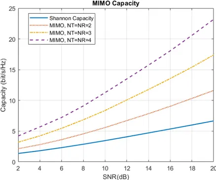
The MIMO channel simulation capability, using the Matlab simulation platform, makes it possible to compare the Shannon capacity and the MIMO channel capacity for different MIMO systems. In Figure 2.13 we have shown the simulation results of mean MIMO channel capacity for different distributions. Shannon capacity for Gaussian channel, is compared with other distributions. Channel is assumed with perfect estimation at both transmitter and receiver. The capacity of a MIMO channel with nttransmit antenna and nr receive antenna is analyzed. MIMO capacity
dependencies (bit/s/Hz), and SNR (dB), in this simulation we used the initial simulation results SNR = 2, for MIMO 2x2, MIMO 3x3, MIMO 4x4 systems capacity. In Figure 2.13 it can be observed that with the increase of the number of antennas we have a greater variation of the SNR in relation to the number of antennas, where the transmission capacity in (bit/s/Hz) of each system is increased when a larger number of antennas are introduced, so it is possible to use multiple antenna systems for more reliable transmission. We can also verify that, from the results shown in Figure 2.13, it is possible to visualize that the capacity of the MIMO channel increases as we increase the number of antennas.
2.9
Capacity of SIMO and MISO Channel
Single Input Multiple Output (SIMO) and Multiple Input Single Output (MISO) channels are special cases of MIMO channels. In this paragraph discuss the capacity formulas for the case of SIMO
Figure 2.13: MIMO Capacity, according to equations (2.3) and (2.13)
and MISO channels. For a SIMO channel ntx=1, so n = min(nrx,ntx)=1, hence, this channel state
information (CSI) at the transmitter does not affect the SIMO channel capacity [7]:
CSIM O= log2(1 +p× ε21) (2.14)
If we considered|hi|2= 1then ε21= nrx. Hence equation (2.15) stands:
CSIM O= log2(1 +p× nr) (2.15)
MISO systems are systems that have multiple antennas in the transmitter and only one antenna in the receiver. Using the channel capacity for CSI in the receiver with fast fading, we can find channel capacity for MISO systems by analyzing the behavior of the equation (2.16) [7].For a Multiple Input Single Output (MISO) channel nr = 1and n = min(nr, nt) = 1. With no channel
state information (CSI) at the transmitter, the capacity formula can be expressed as follows:
CM ISO= log2(1 + (
p nt
)× ε21) (2.16)
![Figure 1.2: 5G network architecture, adapted from [2].](https://thumb-eu.123doks.com/thumbv2/123dok_br/18859921.930284/30.892.138.709.394.744/figure-g-network-architecture-adapted-from.webp)
![Figure 2.7: Frequency diversity, adapted from [4].](https://thumb-eu.123doks.com/thumbv2/123dok_br/18859921.930284/41.892.276.658.380.801/figure-frequency-diversity-adapted-from.webp)
![Figure 2.9: Space frequency diversity, adapted from [4].](https://thumb-eu.123doks.com/thumbv2/123dok_br/18859921.930284/42.892.171.680.670.1075/figure-space-frequency-diversity-adapted-from.webp)
![Figure 2.10: Space time block code with diversity space, adapted from [5]](https://thumb-eu.123doks.com/thumbv2/123dok_br/18859921.930284/43.892.217.721.720.915/figure-space-time-block-code-diversity-space-adapted.webp)
![Table 3.1: Global spectrum bandwidth allocation, adapted from [12] Band Uplink (MHz) Downlink(MHz) Carrier Bandwidth (MHz) 700 MHz 746-763 776-793 1.25-10 AWS 1710-1755 2110-2155 2-15 IMT Extension 2500-2570 2620-2690 2-20 GSM 900 880-915 925-960 1.25-5 UM](https://thumb-eu.123doks.com/thumbv2/123dok_br/18859921.930284/60.892.255.591.138.361/global-spectrum-bandwidth-allocation-downlink-carrier-bandwidth-extension.webp)
![Figure 3.3: Transmission protocol of TDD Massive MIMO, adapted from [9]](https://thumb-eu.123doks.com/thumbv2/123dok_br/18859921.930284/68.892.182.684.117.501/figure-transmission-protocol-tdd-massive-mimo-adapted.webp)