Brazilian Microwave and Optoelectronics Society-SBMO received 1 Oct 2018; for review 9 Nov 2018; accepted 16 Nov 2018 Brazilian Society of Electromagnetism-SBMag © 2018 SBMO/SBMag ISSN 2179-1074
Abstract—This work reports a dual-band radar system composed of aphotonics-based transceiver and a unique dual-band antenna. The proposed antenna consists of an integration of conventional focal-point and Cassegrain parabolic antennas in the same structure, ensured by using a subreflector based on a frequency selective surface. Numerical and experimental results in terms of the antenna reflection coefficient, radiation pattern and gain are reported with excellent agreement over both frequency ranges. The innovative dual-band photonics-based radar transceiver operates simultaneously in the S- and X-bands. The radar system has been properlyvalidated by multiple detections of helicopters and airplanes in real conditions.
Index Terms—Antennas, dual-use radars, frequency selective surface and radar. I. INTRODUCTION
Currently, most transceivers operate only in a single band. New architectures have been proposed to simultaneously operate in multiple bands, by using independent hardware for each band [1], [2]. Future generations of radar systems aim to meet reconfigurability, multi-functionality and small footprint characteristics in order to provide improved sensors networks [3]. In this context, in the past few years, researchers have proposed photonics-based radar technologies to achieve coherent multiband and multi-functionality capability, by applying software-defined radio (SDR) [4]-[6]. In this way, multiple radiofrequency carriers are combined for enabling short- and far-range detections. Since higher frequencies are more vulnerable to the weather conditions, they are usually used for short-range applications, whereas lower frequencies are desirable for far-range detections [7]-[9]. Therefore, a multiband radar transceiver increases the system robustness in terms of climatic variations, providing enhanced detection capability even in adverse conditions. Finally, combining multiple functions in a unique hardware allows a general size, weight and energy consumption reduction.
Several approaches for designing dual-band antennas are found in the literature [10]-[13]. For instance, M. Pachiyaannan et al. have reported dual-band printed antennas for UWB radar applications. Particularly, our research group has been focused on developing multiband
waveguide-Dual-band System composed by a
Photonics-based Radar and a Focal-Point/Cassegrain
Parabolic Antenna
T. H. Brandão1, H.R.D. Filgueiras1,2, A. A. C. Alves1,2, F. Scotti3, S. Melo3, A. Bogoni3, Arismar Cerqueira S. Jr.1
1Laboratory WOCA, National Institute of Telecommunications (Inatel), João de Camargo Avenue, 510, Santa Rita do Sapucaí, MG, Brazil, tiagob@get.inatel.br, arismar@inatel.br
Brazilian Microwave and Optoelectronics Society-SBMO received 1 Oct 2018; for review 9 Nov 2018; accepted 16 Nov 2018 Brazilian Society of Electromagnetism-SBMag © 2018 SBMO/SBMag ISSN 2179-1074 based antennas for radars [11]-[13] and communications [14], [15]. FSS-based subreflectors have also been applied for multi-band antennas [16]-[18]. In [16], an inductive FSS subreflector has been employed on a dichroic subreflector to electromagnetically separate the S- and K-band feeders for satellite communication applications. A flat dichroic FSS subreflector for Cassegrain antennas has been proposed in [17] for achieving high electromagnetic transparency between 1.9and2.3 GHz and high reflectivity between 3.6and4.2 GHz. Additionally, other authors have proposed a four-band response FSS which reflects in the Ka-band frequency range, whereas in S-, X-, and Ku-bands, it behaves as an electromagnetic transparent element [18].
The current manuscript represents an extension of two previous works from our research group [12], [13], which reported numerical and preliminary experimental results of a dual-band Cassegrain parabolic antenna based on frequency selective surfaces (FSS), designed to simultaneously operate at 2.525 and 9.925 GHz [19]. Here, we present the antenna full characterization and application in conjunction with a photonic-based radar transceiver, previously proposed by our group [5], for multiple radar detections of helicopters and airplanes in the S- and X-bands.
The manuscript is structured in five sections. Section II is regarding the FSS-based Focal-Point/Cassegrain parabolic antenna design. Its numerical and experimental results in terms of reflection coefficient, radiation pattern and gain are presented in Section III, whereasthe photonics-based radar experiment is described in Section IV. Finally, conclusions and future works are outlined in Section V.
II. FSS-BASED FOCAL-POINT/CASSEGRAIN PARABOLIC ANTENNA DESIGN
Frequency selective surfaces consist of conducting or aperture elements, arranged in a planar periodic array for creating a band-pass or band-stop filter [20]-[22]. The elements can be placed in one or more dielectric layers, according to the desired frequency response. The FSS properties can be varied by choosing the element type, dimensions and volumetric structure, as well as the dielectric material electromagnetic properties [21]. In dual-reflector systems, a FSS can be applied to the subreflectorin order to combine focal-point and Cassegrain parabolic antennas into a single structure [12], [13], [23].
The antenna design, including the dielectric support, horn antennas andFSS-based subreflector are depicted in Fig. 1(a). Fig. 1(b) describes the operational principle for the two frequency bands; the solid and dashed arrows indicate the wave electromagnetic (EM) path in the S- and X-bands, respectively. The horn antennas were based on two commercial waveguides, namely WR-340 for the S-band and WR-90 for the X-band. Their dimensions were calculated according to the design theory found in [24].
Brazilian Microwave and Optoelectronics Society-SBMO received 1 Oct 2018; for review 9 Nov 2018; accepted 16 Nov 2018 Brazilian Society of Electromagnetism-SBMag © 2018 SBMO/SBMag ISSN 2179-1074
𝐹 =𝑑4 cot 𝜃2 (1)
in which d is the main reflector diameter and θab is the horn antenna beamwidth. Using a
commercial main reflector with d = 1.5 m and considering θab= 56º for the horn antenna, the resulting
focal distance was F = 70.53 cm. A phase variation effect onto the paraboloid occurs when the feeder is placed near to the subreflector. We have defined the distance between the main reflector and X-band horn antenna as 2 cm in order to minimize such effect. With the previously calculated focal distance (F), it was possible to obtain the distance between the feeders, by subtracting 2 cm from F, which results in Zo= 68.53 cm.
(a)
(b)
Fig. 1. FSS-based Focal-Point/Cassegrain parabolic antenna: (a) Antenna main components, (b) Operational principle. The X-band feeder beamwidth was considered cd = 38º and (2), (3) and (4) were used to calculate
the FSS-based subreflector diameter (D), its eccentricity (e) and the distance between the S-band feeder and subreflector (L), respectively. The obtained dimensions were D = 28.64 cm, e = 5.22 and L = 27.7 cm.
𝐷 = 2 × 𝑍
( )+ ( )
(2)
𝑒 =sin
sin (3)
Brazilian Microwave and Optoelectronics Society-SBMO received 1 Oct 2018; for review 9 Nov 2018; accepted 16 Nov 2018 Brazilian Society of Electromagnetism-SBMag © 2018 SBMO/SBMag ISSN 2179-1074
The antenna operation has been numerically validated using ANSYS HFSS. We have performed a numerical sweep in the focal distance (F), FSS-based subreflector diameter (D) and spacing between the S-band feeder and subreflector (L), with the aim of enhancing gain at both frequencies. The final antenna dimensions were: F = 77.1 cm; L = 30.84 cm; D = 29.14 cm. The FSS-based subreflector design has been conducted aiming to obtain a band-reject filter [12]-[13], by considering the following parameters: dipole length (ld) and width (td); spacing between elements (delements); Arlon
Diclad 880 dielectric constant r = 2.2 and thickness h = 1.6 mm. The FSS cell has been designed considering the average relative permittivity ef = 1.60, since the EM wave travels in either air and
dielectric substrate. The variables ld and tdwere considered as one-half and one-eighth of the effective
wavelength (λef), which yield in 12.16 and 6.08 mm, respectively, at 9.925 GHz. The sub-reflector
prototype has been produced by connecting triangular, quadrangular and rectangular pieces of the dielectric substrate. We have performed numerical sweeps of the crossed dipole dimensions, since the subreflector is neither plane nor an infinity array, as considered in the Floquet method. The numerical sweep analysis has been conducted to guarantee high reflectivity response in the X-band for increasing the antenna gain. Fig. 2(a) shows the unit cell from the Floquet Method, whereas Fig. 2(b) displays the FSS-based subreflector details, including its final dimensions.
(a)
(b)
Fig.2. FSS-based subreflector: (a) Crossed-dipole cell: ld = 12.51 mm; td = 5 mm; delements = 18.9 mm, (b) FSS-based subreflector dimensions.
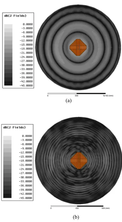
Brazilian Microwave and Optoelectronics Society-SBMO received 1 Oct 2018; for review 9 Nov 2018; accepted 16 Nov 2018 Brazilian Society of Electromagnetism-SBMag © 2018 SBMO/SBMag ISSN 2179-1074 (Fig. 3(a)) and 9.925 GHz (Fig 3(b)). In both cases, it is noted uniform energy distribution on the entire main reflector, which indicates that the FSS-based subreflectorwas well designed. This was concluded because the X-band electromagnetic wave only arrives at the paraboloid if reflected by the FSS-based subreflector.
(a)
(b)
Fig. 3. Current density distribution over the antenna main reflector: (a) S-Band, (b) X-Band.
III. ANTENNA PROTOTYPE CHARACTERIZATION
Brazilian Microwave and Optoelectronics Society-SBMO received 1 Oct 2018; for review 9 Nov 2018; accepted 16 Nov 2018 Brazilian Society of Electromagnetism-SBMag © 2018 SBMO/SBMag ISSN 2179-1074 which harms the antenna performance, mainly in terms of radiation pattern and gain. A vectorial network analyzer has been used to measure the antenna S-parameters. Figs. 5(a) and 5(b) present comparisons between the simulated and measured reflection coefficient for the S- and X-bands, respectively, which are in excellent agreement. The prototype bandwidths were 290 MHz (11.91%) at 2.435 GHz and 3.9 GHz (43.86%) at 8.89 GHz.
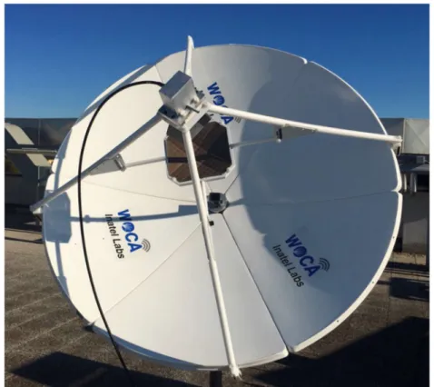
Fig.4. FSS-based Focal-Point/Cassegrain parabolic antenna prototype.
(a)
(b)
Fig. 5. FSS-based Focal-Point/Cassegrain parabolic antenna reflection coefficient. Measurement (solid blue line) and simulation (dashed red line) (a) in the S-band, (b) in the X-band.
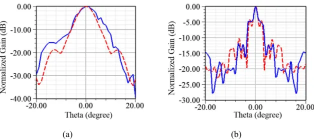
Brazilian Microwave and Optoelectronics Society-SBMO received 1 Oct 2018; for review 9 Nov 2018; accepted 16 Nov 2018 Brazilian Society of Electromagnetism-SBMag © 2018 SBMO/SBMag ISSN 2179-1074 24.5 dBi, respectively. The antenna gain at 9.925 GHz was expected to be approximately 12 dBi higher than that at 2.525 GHz, according to reflector antenna theory [24], since the main reflector is electrically large at higher frequencies. Such behavior has not been observed due to the FSS-based subreflector lower efficiency. The efficiency is decreased due to losses inserted by the dielectric and fabrication imprecisions, such as air gaps between the dielectric pieces. In other words, the Focal-Point Parabolic antenna and the Cassegrain Parabolic antenna present distinct radiation and aperture efficiencies due to the FSS-based subreflector presence in the latter one.
Fig. 6. Far-field radiation pattern characterization.
(a)
(b)
Fig. 7. FSS-based Focal-Point/Cassegrain parabolic antenna radiation pattern. Comparison between measured (solid blue line) and simulated (dashed red line) results (a) at 2.525 GHz, (b) at 9.925 GHz.
IV. DUAL-BAND PHOTONICS-BASED RADAR SYSTEM
Brazilian Microwave and Optoelectronics Society-SBMO received 1 Oct 2018; for review 9 Nov 2018; accepted 16 Nov 2018 Brazilian Society of Electromagnetism-SBMag © 2018 SBMO/SBMag ISSN 2179-1074 CNIT building, located close to the Pisa International Airport Galileo Galilei, with the purpose of detecting land and take-off of non-cooperative aerial targets. Fig. 8(b) depicts the full radar system block diagram. The waveform generator simultaneously generates two RF carriers at the intermediate frequencies 75 and 125 MHz. The block “RF photonics-based generator” is responsible for optically modulating the signals to enable an all-optical RF up-conversion. A photodetector executes the optical-electrical conversion at 2.525 and 9.925 GHz, with approximately 18 MHz bandwidth each. Both generated signals are simultaneously transmitted by the FSS-based Focal-Point/Cassegrain parabolic antenna for target detection. The signals echoes are received by the same antenna and modulated in the optical domain. The “RF photonics-based receiver” performs an all-optical RF down-conversion to the intermediate frequencies to be analyzed by digital signal processing.
(a)
(b)
Brazilian Microwave and Optoelectronics Society-SBMO received 1 Oct 2018; for review 9 Nov 2018; accepted 16 Nov 2018 Brazilian Society of Electromagnetism-SBMag © 2018 SBMO/SBMag ISSN 2179-1074
the radar system.
We have configured the radar with the same parameters at both RF frequencies, as follows: 50 Hz Doppler frequency (fd); frequency deviation chirp of 18 MHz; 10 kHz of pulse repetition frequency
(PRF). The distance resolution (R) is obtained by applying R = c/(2×B), where c is the vacuum speed of light and B is the RF bandwidth (B = 18 MHz), giving rise R = 8.33 meters. The speed resolution (vr) is determined by (5), in whichft is the RF carrier frequency, which results in 2.97 and 0.76 m/s for
the S- and X-bands, respectively. More details on the radar configuration can be found in [5] and [26].
𝑣 =𝑐 × 𝑓2 × 𝑓 (5)
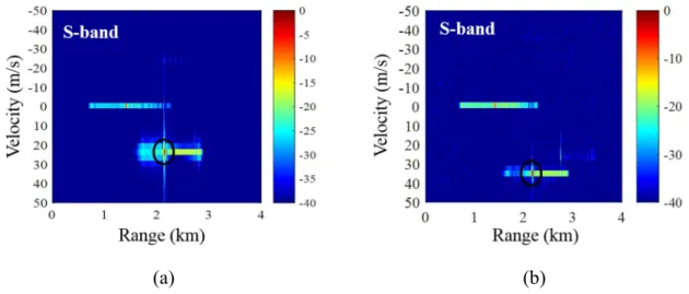
We have conducted the experiments in three steps: X-band detection; S-band detection; simultaneous detection using both bands. Fig. 9 presents an airplane detectionin the S-band, while it was taking off, with 25 m/s (Fig. 9(a)) and 35 m/s (Fig. 9(b)). We have detected the airplane at the same distance of 2.1 km, because its route circulates the building, as illustrated in Fig. 8(a). Fig. 10 reports the Doppler map detections of another airplane at 2.9 km distance and approximately the same velocity of the first target.
(a)
(b)
Brazilian Microwave and Optoelectronics Society-SBMO received 1 Oct 2018; for review 9 Nov 2018; accepted 16 Nov 2018 Brazilian Society of Electromagnetism-SBMag © 2018 SBMO/SBMag ISSN 2179-1074
(a)
(b)
Fig. 10. Airplane detections in the X-band: (a) Detection 1, (b) Detection 2.
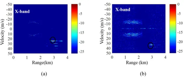
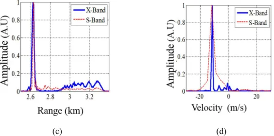
Finally, we have performed a detection of a non-cooperative helicopter using S- and X-bands concurrently. It was coincidentally flying over the building rooftop at lower velocity, which made easier to be precisely detected at both frequency ranges simultaneously. Fig. 11 displays the experimental results at 2.525 and 9.925 GHz in terms of Doppler map and normalized received power. An excellent agreement between the two bands has been observed, with a target detection at 2.65 km away from the transceiver and velocity of 11.86 m/s.
Brazilian Microwave and Optoelectronics Society-SBMO received 1 Oct 2018; for review 9 Nov 2018; accepted 16 Nov 2018 Brazilian Society of Electromagnetism-SBMag © 2018 SBMO/SBMag ISSN 2179-1074
(c)
(d)
Fig. 11. Helicopter detection at 2.525 and 9.925 GHz simultaneously: (a) Doppler map at 2.525 GHz, (b) Doppler map at 9.925 GHz, (c) Normalized received power as a function of range, (d) Normalized received power as a function of
velocity.
V. CONCLUSIONS
We have successfully proposed and demonstrated a dual-band radar system composed of a photonics-based transceiver and a Focal-Point/Cassegrain parabolic antenna. The antenna prototype presented gain of 23.75 dBi, side lobe level of -15.47 dB and 290 MHz bandwidth in the S-band. For X-Band, it provides gain of 24.5 dBi, side lobe level of -12 dB and 3.9 GHz bandwidth from 6.94 to 10.84 GHz. A FSbased subreflector has been conceived to be electromagnetic transparent for the S-band and act as a reflector at 9.925 GHz, enabling a simultaneous operation over the S- and X-S-bands. The antenna applicability has been validated by carrying out radar experiments on a building rooftop in Pisa, Italy. Non-cooperative aerial (airplanes and helicopters) targets have been detected at distances up to 2.9 km and velocities up to 40 m/s. Furthermore, experimental results of detections in the S- and X-bands have been shown in excellent agreement. Multi-spectral observations are considered potential to enhance radar resolution and sensitivity, by means of data fusion. As a final conclusion, the proposed radar system represents a technological solution for cost, footprint, weight and complexity reduction. As future works, we envisage the antenna usage for simultaneously detect and communicate in dual-use radar systems.
ACKNOWLEDGMENTS
This study was partially financed by Finep/Funttel Grant No. 01.14.0231.00, under the Radio Communications Reference Centre (CRR) project of the National Institute of Telecommunications (Inatel), Brazil, and the Coordenação de Aperfeiçoamento de Pessoal de Nível Superior - Brazil (CAPES) - Finance Code 001 and. Authors also thank the technical support from Keysight and financial support from CNPq, MCTI and FAPEMIG.
Brazilian Microwave and Optoelectronics Society-SBMO received 1 Oct 2018; for review 9 Nov 2018; accepted 16 Nov 2018 Brazilian Society of Electromagnetism-SBMag © 2018 SBMO/SBMag ISSN 2179-1074 [1] Y. Pei, Y. Chen, D. M. W. Leenaerts, and A. H. M. van Roermund, “A 30/35 GHz dual-band transmitter for phased
arrays in communication/radar applications,” inIEEE Journal of Solid-State Circuits, vol. 50, pp. 1629–1644, July 2015.
[2] V. Giammello, E. Ragonese, and G. Palmisano, “Transmitter chipset for 24/77-GHz automotive radar sensors,” 2010 IEEE Radio Frequency Integrated Circuits Symposium, pp. 75–78, May 2010.
[3] W. Wiesbeck, L. Sit, M. Younis, T. Rommel, G. Krieger, and A. Moreira, “Radar 2020: The future of radar systems,” in 2015 IEEE International Geoscience and Remote Sensing Symposium (IGARSS), pp. 188–191, July 2015.
[4] I. Sarkas, E. Laskin, J. Hasch, P. Chevalier, and S. P. Voinigescu, “Second generation transceivers for d-band radar and data communication applications,” in 2010 IEEE MTT-S International Microwave Symposium, pp. 1–1, May 2010. [5] P. G. et al., “A fully photonics-based coherent radar system,” Nature, vol. 507, pp. 341–345, March 2014.
[6] S. Melo, S. Pinna, A. Bogoni, I. F. da Costa, D. H. Spadoti, F. Laghezza,F. Scotti, and S. A. Cerqueira, “Dual-use system combining simultane- ous active radar communication, based on a single photonics-assisted transceiver,” in
2016 17th International Radar Symposium (IRS), pp. 1– 4, May 2016.
[7] R. Guida, S. W. Ng, and P. Iervolino, “S- and x-band sar data fusion,” in 2015 IEEE 5th Asia-Pacific Conference on Synthetic Aperture Radar (APSAR), pp. 578–581, Sept 2015.
[8] P. Xaypraseuth, R. Satish, and A. Chatterjee, “Nisar spacecraft concept overview: Design challenges for a proposed flagship dual-frequency SAR mission,” in 2015 IEEE Aerospace Conference, pp. 1–11, March 2015.
[9] S.-H. Hsu, Y.-J. Ren, and K. Chang, “A dual-polarized planar-array antenna for s-band and x-band airborne applications,” IEEE Antennas and Propagation Magazine, vol. 51, pp. 70–78, Aug 2009.
[10] M. Pachiyaannan and G. K. D. P. Venkatesan, “Dual-band UWB antenna for radar applications: Design and analysis,” in 2016 8th International Conference on Computational Intelligence and Communication Networks (CICN), pp. 196– 199, Dec 2016.
[11] C. S. Arismar, I. F. da Costa, S. Pinna, S. Melo, F. Laghezza, F. Scotti,P. Ghelfi, D. H. Spadoti, and A. Bogoni, “A novel dual-polarization and dual-band slotted waveguide antenna array for dual-use radars,” in 2016 10th European Conference on Antennas and Propagation (EuCAP), pp. 1–4, April 2016.
[12] T. H. Brandão, H. R. D. Filgueiras, S. A. Cerqueira, J. F. Mologni, and A. Bogoni, “Fss-based dual-band cassegrain parabolic antenna for radarcom applications,” in 2017 SBMO/IEEE MTT-S International Microwave and Optoelectronics Conference (IMOC), pp. 1–4, Aug 2017.
[13] T.H. Brandão, H.R.D. Filgueiras, A. A. C. Alves, S. Mello, Filippo Scotti, A. Bogoni and Arismar Cerqueira S. Jr., “Photonics Processing Radar System based on Dual-Band Cassegrain Parabolic Antenna (in Portuguese),” 18 SBMO - Simpósio Brasileiro de Microondas e Optoeletrônica e 13 CBMAG - Congresso Brasileiro de Eletromagnetismo (MOMAG 2018), Santa Rita do Sapucaí, 2018.
[14] I. F. da Costa, A. C. S., D. H. Spadoti, L. G. da Silva, J. A. J. Ribeiro, and S. E. Barbin, “Optically controlled reconfigurable antenna array for mm-wave applications,” IEEE Antennas and Wireless Propagation Letters, vol. 16, pp. 2142–2145, 2017.
[15] C. S. Arismar, I. F. da Costa, R. A. dos Santos, H. R. D. Filgueiras, and D. H. Spadoti, “Waveguide-based antenna arrays for 5G networks,” International Journal of Antennas and Propagation, 2018.
[16] S. Agahi; R. Mittra, “Design of a cascaded frequency selective surface as a dichroic subreflector,” International Symposium on Antennas and Propagation Society, Dallas, TX, May 1990.
[17] M.G. Floreani ; R.E. Zich ; G. Aulisio ; P. Besso ; A. Somma, “Design and experimental validations of a new FSS conformal subreflector structure for Cassegrain systems,” IEEE Antennas and Propagation Society International Symposium, Boston, MA, Jul. 2001.
[18] Te-Kao Wu, "Four-band frequency selective surface with double-square-loop patch elements," in IEEE Transactions on Antennas and Propagation, vol. 42, no. 12, pp. 1659-1663, Dec. 1994.
[19] J. Vardaxoglou, “Frequency Selective Surfaces: Analysis and Design”, Antennas series, Research Studies Press, 1997.
[20] R. Ulrich, “Far-infrared properties of metallic mesh and its complementary structure,” Infrared Physics, vol. 7, no. 1, pp. 37–55, 1967.
[21] B. A. Munk, “Frequency Selective Surfaces: Theory and Design,”John Wiley & Sons, 2005.
[22] B. Munk, R. Kouyoumjian, and L. Peters, “Reflection properties of periodic surfaces of loaded dipoles,” IEEE Transactions on Antennas and Propagation, vol. 19, pp. 612–617, Sep 1971.
[23] V. Agrawal and W. Imbriale, “Design of a dichroic cassegrain subreflector,” IEEE Transactions on Antennas and Propagation, vol. 27, pp. 466– 473, July 1979.
[24] C. Balanis, “Antenna theory: analysis and design”. 4th edn, Hoboken, NJ: Wiley, 2016. [25] C. Balanis, “Modern Antenna Handbook”John Wiley & Sons, Incorporated, 2008.