65
Transactions of the VŠB – Technical University of Ostrava, Mechanical Series No. 1, 2013, vol. LIX
article No. 1938
Luboš PEČENKA*, Matúš KALINA**, Radim HALAMA***
VERIFICATION OF ESPI STRESS ANALYSIS BY MEANS OF FEM
VERIFIKACE ESPI ANALÝZYNAP TÍ POMOCÍ MKP
Abstract
The main goal of this paper is verification of accuracy of ESPI strain sensor Dantec dynamics Q-100. ESPI is the digital holographic interferometry method for measuring small displacements and deformations. There is necessary to consider the isotropic material properties for stress calculations using the ESPI systems. All stress measurements were performed on simple shape specimens subjected to tension and bending. The experimental results obtained on the tensile testing machine Testometric will be compared with results from Finite element calculation.
Abstrakt
Hlavním cílem článku je ov ření přesnosti m řící metody ESPI pomocí snímače Q-100 od firmy Dantec dynamics. ESPI je digitální holografická interferometrická metoda pro m ření malých posunutí a deformací. Nap tí jsou následn vyhodnocena s uvážením izotropních vlastností materiálu. Všechna m ření byla provedena na jednoduchých vzorcích namáhaných tahem a ohybem. Vzorky byly testovány na zkušebním stroji Testometric, dosažené experimentální výsledky budou porovnány s numerickými výsledky, získanými metodou konečných prvků.
Keywords
ESPI, experimental stress analysis, measurement, FEM.
1 INTRODUCTION
Electronic speckle pattern interferometry is a full-field measuring technique which calculates the small displacements by means of a fringe pattern. The surface to be measured is illuminated by laser light from four different directions and the reflected light is recorded by a high resolution CCD-camera [1]. The deformations are recorded when any loads are applied. It is preferable to apply the load in steps and store the measured data at each load step [2]. Using the interference effects of the laser light, the surface displacement is measured with micro meter accuracy. Using digital analysis and correlation methods, the specimen displacements and deformations are calculated automatically from the changes in the pattern on the specimen surface. With known material properties ĚYoung’s modulus, Poisson ratio) the stress distribution can also be determined in the measured area. This paper shows some interesting results of 2D stress measurement by ESPI method using the commercial ESPI sensor Dantec dynamics Q-100 and compares them with results of performed finite element analyses.
*
Ing., Department of Mechanics of Material, Faculty of Mechanical Engineering, Technical University of Ostrava, 17.listopadu 15/2172, Ostrava, tel. (+420) 59 732 3290, e-mail: [email protected]
**
Ing., Department of Applied Mechanics and Mechatronics, Faculty of Mechanical Engineering, Technical University of Košice, Letná 9, Košice, e-mail: [email protected]
***doc. Ing., Ph.D., Department of Mechanics of Material, Faculty of Mechanical Engineering, Technical
66
2 TENSILE SPECIMEN
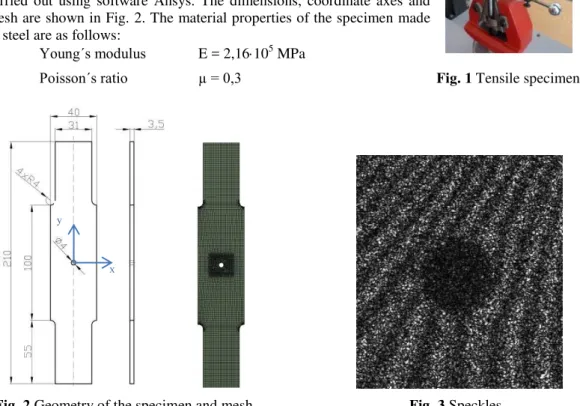
The electronic speckle pattern interferometer was used to investigate the tensile stress field of a steel plate in the presence of stress concentrations caused by a geometrical defect consisting of circular hole. The tests were realized on the universal testing machine Testometric M500-50CT (50 kN). Maximum test load ranges from 500 N to 6000 N. The experimental values of stresses can be employed for a comparison of the real behaviour of the specimen with the calculations obtained by finite elements. Numerical analysis (finite element analysis, FEA) has been carried out using software Ansys. The dimensions, coordinate axes and mesh are shown in Fig. 2.The material properties of the specimen made of steel are as follows:
Young´s modulus E = 2,16105 MPa
Poisson´s ratio µ = 0,3 Fig. 1 Tensile specimen
As first results, there are shown contours of first principal stress and displacement in y-direction in the region around the hole at the Fig. 4-5 and Fig. 7-8 respectively. The software ISTRAMS makes possible also determination of any stress component along a line. The principal stress distribution along x-axis (Fig. 2) is compared with FEA at the Fig. 6.
Fig. 4 Principal stress (ESPI)[MPa] Fig. 5 Principal stress (FEA) [MPa]
Fig. 2 Geometry of the specimen and mesh Fig. 3 Speckles
67
Fig. 6 Comparison of principal stress distribution obtained from FEA and ESPI
Fig. 7 Displacement in y-direction (ESPI)[µm] Fig. 8 Displacement in y-direction (FEA)[µm]
It is clear from the Fig. 7 and Fig. 8, that measured displacements contours in y-direction are very similar to the ones obtained from FEA. Very good repeatability of the measurement has been observed even for different load step values: 500 N, 1000 N and 2000 N.
3 BENDING SPECIMEN
As next case, ESPI technique is presented to measure 4-point bending of steel plate. Two forces of the same magnitude 2550 N and direction were applied on the top of the specimen. Supports in the y-direction are at the two ends of the specimen. The cross section of the specimen is a rectangle. The dimensions and coordinate axes are shown in Fig. 9.
Fig. 9 Geometry of the specimen Fig. 10 Bending specimen
Numerical analysis has been carried out again using software Ansys. These elastic constants were considered for the beam specimen in the analysis: Young´s modulus E = 2,1105 MPa and Poisson´s ratio µ = 0,3.
68
There are shown contours of principal stress and displacement in x-direction in the Fig. 11 and Fig. 12-13 to present results of the second experiment. Qualitative and quantitative agreement of the both approaches is obvious. The principal directions in the Fig. 11 from measurement also show the placement of neutral axis.
Fig. 11 Contours of principal stress (ESPI)[MPa]
Fig. 12 Displacement in x-direction (ESPI)[µm] Fig. 13 Displacement in x-direction (FEA)[µm]
4 CONCLUSIONS
This study has been focused on the verification of the stress and displacement contours measurement using ESPI. The holographic method has main advantages in contactless full field measurement with similar accuracy as strain gauges. Two test cases have been solved experimentally and by means of finite element method. All measurement and computations have been performed in elastic domain only. Realized tensile and bending experiments show good agreement with the numerical values. From the finite element analysis, it was possible to plot the normal stress contours that are very similar to the ones obtained by measurement. The method was also successfully applied to strain/stress contour measurements of a composite material [3].
ACKNOWLEDGEMENT
This paper has been elaborated in the framework of the project of specific research of Ministry of Education, Youth and Sports of the Czech Republic under No. SP2013/209.
REFERENCES
[1] TREBUŇA, F., ŠIMČÁK, F., Príručka experimentálnej mechaniky, TypoPress, Košice, 2007,
ISBN 970-80-8073-816-7
[2] TOUBAL, L., KARAMA, M., LORRAIN, B., Stress concentration in a circular hole in composite plate. Laboratoire Génie de Production, 2004, pp. 31-36.