Abstract
Important track degradation occurs in structure-embankment transitions, in which an abrupt change in track vertical stiffness arises, leading to a reduction in passengers comfort and safety. Although granular wedges are suggested by different railroad ad-ministrations as a solution to avoid these problems, they present some disadvantages which may affect track long-term performance. In this paper, a new solution designed with prefabricated rein-forced concrete slabs is proposed. The aim of this solution is to guarantee a continuous and gradual track vertical stiffness transi-tion in the vicinity of structures, overcoming granular wedges disadvantages. The aim of this study is to assess the performance of the novel wedge design by means of a 3-D FEM model and to compare it with the current solution.
Keywords
Transition wedges, granular wedges, track stiffness, railway infra-structure
New Transition Wedge Design Composed
by Prefabricated Reinforced Concrete Slabs
1 INTRODUCTION
In recent years, railways transport has suffered huge changes: the operational speed of trains and the loads hauled by them have been increased, and there has appeared a need to improve passen-gers’ comfort, to reach higher safety levels and to reduce maintenance costs. In railroad networks, there are some singular areas where these previous aspects are more critical. An example of these areas are the transition zones, such as bridge approaches, road crossings, ballastless to ballasted
Julia Real-Herráiz a Clara Zamorano-Martín b Teresa Real-Herráiz c Silvia Morales-Ivorra d
a Institute for Multidisciplinary
Mathe-matics, Polytechnic University of Valen-cia. Valencia, Spain. [email protected]
b Foundation for the Research and
Engi-neering in Railways.Madrid. Spain. [email protected]
c Institute for Multidisciplinary
Mathe-matics, Polytechnic University of Valen-cia. Spain. [email protected]
d Institute for Multidisciplinary
Mathe-matics, Polytechnic University of Valen-cia. Spain. [email protected]
http://dx.doi.org/10.1590/1679-78252556
tracks changes, culverts and tunnels. In these scenarios, track degradation is faster and maintenance costs result disproportionate, as stated by Li and Davis (2005), Teixeira (2003), Liu and Zhao (2013) and Shi et al. (2013). Within this context, Hyslip, et al. (2009) indicated that more than $110 million per year and more than $200 million per year were spent in Europe and USA, respec-tively, on track maintenance in transition zones. From these statements, it may be concluded that an extensive study of the performance of these areas is of utmost importance to minimize their de-terioration and to optimize maintenance works. Thus, in this paper, the transition areas placed in the vicinity of structures has been assessed.
As reported by Coelho et al. (2011), three causes may be responsible of the effects located in transition areas: (1) sharp track vertical stiffness variation between a track section built over an embankment and the adjacent section built over a structure, (2) relative settlements of the abut-ment soil and (3) geotechnical defects. It must be noted that these three causes are not independ-ent.
Furthermore, track differential settlements may cause significant increases on the accelerations registered inside of the vehicles, which should be avoided for the sake of passengers’ comfort. Re-garding the safety, sudden changes in the vertical track stiffness induce the damage of trains and infrastructures, which could lead to a serious risk of derailment (Insa et al. (2012)). Teixeira (2003) insisted on the need to limit the value of the track vertical stiffness in order to control these adverse effects in railway lines. In this study, a range of allowable stiffness was proposed: the maximum value depended on the safety and maintenance costs while the minimum was set by traction energy dissipation. Moreover, López et al. (2004) proposed an optimum range for track the vertical stiffness considering, on the one hand, the tamping and alignment operations costs and, on the other hand, energy expenditures in high-speed railroad networks.
According to the causes of damages in transition areas stated by Coelho et al. (2011), in the current study good compaction, good consolidation and good drainage of the soils have been sup-posed. Thus, the present paper is focused on: (1) the abrupt changes in track vertical stiffness and (2) the differential settlements, as the main cause of transition deterioration. As stated by Gallego et al. (2011), sudden changes in track vertical stiffness induce variations in the dynamic overloads generated in the rail-wheel contact and then transmitted to the track, so as enhancing the appear-ance of differential settlements in said section. The magnitude of the changes in dynamic loads de-pends on the train speed, the ratio between stiffness values, the soil damping and the transition length (Insa et al. (2012)). Moreover, differential settlements contribute to an increase of the dy-namic overloads as the train passes over them, as indicated by Gallego et al. (2012), thus generating a cyclical process of track damage.
Moreover, along the technical literature some additional measures to reduce variations of stiff-ness have been proposed by authors as Soriano et al. (1991), Li and Davis (2005), Gallego and López (2009), Coehlo et al. (2011), Insa et al. (2012) and, furthermore, in the IGP08 (2008) and UIC-719R (UIC 1994). These supplemental measures are:
Approaches slabs.
Soft pads under the rail on structure zone.
Rubber under ballast mat on structure zone.
Wooden or plastic ties on the stiff side of the transition.
Under sleeper pads on the stiff side of the transition.
Reductions of sleeper spacing or the use of extra-wide sleepers on the soft zone.
Two additional rails in the vicinity of the structure.
Geosintetics to reinforce the soil in abutments.
Stone columns or piles to reinforce the foundation and geogrids to reduce ballast settlements.
Treatment with cement of the track bed layer and the subballast layer.
It is important to point out that granular wedges present some disadvantages: important eco-nomic costs related to the granular material transportation, long periods of execution, difficult qual-ity control in the final product and influence of climatic conditions which can affect the construc-tion process. All these disadvantages could result in an undesirable poor long-term behavior of the granular wedge. With the aim of avoiding these disadvantages, a new transition wedge design, made by prefabricated slabs, will be proposed and its performance assessed.
Since the main objective of this study is to assess the vertical behavior of this novel transition design a 3-D dimensional numerical model has been developed to reproduce its performance. Then, the current paper is structured as follows: first of all, the new transition design will be described; then, the numerical FEM model developed to assess its behavior will be presented and, afterwards, results will be presented. Finally, conclusions will be drawn.
2 NEW TRANSITION WEDGE DESCRIPTION AND METHODOLOGY
In the present section, a new transition wedge design is presented, being its main goal to achieve a gradual vertical stiffness variation in the vicinity of structures. Novel transition wedges are made by prefabricated reinforced concrete slabs, whose dimensions are adaptable so as to fit with the needs of each particular situation (Figure 1).
The reinforced concrete slabs have been considered stacked properly, one above other, to build the transition wedge, and they must be aligned with the structure abutment and supported on a competent stratum. A wide range of configurations is allowed with this solution since it is possible to increase the number of floors of precast slabs in each case.
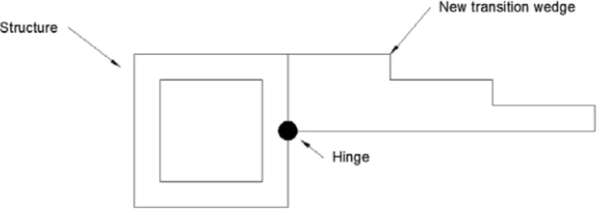
The dimensions of transition wedge are set depending on the vertical track stiffness variation existing in each single case. One example of the proposed transition wedge can be seen in Figure 2:
Figure 2: Example of the new transition wedge design
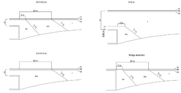
To assess the performance of the novel design, it has been compared to the ones proposed by the Spanish regulation IGP08, which divide the types of transitions in four groups depending on the distance between the top of the structure and the bottom of subballast layer (H), as depicted in Figure 3.
In order to achieve a continuous transition of stiffness between both stretches – over the struc-ture and over the embankment – different granular materials are commonly used in technical blocks to build the wedge. The slopes of these technical blocks are detailed in Figure 3, where ballast, sub-ballast and formation layer are respectively designated as B, SB and TB. Granular materials used in these transition wedges are granular material treated with cement (MT), granular material (MG) and the common material used in the embankment.
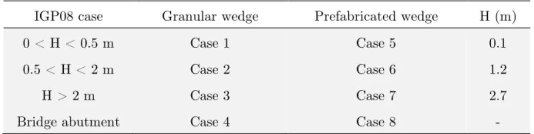
In this investigation, a total of eight cases have been studied. As detailed in Table 1, four cases have been analyzed to characterize the current granular transition wedges, and other four cases have been considered to analyze the new transition wedge. Bridge abutment and buried structures of rectangular external geometry have been the rigid elements considered.
IGP08 case Granular wedge Prefabricated wedge H (m)
0 < H < 0.5 m Case 1 Case 5 0.1
0.5 < H < 2 m Case 2 Case 6 1.2
H > 2 m Case 3 Case 7 2.7
Bridge abutment Case 4 Case 8 -
Table 1: Studied cases
Furthermore, two different prefabricated wedge configurations have been considered depending on the analyzed case. The wedge shown in Figure 4 has been used for the Case 7, in which the dis-tance between the top of the structure and the bottom of the subballast layer is higher than 2m:
Figure 4: Wedge implemented in Case 7 (Units in meters)
For the rest of cases, the new transition wedge adopted has been the transition indicated in Figure 5:
Figure 5: Wedge implemented in Cases 5, 6 and 8 (Units in meters)
Figure 6: New suggested wedge location and connection to the structure
The study of both transition wedges and the comparison between them has been performed by means of eight three-dimensional numerical models, one for each considered case. Finite elements method has been adopted since it allows studying the track as a complete system considering differ-ent elemdiffer-ents, material and boundary conditions, as reported by Ministerio de Fomdiffer-ento (1999). Moreover, this method has been successfully used in lots of railway investigations, as in Gallego and
López (2009), Gallego et al. (2011), Real et al. (2012) and Molatefi and Izadbakhsh (2013). Two
examples of the numerical models constructed in this research are shown in Figure 7.
Figure 7: Numerical model in Case 2 (left) and in Case 6 (right)
Comparison between granular and precast concrete transition wedges has been developed in terms of vertical displacements of the rail top. To do so, first of all, the optimium Young’s modulus of the soil, over which the new solution is placed, is obtained for each studied case. Then, since bearing capacity of the support soil needs to be improved in Cases 5, 6 and 8, a concrete pile system has been proposed and its implementation detailed. The pile system has been chosen instead of the use of granular material since its long-term performance does not fulfill the desired requirements, as stated in the introduction section.
3 NUMERICAL MODEL
Numerical models have been developed to characterize all the studied cases and to compare their behavior. In the current section, these models will be detailed.
With regard to the geometry, a Cartesian coordinate system has been used in the numerical models. The transversal direction is represented by the x-axis, the vertical direction by the y-axis and the longitudinal direction by z-axis. The cross section is considered as a simple track with a symmetric axis at plane X=0 (Montalbán et al. 2013). The length of the transition depends on H value (see Figure 3) and the height of the embankment (IGP08 2008). In this research, total model length is 46.5 meters, including 78 sleepers spaced 0.6 meters.
The cross section variables considered take typical values for high-speed railway tracks, as indi-cated in Ministerio de Fomento (1999). Ballast, subballast, and formation layers are 40, 30 and 60 cm thick, respectively; shoulders are 50 cm length and the slopes are 3H:2V in the ballast layer and in the embankment.
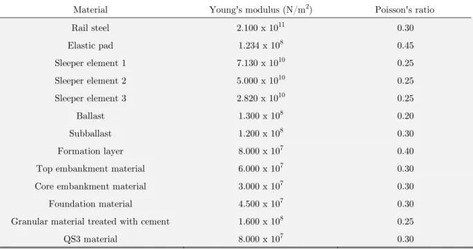
An elastic, isotropic and lineal model has been assumed to characterize the rails, elastic pads, sleepers, common granular material, granular material treated with cement and soil material (Gallego and López 2009, Shan, Albers and Savidis 2013, Real et al. 2014). The material parameters used in the models are shown in Table 2.
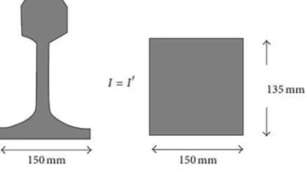
All the elements of the track have been modeled taking into account the simplifications pro-posed in the Recommendations by Ministerio de Fomento (1999). A parallelepiped element is con-sidered as a simplification to obtain an equivalent UIC 60 rail in which vertical inertia (X-axis) is equal to vertical inertia of the real one (Montalbán, et al. 2014b) (see Figure 8). The rail pad is modeled with new dimensions to be compatible with the rails and sleepers geometry and ensuring that the vertical stiffness is equivalent to the vertical stiffness provided by the manufacturer. For this purpose, the rail pad surface is equal to the contact surface between the rail and the sleeper and the rail pad thickness is considered equal to 50 mm. Thus, the Young’s modulus is modified to maintain the compressive stiffness equal to the real one (Montalbán et al. 2013). Finally, the sleeper is modeled as simplified parallelepiped elements (see Figure 9). The real cross sections variations are taken into account since the parallelepiped sleeper is implemented keeping the real longitudinal bending properties, like in Real et al. (2012).
Figure 9: Real and modeled sleeper
Material Young's modulus (N/m2) Poisson's ratio
Rail steel 2.100 x 10¹¹ 0.30
Elastic pad 1.234 x 10⁸ 0.45
Sleeper element 1 7.130 x 10¹⁰ 0.25
Sleeper element 2 5.000 x 10¹⁰ 0.25
Sleeper element 3 2.820 x 10¹⁰ 0.25
Ballast 1.300 x 10⁸ 0.20
Subballast 1.200 x 10⁸ 0.30
Formation layer 8.000 x 10⁷ 0.40
Top embankment material 6.000 x 10⁷ 0.30
Core embankment material 3.000 x 10⁷ 0.30
Foundation material 4.500 x 10⁷ 0.30
Granular material treated with cement 1.600 x 10⁸ 0.25
QS3 material 8.000 x 10⁷ 0.30
Table 2: Material characteristics considered in the models
The boundary conditions in the three directions are defined following Ministerio de Fomento (1999) and Montalbán, et al. (2013). In this way, the bordering planes present perpendicular movement constrained. Moreover, the surfaces of the granular material slopes are completely free.
Additionally, tensional discontinuities appear in the contact between concrete and granular ma-terial due to their different stiffness. The sleeper-ballast contact zones have a high concentration of stresses. In order to model these zones, bounded degrees of freedom are used (Ministerio de
Fomen-to 1999, Montalbán et al. 2014b). Different nodes in the contact surface are introduced for each
granular materials is adherent and they share the nodes at the contact surface (Montalbán et al. 2014a).
The load applied considers both the static load due to the vehicle passage and the dynamic ef-fects induced by irregularities, in accordance with Montalbán et al. (2013). Eisenmann’s formulation is the method applied to take into account these overloads (López 2006, Real et al. 2012). This for-mulation is based on Eq. (1).
̅ 6 (1)
In the calculation, the speed (v) is 250 km/h, the vehicles static load are 17 t/axe (Qn), the sta-tistical security coefficient is t=2, corresponding to the percentile 95.5%, the track quality factor is
s
=0.2, due to the good conditions of the track. As a result of that, the amplified load consideredvalue is 27.2 t/axle.
The load is considered as a distributed load regarding the pass of a train formed by 8 axles in a static analysis. This load is distributed on a total length of 70 sleepers (common high-speed train length). Distributed load is selected since a complete behavior of the transition area is studied.
The validation and calibration of the track model with the granular wedge and with the prefab-ricated one were carried out using real data of vertical deflections from transitions areas obtained from measurements campaigns.
4 RESULTS
Vertical displacements of the rail top obtained are presented in different sections. Firstly, vertical displacements of the rail are analyzed considering different Young’s moduli of the support soil under the prefabricated wedges and compared to the results in granular wedges. After this comparison, the optimum Young’s modulus for the supported soil is elected in each case. Secondly, a comparison of the vertical displacement of the rail top between the granular wedge and the new transition wedge with optimum Young’s modulus of the support soil is made. The goal of this process is to test the behavior of these two types of wedges. Finally, a pile support system is elected. As an ex-ample, it is pre-designed for Case 8.
4.1 Vertical Displacements of the Rail Top
The main aim of this part is to compare vertical displacements of the rail top obtained with granu-lar and prefabricated wedges. Different Young’s moduli are considered in the support soil of the prefabricated wedges in order to determine the optimum for each prefabricated case.
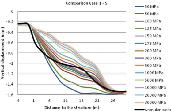
Figure 10: Vertical displacements in Case 1 and Case 5
Figure 12: Vertical displacements in Case 3 and Case 7
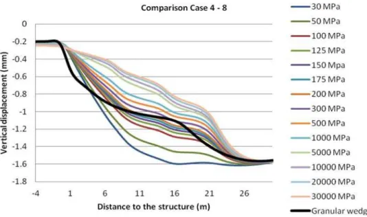
Figure 13: Vertical displacements in Case 4 and Case 8
In addition, vertical displacements of the rail top over the new proposed wedge can be seen in Figures 10-13. Different results are presented for the prefabricated wedge cases depending on the soil Young’s modulus considered. With the results obtained, it can be deduced that higher values of Young’s modulus cause lower displacements of the rail. Once these figures have been analyzed, the optimum value of the Young’s modulus for the support soil is selected. It is chosen considering simi-lar performance than granusimi-lar wedges. This optimum value suggested for each case is shown in Table 3:
Case Optimum soil Young’s modulus (MPa)
Case 5 175
Case 6 150
Case 7 30
Case 8 175
Table 3: Optimum soil Young’s modulus for each prefabricated case
The values presented in Table 3 have been estimated using a FEM model. The only purpose of this is to demonstrate that different support systems are required for some prefabricated wedges (Cases 5, 6 and 8) to achieve a global performance similar to granular wedges.
4.2 Comparison Between Granular and Prefabricated Wedges
The obtained vertical displacements of the rail top in granular and prefabricated wedges are com-pared in order to test the correct structural behavior of the new studied wedges. Only optimum Young’s modulus proposed in the support soil is considered in each prefabricated case, as shown in next figures.
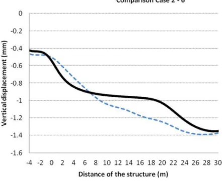
Figure 15: Vertical displacements in Case 2 and Case 6
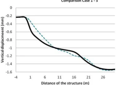
Figure 17: Vertical displacements in Case 4 and Case 8
It can be observed in Figures 14 to 17 that an adequate vertical displacement transition appears when the granular wedge is chosen. This transition is more continuous and uniform as H increases. As indicated in said figures, the behavior of the granular wedge is improved in all cases since vertical displacements of the rail top are more continuous in prefabricated than in granular transi-tions. As can be observed, the vertical displacements of the rail top are different between the Cases 2-3 and Cases 6-7. It is due to the different granular materials located just on the rigid structure which modify the track vertical stiffness in this zone.
4.3 Support System
As shown in the results, the support soil must have an elevated Young’s modulus with small H values. These results indicated that a support system is needed in the analyzed cases except in Case 7, in which the prefabricated wedge can directly rest on the soil. In this research, treated granular material is not considered as a possible solution to obtain the required stiffness under the prefabri-cated wedges. This solution is focused on providing a good long-term performance with prefabricat-ed elements exclusively. Since this long performance cannot be guaranteprefabricat-ed in the case of the granu-lar materials treated with cement, the authors have not considered this solution.
After this consideration, a pile system is chosen as the option to support the prefabricated wedge in Cases 5, 6 and 8.
Figure 18: Pile system proposed in the pre-design
In this step, the process to obtain the pre-design is indicated. Firstly, the total load resisted by the slabs and pile system (Ntotal) has been calculated. Secondly, the load endured by the pile system
(Npiles) has been obtained. To calculate it, Eq. (2) has been used:
(2)
In this equation, Nslabs is the load supported by the slabs, Npiles is the load resisted by the pile
system, so is the vertical displacement of the rail top considering a support soil with a Young’s
modulus equal to 30MPa and s is the vertical displacement of the rail top produced when the soil under the prefabricated wedge has the optimum Young’s modulus.
Finally, the load resisted by one pile (Npile) can be estimated dividing the Npiles per the total
num-ber of piles considered. The results obtained are shown in Table 4.
x = 7.2 m x = 14.4 m
so (mm) -1.170 -1.563
s (mm) -0.857 -1.121
so/s (%) 0.268 0.283
Ntotal (kN) 3600.000 3600.000
Nslab (kN) 2634.131 2581.178
Npiles (kN) 965.869 1018.822
Npile (kN) 241.467 254.706
The total length and the diameter of the piles can be analyzed considering the value of Npile;
geotechnical characteristics of the existing soils beneath the wedge and the procedure indicated by Ministerio de Fomento (2011). This procedure is based on the concept that the total load in a pile must be less than or equal to the total shaft resistance and the total toe resistance. This concept is indicated in Eq. (3) and it has been considered as the pre-design equation to obtain the length and diameter of the pre-designed pile.
(3)
In this equation, Npile is the load resisted for one pile, Nshaft is total shaft resistance and Ntoe is total toe resistance.
To obtain Nshaft and Ntoe, unit shaft and unit toe resistance must be calculated considering the geotechnical characteristics of the embankment soil and the natural soil. The embankment ma-terial is considered as a QS2 mama-terial and the natural soil characteristics are obtained applying the Standard Penetration Test (SPT) indicated in the UNE EN ISO 22476-3:2006 standard (2006).
Considering the procedure indicated by Ministerio de Fomento (2011), unit shaft resistance in the embankment soil part is obtained by the Eq. (4):
(4)
In this equation, c is the material cohesion, is the thrust at rest coefficient, is the friction angle between pile and soil and is the vertical effective pressure at the considered level.
Considering that the material cohesion (c) is equal to 10 kPa, is equal to 0.3 (Ministerio de
Fomento 2011) and =66.667 kPa, the unit shaft resistance in embankment material is equal to 30 kPa.
After considering the embankment material, the foundation material is studied. The procedure based in the static penetration test indicated by Ministerio de Fomento (2011) is elected to obtain the unit shaft resistance and the unit toe resistance.
The unit shaft resistance is obtained by the Eq. (5) taking into account that there exists a clay-ey soil.
. (5)
Considering a unit SPT toe resistance ( ) by the static penetration test (UNE-EN ISO 22476-3:2006) equal to 3340 kPa, the unit shaft resistance in the foundation part is 66.8 kPa.
The unit toe resistance and total toe resistance is not considered since the strains are small and this resistance is not considered.
Different diameters are studied to obtain the length results shown in next figure:
Figure 20: Pile diameter and length dimensions
5 CONCLUSIONS
This paper presents a new transition wedge design formed by prefabricated reinforced concrete slabs. The special stepped shape of the novel wedge allows smooth track vertical stiffness transition values from one transverse section to another in the proximity of structures, as can be seen in the results section. The use of prefabricated elements minimizes the construction costs, reduce the peri-ods of executions and achieve better quality control.
Finite element method has been used to demonstrate the appropriate vertical behavior, as in previous investigations (Gallego and López 2009, Shan, Albers and Savidis 2013). Eight different cases have been developed depending on the H parameter and the type of wedge analyzed. Different numerical models have been used to study each considered case.
After the study, some remarks can be drawn:
Granular wedges provide an interesting solution to avoid the sharp variation in vertical track stiffness in the vicinity of structures.
The new wedges proposed in this paper improve the performance of the commonly used
granular wedges.
The improvement of the support soil bearing capacity could be necessary when H<2m. Thus,
concrete pile system is the solution proposed to avoid the drawbacks of the use of granular natural materials and granular treated materials.
References
Coehlo, B., Hölscher, P., Priest, J., Powrie, W. and Barends, F. (2011). An assessment of transition zone perfor-mance. Proceedings of the Institution of Mechanical Engineers. Part F: Journal of rail and rapid transit, 225( F2), 129-139.
Gallego, I. and López, A., (2009). Numerical simulation of embankment-structure transition design. Proceedings of the Institution of Mechanical Engineers, Part F: Journal of Rail and Rapid Transit, 223(4), 331-343.
Gallego, I., López, A., Vieira, E. and Rivas, A. (2012). Design of embankment-structure transitions for railway infrastructure. Procedings of the Institution of Civil Engineers - Transport, 165(1), 27-37.
Gallego, I., Muñoz, J., Rivas, A. and Sánchez-Cambronero, S. (2011). Vertical track stiffness as a new parameter involved in designing high-speed railway infrastructures. Journal of transportation engineering, 137(12), 971-979. Hyslip, J.P., Li, D. and McDaniel, C.R: (2009). Railway bridge transition case study. 8th International Conference on the Bearing Capacity of Roads, Railways and Airfields. Bearing capacity of roads, railways and airfields. Champaign. USA. June -July.
IGP08. (2008). Instrucciones generales para proyectos de plataforma IGP. Adif. Madrid, Spain.
Insa, R., Salvador, P., Inarejos, J. and Roda, A. (2012). Analysis of the influence of under sleeper pads on the railway vehicle/track dynamic interaction in transition zones. Proceedings of the Institution of Mechanical Engineers. Part F, Journal of rail and rapid transit. 226(F4), 409-420.
Li, D. and Davis, D. (2005). Transition of railroad bridge approaches. Journal of geotechnical and geoenvironmental engineering, 131(11), 1392-1398.
Liu, Y. and Zhao, G. (2013) Study of Reasonable Length of Ballasted-CRTS II Ballastless Track Transition Section on High-speed Railway Bridge. Conference on Structures and Building Materials. Construction and urban planning. Book Series: Advanced Materials Research, Guizhou. China. March.
López, A. (2006). Infraestructura Ferroviaria. Ediciones UPC, Jordi Girona, Barcelona, Spain.
López, A., Teixeira, P F. and Robusté, F. (2004). High speed and track deterioration: the role of vertical stiffness of the track. Proceedings of the Institution of Mechanical Engineers. Part F, Journal of rail and rapid transit, 218(1), 31-40.
Ministerio de fomento/Secretaría de estado de Infraestructuras y Transportes, (1999). Recomendaciones para el proyecto de plataformas ferroviarias. Centro de publicaciones, Madrid, Spain.
Ministerio de fomento/Secretaría de estado de planificación e infraestructuras, (2011). Guía de cimentaciones en obras de carretera. Centro de publicaciones, Madrid, Spain.
Molatefi, H. and Izadbakhsh, S. (2013). Continuous rail absorber design using decay rate calculation in FEM.
Structural Engineering and Mechanics. 48(4).
Montalbán, L., Real, J. and Real, T. (2013). Mechanical characterization of railway structures based on vertical stiffness analysis and railway substructure stress state. Proceedings of the Institution of Mechanical Engineers. Part F: Journal of Rail and Rapid transit, 227(F1), 74-85.
Montalbán, L., Real, J., Zamorano, C. and Real, T. (2014a). Design of a new high lateral resistance sleeper and performance comparison with conventional sleepers in a curved railway track by means of finite element models.
Latin American Journal of Solids and Structures, 11(7), 1238-1250.
Montalbán, L., Zamorano, C., Palenzuela, C. and Real, J. (2014b). Analysis of the influence of cracked sleepers
under static loading on ballasted railway tracks. The Scientific World Journal.
http://dx.doi.org/10.1155/2014/363547
Real, J., Zamorano, C., Hernández, C., Comendador, R and Real, T. (2014). Computational considerations of 3-D finite element method models of railway vibration prediction in ballasted tracks. Journal of vibroengineering, 16(4), 1709-1722.
Shan, Y., Albers, B. and Savidis, S. (2013). Influence of different transition zones on the dynamic response of track-subgrade systems. Computers and Geotechnics, 48(1), 21-28.
Shi, J., Burrow, M., Chan, A. and Wang, Y. (2013). Measurements and simulation of the dynamic responses of a bridge-embankment transition zone below a heavy haul railway line. Proceedings of the Institution of Mechanical Engineers. Part F, Journal of rail and rapid transit, 227(F3), 254-268.
Soriano, A., Serrano, C., Sánchez, F. (1991). Transition Wedges for High-Velocity Railroad Structures. 10th European conf. of soil mechanics and foundation engineering. Deformation of soils and displacements of structures. Florence. Italy. May.
Teixeira P. (2003). Contribución a la reducción de los costes de mantenimiento de vías de alta velocidad mediante la optimización de su rigidez vertical. PhD Thesis, Universitat Politécnica de Catalunya, Barcelona, Spain.