IJCSMS International Journal of Computer Science and Management Studies, Vol. 12, Issue 02, April 2012 ISSN (Online): 2231-5268
www.ijcsms.com
IJCSMS www.ijcsms.com
147
1Sonia Chaudhary, 2Divya Madaan , 3Susheel Kumar
1
M.tech. Scholar, Jind Institute Of Engineering & Technology, JIND
2
M.tech. Scholar, Jind Institute Of Engineering & Technology, JIND
3
Associate Professor, Jind Institute Of Engineering & Technology, JIND
Abstract
Shuffle-exchange networks (SENs) have been widely considered as practical interconnection systems due to their size of its switching elements (SEs) and uncomplicated configuration. SEN is a network among a large class of topologically equivalent multistage interconnection networks (MINs) that includes omega, indirect binary n-cube, baseline, and generalized cube. In this paper, SEN with additional stages that provide more redundant paths are analyzed. A common network topology with a 2×2 basic building block in a SEN and its variants in terms of extra-stages is investigated. Finally terminal reliability of SEN, SEN+, SEN+2 are analyzed.
Keywords: Interconnection; Multistage; Networks;
Reliability; Fault tolerant; Shuffle exchange; Stages; Switching elements.
I.
INTRODUCTION
Interconnection networks play a major role in the performance of modern parallel computers. These networks can provide the communication in a parallel processing system consisting of a large number of processors that are working together to perform a single overall task. For large multiprocessor systems, the shared bus and the crossbar switch represent the extremes in interconnection schemes. The shared bus is inexpensive, but it is too slow and has limited bandwidth when a large number of processors must rely on it for communication.. At the other extreme, the crossbar switch provides high bandwidth and fastest possible communication speed, but its cost grows with the square of number of processors.
Multistage interconnection networks (MIN) provide a compromise between the shared bus and the crossbar
switch. These networks are designed to provide fast and efficient communication at a reasonable cost.
MINs consist of layers of switching elements (SEs) with a specific topological pattern. These networks provide interconnection between the set of processors (inputs) and the set of memory modules (outputs). They fall within the category of indirect network as they rely on intermediate elements to provide the interconnection between the input and output elements. It has been extensively used in both circuit switching and packet switching networks with the introduction of buffered switch .These include multiprocessor and communication network environments such as Ultra computer , IBM RP3,
ATM switches, and optical network. The number of stages, interconnection topology, and the type of SEs used in the network configuration differentiate each MIN fault tolerant. Examples of the widely used MINs include: shuffle Exchange network (SEN), Gamma network, extra-stage Gamma network, delta network, Tandem – Banyan network.
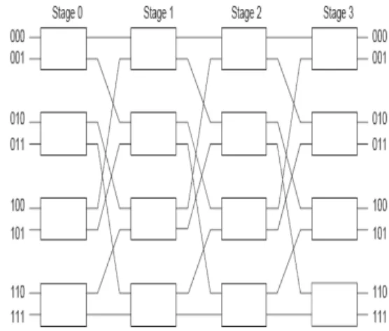
Due to the size of its SE and uncomplicated configuration of SEN as shown in Fig.1, it is one of the most commonly used MINs. Regular multi-stage interconnection networks have an equal number of switching elements per stage; as a result they may impose equal time delay to all the requests passing through them .
IJCSMS International Journal of Computer Science and Management Studies, Vol. 12, Issue 02, April 2012 ISSN (Online): 2231-5268
www.ijcsms.com
IJCSMS www.ijcsms.com
148
assess the effect of additional stages on SEN reliability.
II.
DESCRIPTION OF SEN,
SEN+, SEN+2
While we have chosen to analyze the SEN, this work can be extended to many other MINs since the SEN is just one network in large class of topological equivalent MINs that include the Omega, indirect binary-n cube, baseline, and generalized cube.
A 2x2 switching element (SE) is the basic component of the SEN. The SE can either transmit (T) the inputs directly through itself or exchange (X) the inputs. A SEN is a unique path MIN [13, 12]. Therefore, there is only a single path between a particular input output pair. In this type of network, all SEs are critical and assumed as series connection. The SE can either transmit the inputs straight through it or has cross connections. The number of switches per stage, the number of links and the connection between stages are consistent. An eight input / eight-output SEN with three stages, 12 switches (SEs), and 32 links as shown in Fig.1.
Figure 1: 8×8 Shuffle-Exchange Network (SEN).
A SEN+ is an N×N SEN with an additional stage. The SEN+ system has N inputs and N outputs, with two paths between each source–destination pair. It has n = log2N+1 stages and each stage has N/2 SEs. In general, the switch complexity for the N×N SEN+ is N/2(log2N+1). Thus, the additional cost of the SEN+ is N/2 switches or a fractional increase of 1/log2N, which is small for a large N. An example of the 8×8 SEN+ is demonstrated by Fig.2. The addition of an extra-stage to the SEN allows two paths for communication between each source and destination. While the paths in the first and the last stages of the SEN+ are not disjoint, the paths in the intermediate stages do disjoint links traverse. So
the path redundancy in the SEN+ is achieved at the expense of an additional stage to the SEN.
Figure 2: 8×8 SEN with an Extra-Stage (SEN+).
As a comparison to SEN and SEN+, a SEN with two additional stages (SEN+2) is presented [11], and the reliability is evaluated. In general, a SEN+2 consists of N inputs and N outputs, N/2 SEs per stage, log2N+2 stages, and (N) (log2N+3)
links. The network complexity is defined as the total number of SEs in the MIN, that is, (N/2)(log2N+2)
which is 20 SEs for an 8×8 SEN+2 shown in Fig.3.The number of terminal paths between an input and an output switches will be increased to 2k by adding k extra stages to the SEN. This is also true for broadcast network. The additional k stages will create 2k broadcast paths between a particular source and all destinations. Therefore, a SEN is a (2k-1) fault tolerant. For the 8×8 case, the terminal paths and the broadcast paths of the SEN+ and SEN+2 are 2 and 4 respectively.
IJCSMS International Journal of Computer Science and Management Studies, Vol. 12, Issue 02, April 2012 ISSN (Online): 2231-5268
www.ijcsms.com
IJCSMS www.ijcsms.com
149
III.
TERMINAL RELIABILITY
OF SEN, SEN+, SEN+2
Terminal reliability is defined as the probability of successful communication between an input and an output switches. In this section, terminal reliability of SEN, SEN+ and SEN+2 is evaluated for the 8×8 network. The SEN is a unique-path MIN that has N input switches and N output switches and n stages, where n = log2N Each stage consists of N/2 interchange boxes, where each box being controlled individually through routing tags. An 8×8 SEN with three stages has 12 SEs and 32 links.
Let r be the probability of a switch being operational. Since these networks are unique-path MIN, the failure of any switch will cause system failure, so from the reliability point of view, there islog2N SEs in series for each terminal path.
Hence, the terminal reliability of an N×N regular network is given by
Rt (Network) =(r) log2N.
As there is only a single path between a particular input Si, i = 1, 2, 3, 4, and a particular output in the SEN so the terminal reliability for N =8 is given by
Rt (SEN) =r3
SEN+ is a two-path MIN derived from the SEN by adding an extra-stage. Figure 2 shows an 8×8 SEN+ with four stages consisting of 16 SEs and 40 links. Since the SEN+ is a two-path MIN, there are two distinct paths between a particular input and output pair. From the reliability point of view, this system can be represented as a parallel system path, consisting of (log2N)-1 SEs each where each path is
connecting the input and output SE in series. Hence the terminal reliability of an N×N SEN+ is given by
Rt (SEN+) = (r) 2(1-(1-r (log2N)-1)2).
By adding an extra-stage to the 8×8 SEN, the number of connecting paths between any input and output switches will increase to two. Therefore, the terminal reliability of the 8×8 SEN+ is higher than that of the 8×8 SEN. From above equation, the terminal reliability of the SEN+ for N = 8 is given by
Rt (SEN+) = (r) 2(1-(1-r2)2) =2(r) 2 -(r) 6
An 8×8 SEN+2 having four SEs per stage, five stages, and 48 links as demonstrated in Figure 3. It is observed that there are four terminal paths between any pair of input Si (i = 1, 2, 3, and 4) and output Di.
Suppose that the position of a SE i in stage j is represented by SEi,j. Since there are 20 SEs in the
8×8 SEN+2 and five stages (0, 1, 2, 3, and 4), the SEs are numbered from SE0,0, SE1,0,..., SE2,4, SE3,4. As
an example, the terminal reliability between SE0,0 and
SE0,4 is examined as shown in Figure 4.3. The
terminal reliability of the 8×8 SEN with two additional stages for N =8 is
Rt (SEN+2) = r2∑ ci r (2N’-i) (1-r) i where i = 0 to 8
= r10 + 2r9 (1-r) + 8r8(1-r)2 + 8r7 (1-r)3 + 2r7 (1-r)2+ 4r6(1-r)3 + 4r6(1-r)2 + 4r5(1-r)2
IV.
EXPERIMENTAL RESULTS
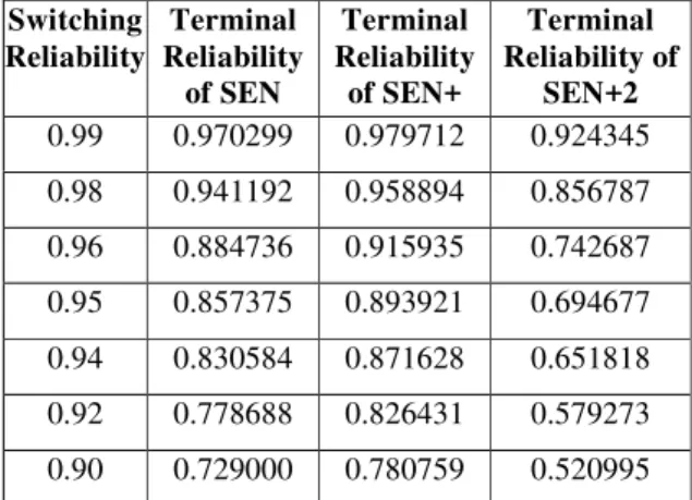
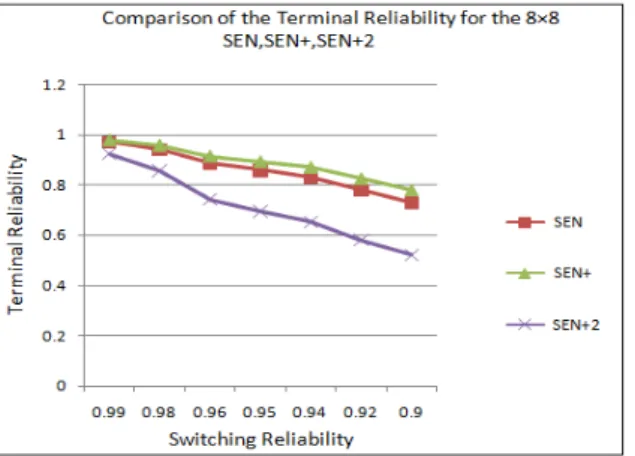
The comparison of the SEN, SEN+ and SEN+2 for the 8×8 networks is presented in Table 4. From Figure 4 it is clear that the terminal reliability of the SEN+ is the highest whereas the terminal reliability of SEN+2 is the lowest among these three networks. Therefore, there is not a direct relation between additional paths and increase in terminal reliability because the additional paths may increase the links complexity of the network, leading to a higher failure. Hence, it is concluded that adding one additional stage to the SEN is more efficient way to improve terminal reliability rather than two stages.
Table 4: Comparative Terminal reliability of SEN, SEN+ and SEN+2
Switching Reliability
Terminal Reliability
of SEN
Terminal Reliability
of SEN+
Terminal Reliability of
SEN+2
0.99 0.970299 0.979712 0.924345
0.98 0.941192 0.958894 0.856787
0.96 0.884736 0.915935 0.742687
0.95 0.857375 0.893921 0.694677
0.94 0.830584 0.871628 0.651818
0.92 0.778688 0.826431 0.579273
IJCSMS International Journal of Computer Science and Management Studies, Vol. 12, Issue 02, April 2012 ISSN (Online): 2231-5268
www.ijcsms.com
IJCSMS www.ijcsms.com
150
Figure 4: Terminal reliability graph of the 8×8 SEN, SEN+, SEN+2
V.
CONCLUSION
In this thesis Reliability analysis of regular multistage interconnection network namely SEN has been done. With the addition of one and two extra stages more regular MINs namely SEN+, SEN+2 are derived from SEN. As measures of network performance, the terminal reliability of all three networks have been evaluated. From the reliability analysis the following conclusion has been made:
Addition of one stage to any of SEN network provides higher reliability in terms of terminal reliability than the addition of two stages in the corresponding network.
VI.
REFERENCES
[1] Agrawal D. P., “Testing and Fault Tolerance of Multistage Interconnection Networks”, IEEE Transactions on Computers, April 1982, pp. 41-53. [2] Adams G. B., Agrawal D. P., Siegel H. J., “A Survey and Comparison of Fault- tolerant Interconnection Networks”, IEEE Transactions on Computers, June
1987, pp. 14-27.
[3] Adams G. B., Siegel H. J., “The Extra Stage Cube: A Fault-Tolerant Interconnection Network for Super systems”, IEEE Transactions on Computers, vol. 31, no. 5, May 1982, pp. 443-454.
[4]Bansal P.K., Singh K., Joshi R.C., “Quad Tree: A Cost-Effective Fault-Tolerant Multistage Interconnection Network”, Proceedings of IEEE International Conference INFOCOM, 1992, pp. 1.1-1.7.
[5] Gunawan I., Palaniappan S., Sien l. C., “Extra-Stage Cube Network Reliability Estimation Using Stratified Sampling Monte Carlo Method” Engineering e- Transaction, University of Malaya, vol.1, no.1, March 2006, pp.13-18.
[6] Bansal P.K., Singh K., Joshi R.C., “Routing and path length algorithm for a cost-effective four-tree Multistage Interconnection Network”, International Journal of Electronics, vol. 73, no.1, 1992, pp. 107-115.
[7] Bhogavilli S. K., Abu-Amara H., “Design and Analysis of High-performance Multistage Interconnection Networks”, IEEE Transactions on Computers, vol. 46, no. 1, January 1997, pp. 110 -117.
[8] Bhuyan L. N., Yang Q., Aggarwal D. P., “Performance of Multiprocessor Interconnection Networks”, IEEE Journals of Computer, February 1989, vol. 22, no. 2, pp. 25-37.
[9] Blake J. T., Trivedi K. S., “Reliabilities of Two Fault-Tolerant Interconnection Networks”, Proceedings of IEEE 18th International Symposium on Fault-tolerant Computing, 1988, vol. 22, no. 2, pp. 300-305.
[10] Blake J. T., Trivedi K. S., “Multistage Interconnection Network Reliability”, IEEE Transactions on Computers, 1989, vol. 38, no. 11, pp. 1600–1604.
[11] Gunawan I., “Reliability analysis of Shuffle Exchange Network Systems”, Reliability Engineering and System Safety, October 2008, pp. 271-276.
[12] Trahan J.L., Wang D.X., Rai S., “Dependent and Multimode Failures in Reliability Evaluation of Extra-stage Shuffle-exchange MINs”, IEEE Transactions on Reliability, 1995, vol. 44, no.1, pp. 73–86.
[13] Menezes B.L., Bakhru U., “New bounds on the Reliability of Augmented Shuffle-Exchange Networks, IEEE Transactions on Computers, 1995, vol. 44 no.1, pp.123–129.
[14] Hwang K., Bridges F.A., “Computer Architecture and Parallel processing”, McGraw Hill book company, New York, 1985.
[