Abstract
Crashworthiness is one of the main concerns in civil aviation safety particularly with regard to the increasing ratio of carbon fiber reinforced plastic (CFRP) in aircraft primary structures. In order to generate dates for model validations, the mechanical properties of T700/3234 were obtained by material performance tests, and energy-absorbing results were gained by quasi-static crushing tests of composite sinusoidal specimens. The correctness of composite material model and single-layer finite element model of composite sinusoidal specimens were verified based on the simulation results and test results that were in good agreement. A typical civil air-craft fuselage section with composite sinusoidal specimens under cargo floor was suggested. The crashworthiness of finite element model of fuselage section was assessed by simulating the vertical drop test subjected to 7 m/s impact velocity, and the influences of different thickness of sub-floor composite sinusoidal specimens on crashworthiness of fuselage section were also analyzed. The simula-tion results show that the established finite element model can accurately simulate the crushing process of composite sinusoidal specimens; the failure process of fuselage section is more stable, and the safety of occupants can be effectively improved because of the smaller peak accelerations that was limited to human toler-ance, a critical thickness of sub-floor composite sinusoidal speci-mens can restrict the magnitude of acceleration peaks, which has certain reference values for enhancing crashworthiness capabilities of fuselage section and improving the survivability of passengers.
Keywords
Crashworthiness; finite element method; composite sinusoidal spec-imens; energy-absorbing characteristic; fuselage section; failure modes; acceleration responses.
Crashworthiness Analysis and Evaluation of Fuselage
Section with Sub-floor Composite Sinusoidal Specimens
H.L. Mou * T.C. Zou Z.Y. Feng J. Xie
Tianjin Key Laboratory of Civil Aircraft Airworthiness and Maintenance, Civil Aviation University of China, Tianjin, China
Author email:[email protected]
http://dx.doi.org/10.1590/1679-78252446
1 INTRODUCTION
Crashworthiness design, verification and airworthiness certification of transport category airplanes are significantly important for civil aviation safety, and the survivability of passengers and crews can be further improved through the crashworthiness design of aircraft, such as the structures of aircraft fuselage section, cabin layout and internal facilities (Abramowitz, 2002; Jackson, 2002; Jackson, 2008; Xue, 2014). However, there are new demands and huge challenges for the crashwor-thiness design, verification and airworcrashwor-thiness certification of composite aircraft structures with the extensive application of composite structures, due to the complex failure mechanisms, the energy-absorbing characteristic and crushing process of composite materials. The crashworthiness design and verification of composite aircraft structures mainly rely on the engineering experiences com-bined with extensive tests for a long period of time, but there are some disadvantages for the meth-od, such as the long design cycles, high costs, poor repeatability etc. With the development of commercial finite element software codes, such as LS-DYNA, MSC.Dytran, ABAQUS and PAM-CRASH, an effective way to research the crashworthiness of composite aircraft structures is by us-ing the numerical simulation methods combined with small amount of tests (Damodar, 2005; Feng, 2013; Heimbs, 2013; Wiggenraad, 1999; Xue, 2014; Zou, 2012). Therefore, in order to meet the re-quirements, the establishment and development of simulation analysis method on crashworthiness of fuselage section has become an important research work.
simulation of details, sub-components and components would be further carried out in order to deeply study the crashworthy performance of composite fuselage section. The ONERA-Lille and AIRBUS France had redesigned the fuselage frames, and the energy-absorbing sinewave beams were located in the under-floor part of fuselage section, but failure modes were undesired based on the crashworthy tests and simulation of the redesigned fuselage section (David, 2004). So the crashworthiness of com-posite fuselage section need to be further studied with the increasing use of comcom-posite material struc-tures in aircraft fuselage section.
The combination methods of test and simulation were used to research the energy-absorbing characteristic of composite sinusoidal specimens based on the mechanical properties of composite materials T700/3234 and quasi-static crushing results of composite sinusoidal specimens. At the same time, the single-layer finite element model of composite sinusoidal specimen was developed in HyperMesh, and the correctness of composite material model and finite element model of composite sinusoidal specimens were verified. The finite element model of fuselage section with sub-floor com-posite sinusoidal specimens was further built, and the comcom-posite sinusoidal specimens were arranged transversely in the fuselage frame plane. The failure modes and acceleration responses of fuselage section subjected to 7 m/s vertical impact velocity had been obtained and analyzed, and the influ-ences of different thickness of composite sinusoidal specimens on crashworthiness of fuselage section were also researched.
2 CRUSHING TEST AND SIMULATION ANALYSIS OF COMPOSITE SINUSOIDAL SPECIMEN
2.1 Crushing Test of Composite Sinusoidal Specimen
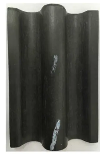
The preparation and performance tests of composite sinusoidal specimen were conducted in AVIC Beijing Institute of Aeronautical Materials. The composite sinusoidal specimen is 76.2 mm long, 50.80 mm wide from end-lip to end-lip, and 2 mm thick. The detailed dimensions is shown in Fig-ure1 (a), and the composite sinusoidal specimen is shown in FigFig-ure1 (b). The 45-degree chamfer sided weakness is set up at the top of the composite sinusoidal specimen in order to initiate steady crush. The material system is T700 carbon fiber/3234 epoxy prepreg, it is a unidirectional tape 12k tow, and a 270 ℉ (132 ℃) cure resin designated for autoclave or oven-only cure. The composite
sinusoidal specimen consists of 16 layers of unidirectional laminates with orientations [0°/90°]4s,
and each layer thickness is 0.125 mm. The uniform crushing rate is 2.5 mm/min, and the typical morphology of composite sinusoidal specimen after crush testing and the quasi-static crushing load-displacement curve are shown in Figure2 and Figure3, respectively.
(b) Composite sinusoidal specimen
Figure 1: Composite sinusoidal specimen.
Figure 2: Typical morphology of composite sinusoidal specimen after crush testing.
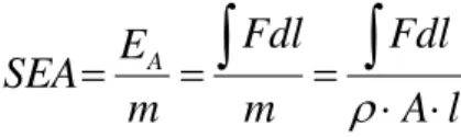
Specific Energy Absorption (SEA): The energy absorbed per unit mass of crushed structure. The ability of material to dissipate energy can be expressed in terms of SEA, which has units of J/g. Setting the mass of structure that undergoes crushing as the product of stroke l, cross-sectional area A, and density ρ:
l
A
Fdl
m
Fdl
m
E
SEA
A
(1)The calculating SEA value is 72.47 J/g for the composite sinusoidal specimen.
2.2 Finite Element Model
The LS-DYNA model is represented in Figure 4, and shows the rigid ground, the composite sinus-oidal specimen and the trigger row. The shell element is commonly used in crashworthiness simula-tion of aircraft fuselage secsimula-tion, and the fully integrated shell element (formulasimula-tion 16) is adopted for the finite element model of composite sinusoidal specimen because it can simulate bucking accu-rately, calculate internal energy absorption accuaccu-rately, and calculate vary fast (Paolo, 2011; LSTC, 2012). The finite element model of composite sinusoidal specimen is modeled with total of 840 shell elements of 2.54 mm×2.54 mm, having constant thickness of 2 mm. The 45-degree chamfer is
mod-eled as a single row of reduced thickness 0.25 mm elements at the crush front of the specimen.
Figure 4: Finite element model of rigid ground, composite sinusoidal specimen, and trigger row .
The card * PART_COMPOSITE is used to define the 16 layers of composite sinusoidal speci-men, and the finite element model is adopted the material model of MAT 54_Enhanced_Composite_Damage, which used the Chang-Chang failure criterion in the LS-DYNA theoretical manual (Han, 2007; LSTC, 2012). The material card of MAT 54 contains input parameters for both material physical properties of T700/3234 (Table 1) and other code-specific parameters (Table 2) ( Paolo, 2011; LSTC, 2012). The material physical properties of T700/3234
rigid ground
trigger row
are obtained from the material tests according to the CMH-17G (CMH-17 Working Group, 2012). The material model of MAT 20_Rigid is selected for rigid ground, and the input parameters of material card of MAT 20 are shown in Table 3 (LSTC, 2012).
Symbol Title Value
ρ Density 1.53 g/cm3
Ea Young’s modulus in longitudinal (fiber) direction 128 GPa
Eb Young’s modulus in transverse (perpendicular to fiber) direction 8.4 GPa
Gab Shear modulus in ab plane 4.0 GPa
Gbc Shear modulus in bc plane 4.0 GPa
Gca Shear modulus in ac plane 4.0 GPa
Prab Minor Poisson’s ratio 0.0218
Xt Longitudinal tensile strength (fiber direction) 2093 MPa
Xc Longitudinal compressive strength (fiber direction) 1060 MPa
Yt Transverse tensile strength (perpendicular to fiber) 50 MPa
Yc Transverse compressive strength (perpendicular to fiber) 198 MPa
Sc Shear strength in ab plane 104 MPa
Table 1: Material physical properties of T700/3234.
Symbol Title Value
DFAILT Max strain for fiber tension 0.0174 DFAILC Max strain for fiber compression -0.02
DFAIL
M Max strain for matrix straining in tension and compression 0.024
DFAILS Max shear strain 0.03
BETA Weighing factor for shear term in tensile fiber mode 0.5
FBRT Softening factor for fiber tensile strength after matrix failure 0.5 YCFAC Softening factor for fiber compressive strength after matrix failure 1.2
TFAIL Time step size criteria for element deletion 1.153e-9 SOFT Crush front strength reducing parameter 0.70
EFS Effective failure strain 0
Table 2: The other code-specific parameters of MAT 54.
Symbol Title Value
ρ Density 7.9 g/cm3
E Modulus of elasticity 210 GPa
μ Poisson's ratio 0.3
2.3 Material Damage Model
For the MAT54_Enhanced_Composite_Damage material model in LS-DYNA, the material stress-strain curves in the elastic region is as follows:
aa
=
1
a
E
(
aa-
v
ab
bb)
(2)bb
=
1
b
E
(
bb-
v
ba
aa)
(3)2
ab=
1
a b
G
ab+
3
a b
(4)
The Chang-Chang failure criterion is used to determine the behavior of MAT54 material (Chang, 1987; Han, 2007; Paolo, 2011; LSTC, 2012), if the material is beyond the elastic region, as follows:
(a) for the tensile fiber mode:
0
aa
,
2 20,
1
0,
aa ab f t cfailed
e
elastic
X
S
Ea=Eb=Gab=
ba=
ab=0(5)
(b)for the compressive fiber mode:
0
aa
,
2 20,
-1
0,
aa c cfailed
e
elastic
X
Ea=
ba=
ab=0(6)
(c) for the tensile matrix mode:
0
bb
,
2 20,
1
0,
bb ab m t cfailed
e
elastic
Y
S
Ea=
ba=0→
Gab=0(7)
(d)for the tensile fiber mode:
0
bb
,
2 2 20,
1
1
0,
2
2
bb c bb ab d
c c c c
failed
Y
e
elastic
S
S
Y
S
Ea=
ba=
ab =0→
Gab=02.4 Simulation and Validation of Finite Element Model
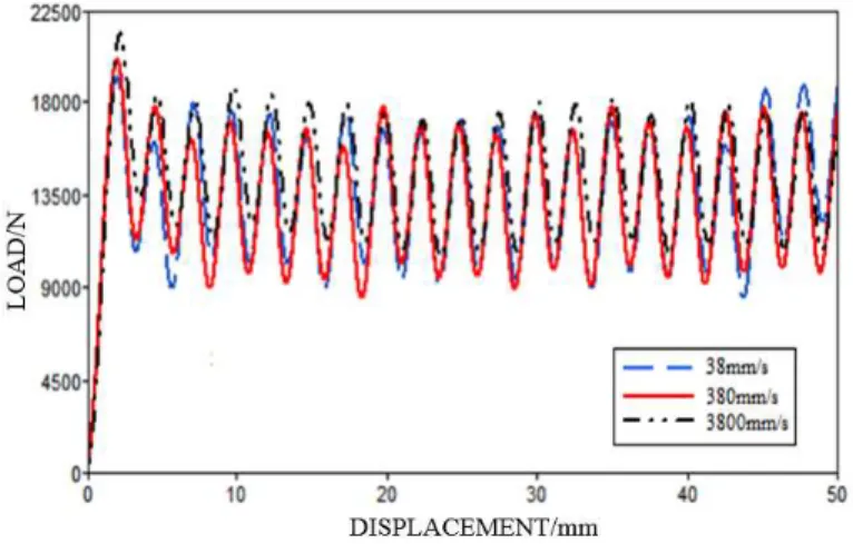
For the finite element model of composite sinusoidal specimen, the specimen is kept at rest by con-straining all freedom degrees of the bottom row of nodes opposite the crush trigger, and the top nodes of the crush trigger are completely free. The different loading speeds of rigid ground are 38 mm/s, 380 mm/s and 3800 mm/s, respectively. The simulation load-displacement curves are shown in Figure 5.
Figure 5: Load-displacement curves under different velocities.
As can be seen from Figure 5, there are little effects on peak loads, average crush loads, overall load-displacement responses and the absorbed energy regardless of the strain rate effects for differ-ent loading speeds. Solution time takes 4 minutes using a workstation with a 2.26 GHz dual Quad-core (8 processors) 64-bit 16 GB RAM computer when the loading speed of rigid ground is 3800 mm/s. The different solution times are listed in Table 4, the computational efficiency is significantly improved with the increasing of the loading speeds. Through a sensitivity study, the loading speed of 3800 mm/s is reasonable.
Loading speed/mm·s
-1 Solution time/min
3800 4
380 44
38 428
Table 4: Solution time under different loading speeds.
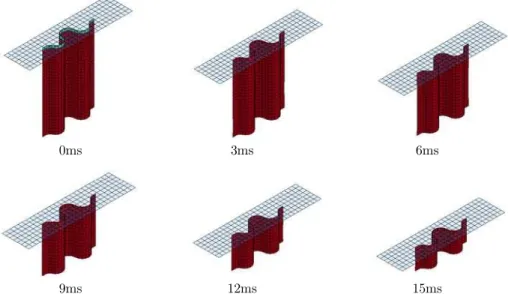
plies fail, the elements are immediately deleted. Once an element is deleted, the entire row of ele-ments is also deleted. Therefore, the crush progresses with a progressive deletion of the crush front row of elements are achieved without any other graphic indication.
0ms 3ms 6ms
9ms 12ms 15ms
Figure 6: Time progression of the baseline simulation showing stable element row deletion.
Figure 7: Experimental and model baseline load-displacement curves.
features, and the simulation SEA value is highly agreed with the experimental value, which can vali-date the correctness of finite element model, so the material model MAT 54 can also be used to suc-cessfully simulate the behavior of composite sinusoidal specimens undergoing axial crushing. Therefore, the composite sinusoidal specimens are used as sub-floor energy-absorbing structures of fuselage sec-tion, and the crashworthiness simulation analysis of fuselage section are further conducted based on the finite element model of composite sinusoidal specimen.
3 FINITE ELEMENT MODEL OF FUSELAGE SECTION
The finite element model of fuselage section with sub-floor composite sinusoidal specimens was built by using the computer software code HyperMesh (Han, 2007; Zou, 2012; Altair Engineering, 2013; Feng, 2013; Siromani, 2013), due to the aircrafts deformation mainly occured in fuselage sub-floor structure during a crash. The finite element model of fuselage section consisted of skin, fuselage frames, long stringers, oblique struts, floor beams, floor composite sinusoidal specimen, and so on. The length of finite element model of fuselage section was 1200 mm, and the radius of cargo com-partment was 1600 mm. The fuselage frames were redesigned, and the chosen design for fuselage section was represente on Figure 8, the composite sinusoidal specimens were horizontal arrangement among the frames and skin.
Because of large size and complexity of real fuselage section structures, the finite element model was reasonably simplified during the modeling process of fuselage section based on the simplified principles described by Adam (2003) and Ikuo (2000), the rivets, screws, windows, doors and cargo were ignored. The masses of seats and dummies were accounted as concentrated masses located at the junctions between seats and floor, as shown in Figure 8, the concentrated mass of each seat and dummy was defined to 88 kg according to Federal Aviation Regulation 25.562(b). The material model of rigid ground was selected to MAT 20_Rigid. The overall finite element model of fuselage section consisted of 184944 nodes and 180965 elements. The Belytschko-Tsay shell element had been adopted because the shell element could accurately and effectively simulate buckling and cal-culate internal energy absorption.
Left outside Left inside Right inside Right outside
skin
stringers
sinusoidal specimes
frames
cargo floor
rigid ground oblique structs
floor beams
In addition to composite sinusoidal specimens, the rest structures of fuselage section were made of aluminum alloy. Al 2024 was used for cargo floor and skin. Al 7075 was used for frames, stringers, seat tracks, floor beams and oblique struts. Aluminum alloy adopted the MAT 24 material model with the bilinear elastic–plastic properties, and the mechanical properties was shown in Table 5 (LSTC, 2012; Zou, 2012). The explicit dynamics finite element algorithm was used for the MAT 24 material model. The Belytschko-Tsay shell element would be failed if the effective strain reached the maximum plastic strain, and the yielding model of shells were the Von-Mises stress model. The vertical crash direction of finite element model was parallel to the normal direction of rigid wall, and the vertical impact velocity of 7 m/s was selected to evaluate the crashworthiness of fuselage section without considering aerodynamic force. Based on the penalty algorithm, Automat-ic_Single_Surface_Contact was used to define the contact relationships among skin, fuselage frames and rigid ground.
Material Density/ kg·m-3
Modulus of elasticity/
GPa
Poisson’s ratio
Yield modulus/
MPa
Enhanced modulus/ MPa
Maximum strain failure
criteria
Al 2024 2796 71 0.33 469 852 0.08
Al 7075 2768 71 0.35 269 908 0.15
Table 5: The aluminum mechanical properties.
4 CRASHWORTHINESS SIMULATION ANALYSIS OF FUSELAGE SECTION
4.1 Failure Modes
(a) 20ms (a) 20ms
(b) 40ms (b) 40ms
(c) 120ms (c) 120ms
Figure 9: The stress cloud of composite fuselage section at different times.
Figure 10: The deformation contour of composite fuselage section at different times.
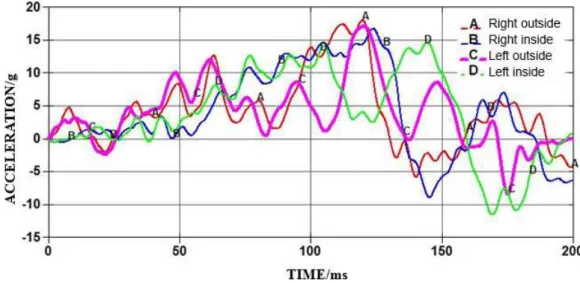
4.2 Acceleration Response Characteristics
Figure 11: Acceleration responses of the junctions between seats and floor.
Left
out-side Left inside Right inside Right outside
Positive peak acceleration corresponding time
17 g 120 ms
15 g 145 ms
16.5 g 130 ms
18 g 120 ms
Negative peak acceleration corresponding time
-8 g 175 ms
-11.5 g 170 ms
-8.5 g 145 ms
-5.5 g 140 ms
Table 6: Maximum peak acceleration and corresponding time.
Direction of accelerative force Occupant’s inertial response Tolerance level
Headward Eyeballs down 25 g
Tailward Eyeballs up -15 g
Table 7: Human tolerance limits to acceleration (JSSG-2010-7, 1998).
5 INFLUENCE OF DIFFERENT THICKNESS OF COMPOSITE SINUSOIDAL SPECIMENS ON
CRASHWORTHINESS OF FUSELAGE SECTION
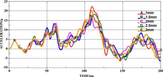
It is clear that the stiffness and stress of sub-floor composite sinusoidal specimens has a great effect on acceleration response characteristics of the fuselage section, though the sub-floor composite si-nusoidal specimens are not the main energy-absorbing component. The simulated acceleration vari-ation of fuselage section with different thickness of sub-floor composite sinusoidal specimens is plot-ted in Figure 12, and the thickness of sub-floor composite sinusoidal specimens is varied as 1 mm, 1.5 mm, 2.0 mm, 2.5 mm, and 3 mm, respectively.
0 50 100 150 200 TIME/ms
25
20
15
10
5
0
-5
-10
AC
CEL
E
R
A
T
IO
N
/g
Figure 12: Acceleration responses of different thickness of sub-floor composite sinusoidal specimens.
17.6 g. Therefore, the thickness of sub-floor composite sinusoidal specimens can limit the magnitude of peak acceleration.
Figure 13: Maximum peak acceleration with different thickness of sub-floor composite sinusoidal specimens.
6 CONCLUSIONS
The failure behaviors of composite sinusoidal specimens are researched based on the combination of methods of test and simulation, and the crashworthiness of fuselage section with composite sinusoi-dal specimens under cargo floor are further studied based on the composite material model and finite element model. The main conclusions are listed as follows:
(1) The mechanical properties parameters of T700/3234 are obtained by the performance tests, the energy-absorbing results of composite sinusoidal specimens are achieved by the crushing tests. The single-layer finite element model of composite sinusoidal specimen can accurately simulate the initial peak load, load-displacement curve and the SEA value, but the single-layer approach can provide no insight into the failure process.
(2) The composite sinusoidal specimens are used as sub-floor energy-absorbing structures of fuselage section. The failure process of fuselage section is more stable because of the pro-gressive failure of composite sinusoidal specimen, and the cabin floor is not penetrated by oblique struts.
(3) The acceleration is smaller in the earlier crash process because of the progressive failure of composite sinusoidal specimens. The acceleration is gradually increased in the later crash process because the oblique struts are in contact with rigid ground. However, the maxi-mum positive peak acceleration does not exceed 25 g, and the maximaxi-mum negative peak acceleration does not exceed -15 g, which can ensure the safety of occupants.
increases. A critical thickness of sub-floor composite sinusoidal specimens can restrict the magnitude of peak acceleration of fuselage section, which can greatly improve the surviv-ability of passengers.
Acknowledgement
The authors acknowledge the supports from Science and Technology Item from Civil Aviation Administration of China (MHRD20140207), Fundamental Research Funds for the Central Universities (3122015D022), and Fund of Tianjin Key Laboratory of Civil Aircraft Airworthiness and Maintenance in Civil Aviation University of China.
References
Abramowitz, A., Smith, T. G., Vu, T., Zvanya, J., (2002). Vertical drop test of a narrow-body transport fuselage section with overhead stowage bins, Report Number DOT/FAA/AR-01/100.
Adams, A., Lankarani, H. M., (2003). A modern aerospace modeling approach for evaluation of aircraft fuselage crashworthiness. International Journal of Crashworthiness 8(4): 401-413.
Altair Engineering, (2014). Hypermesh user’s guide. Altair Engineering Inc.
Chang, F. K., Chang, K. Y., (1987). A progressive damage model for laminated composites containing stress concen-tration. Journal of Composite materials (21): 834-855.
CMH-17 Working Group, (2012). Composite Materials Handbook (CMH-17G), Volume 1 Guidelines for characteri-zation of structural material, Release G.
Damodar, R. A., Marshall, R., (2005). Design and evaluation of composite fuselage panels subjected to combined loading conditions. Journal of Aircraft 42(4):1037-1045.
David, D., Didier, J., Michel, M., Gérard, W., (2004) Evaluation of finite element modeling methodologies for the design of crashworthy composite commercial aircraft fuselage. 24th International Congress of the Aeronautical Sci-ences. Department of defense joint service specification guide. (1998). JSSG-2010-7 crew systems crash protection handbook.
Deleo, F., Wade, B., Feraboli, P., Rassaian, M., (2009). Crashworthiness of Composite Structures: Experiment and Simulation. Proceedings of the 50th AIAA Structures, Structural Dynamics and Materials Conference, Palm Springs, CA, May 4-7.
Feng, Z. Y., Mou, H. L., Zou, T. C., Ren, J., (2013). Research on effects of composite skin on crashworthiness of composite fuselage section. International Journal of Crashworthiness 18(5): 459-464.
Feraboli, P., (2008). Development of a corrugated test specimen for composite materials energy absorption. Journal of Composite Materials 42(3): 229-256.
Feraboli, P., Rassaian, M., (2010). Proceedings of the CMH-17 (MIL-HDBK-17) Crashworthiness Working Group Numerical Round Robin. Costa Mesa, CA.
Feraboli, P., Wade, B., Deleo, F., Rassaian, M., Higgins, M., Byar, A., (2011). LS-DYNA mat54 modeling of the axial crushing of a composite tape sinusoidal specimen. Composites: Part A 42: 1809-1825.
Han, H. P., Taheri, F., Pegg, N., Lu, Y., (2007). A numerical study on the axial crushing response of hybrid pultrud-ed and ±45° braided tubes. Composite Structures (80): 253-264.
Heimbs, S., Hoffmann, M., Waimer, M., Schmeer, S., Blaurock, J., (2013). Dynamic testing and modelling of compo-site fuselage frames and fasteners for aircraft crash simulations. International Journal of Crashworthiness 18(4): 406-422.
Ikuo, K., Masakatsu, M., Kazuo, I., (2000). Impact simulation of simplified structural models of aircraft fuselage. San Diego: 2000 World Aviation Conference 1-6.
Ilcewicz, L. B., Brian, M., (2005). Safety & certification initiatives for composite airframe structure. 46th AI-AA/ASME/ ASCE/AHS/ASC structures, Structural Dynamics & Materials Conference, Austin, Texas.
Jackson, K. E., Fasanella, E. L., (2001). Development of a scale model composite fuselage concept for improved crashworthiness. Journal of Aircraft 38(1): 95-103.
Jackson, K. E., Fasanella, E. L., (2002). Crash simulation of vertical drop tests of two Boeing 737 fuselage sections, Report Number DOT/FAA/AR-02/62.
Jackson, K. E., Fasanella, E. L., (2008). Development and validation of a finite element simulation of a vertical drop test of an ATR 42 regional transport airplane, Report Number DOT/FAA/AR-08/19.
LSTC., (2012). LS-DYNA theoretical manual. California: Livermore Software Technology Corporation.
Mamalis, A. G., Manolakos, D. E., Ioannidis, M. B., Papapostolou, D. P., (2006). The static and dynamic axial collapse of CFRP square composite tubes: Finite element modeling. Journal of Composite Structures 74: 213-225. Palanivelu, S., Paepegem, W., Degrieck, J., Kakogiannis, D., Ackeren, J., Hemelrijck, D., (2010). Parametric study of crushing parameters and failure patterns of pultruded composite tubes using cohesive elements and seam, Part I: Central delamination and triggering modeling. Polymer Testing 29: 729-741.
Paolo, F., Bonnie, W., Francesco, D., Mostafa, R., Mark, H., Alan, B., (2011). LS-DYNA MAT54 modeling of the axial crushing of a composite tape sinusoidal specimen. Composite: Part A 42: 1809-1825.
Siromani, D., (2013) Crashworthiness design and analysis of aircraft structures. Drexel University, Doctor of Philos-ophy 1-245. Terry, J. E., Hooper, S. J., Nicholson, M., (1997). Design and test of an improved crashworthiness small composite airframe–phase II report, NASA SBIR Contract NAS1-20427, Terry Engineering, Andover, Kansas. Terry, J. E., (2000) Design and test of an improved crashworthiness small composite airplane, SAE Paper 2000-01-1673, Presented at the SAE General Aviation Technology Conference and Exposition, Wichita, KS.
Waimer, M., Kohlgruber, D., Hachenberg, D., Voggenreiter, H., (2013). Experimental study of CFRP components subjected to dynamic crash loads. Composite Structures 105: 288-299.
Wiggenraad, J. F. M., Michielsen, A. L. P. J., Santoro, D., Lepage, F., Kindervater, C., Beltran, F., (1999). Devel-opment of a crashworthy composite fuselage structure for a commuter aircraft, NLR-TP-99532.
Wiggenraad, J. F. M., Santoro, D., Lepage, F., Kindervater, C., Mañez, H. C., (2001). Development of a crashworthy composite fuselage concept for a commuter aircraft, NLR-TP-2001-108.
Xiao, X., (2009). Modeling energy absorption with a damage mechanics based composite material model. Journal of Composite Materials 43(5): 427-444.
Xiao, X., Botkin, M., Johnson, N. L., (2009). Axial crush simulations of braided carbon tubes using MAT58 in LS-DYNA. Thin-Walled Structures 38: 2247-2259.
Xue, P., Ding, M. L., Qiao, C. F., Xu, T. X., (2014). Crashworthiness study of a civil aircraft fuselage section. Latin American Journal of Solids and Structures 11(9):1615-1627.