Assessment of Process Parameters by Friction Surfacing on the Double Layer Deposition
Juan Carlos Galvisa* , Pedro Henrique Fernandes Oliveiraa , Juliana de Paula Martinsb, André Luis Moreira de Carvalhoa
Received: January 17, 2018; Accepted: February 19, 2018
The friction surfacing process of two deposited layers on two deposition surface conditions, i.e., a smooth interface and a rough interface, was investigated. The control parameter of the deposition process was the rod feed rate with the use of a conventional milling machine. Analyzes of the surface characterization and microstructural characterization along the produced deposits were performed. The interface strength of the substrate/deposit1 (smooth) and deposit1/deposit2 (rough) was evaluated by bending tests and the micro-hardness profile along the transverse section of the substrate/deposit1 and deposit1/deposit2. The bending tests revealed the presence of smalls delaminations with no evidence of fracture at the rough deposit1/deposit2 interface (D1/D2) with less predominance in the deposition condition 3B. This suggests that the combination of the travel speed of 5.5 mm/s and an increase in the consumable rod feed rate of (≥5.5 mm/s) increases the adhesive strength of the two produced interfaces.
Keywords: Friction surfacing, Process parameters, Double Layer, Deposition roughness, Mechanical anchorage, Conventional milling machine.
*e-mail address: [email protected]
1. Introduction
The continuous development of new technologies and techniques that allow metallic materials to be joined, deposition of material for fabrication of profiles, superficial coating and component recovery, with their characteristics preserved, has been generating great interest in the industrial area in recent years. The search for new alternatives encourages the implementation and incorporation of viable, low cost and reproducible options. The friction surfacing, within these options, is a deposition process that represents an alternative technique for joining and surface coating of similar and/or dissimilar metal components. The process uses heat as the driving force to promote the plastic deformation of a consumable rod on the substrate. Initially, the rod is subjected to a rotational movement with the application of an axial load on the substrate. The heat generated in the friction results in the softening and plastic deformation of the material at the tip of the consumable rod. After plastification occurs, the substrate is subjected to a relative longitudinal movement (advancing) causing the deposition of a layer of the consumable on the substrate. Figure. 1 schematically shows the deposition system and the main process parameters.
Friction Surfacing is a process involving adhesion mechanisms through diffusion that presents great advantages when compared to conventional joining processes (fusion)1. One of the great challenges the Friction Surfacing is to
improve the degree of adhesion at the edges of the deposits produced in the processing that influences the adhesion quality of the finished products. Therefore, the control of this defect known as cold weld line (undercut) has been studied from the deposition of several deposited layers2.
aDepartamento de Engenharia de Materiais, Universidade Estadual de Ponta Grossa - UEPG, Av.
Carlos Cavalcanti, 4748, 84030-900, Ponta Grossa, PR, Brasil
bDepartamento de Engenharia Química, Universidade Tecnológica Federal do Paraná, Av Monteiro
Lobato, s/n, km 04, 84016-210, Ponta Grossa, PR, Brasil
Tokisue et al.3 studied the deposition of AA2017 aluminum alloy rods on AA5052 aluminum alloy sheets with double depositions. The process consisted in conducting the second deposition by moving the substrate table at 0, 5, 10 and 15 mm parallel to the first layer deposited on the advancing or indenting sides respectively. The results showed that the deposition of the second layer allowed the decrease
of unbound edges (cold weld) of the first deposited layer. However, there was no clear effect of the influence of the displacements used in the double deposition on the mechanical properties analyzed in this article. Lambrineas and Jewsbury4 investigated different configurations of multiple deposited layers in order to cover surfaces for applications in the maritime industry. The superposition of the deposits was not enough to fully consolidate the joint of the unbound edges of the deposits leaving them empty at the interface between the deposits. Batchelor et al.5 studied the deposition of several layers of stainless steel, producing three depositions firmly connected to each other. The depositions were conducted with maintenance of the natural roughness of the deposits. Gandra et al.6 developed a study of the wear resistance in an approach based on the deposition of multiple layers by friction surfacing.
It is important to note that even when the cold weld line region decreases with the deposition of several layers, joining the material at the edges cannot be fully consolidated. Consequently, further machining processes to improve the finish and eliminate these defects are necessary. Puli and Janaki Ram7 proposed to machine the unbonded edges by up to 3 mm (1.5 mm each side) before performing the next deposition. In addition, the deposition of multiple successive layers increases the thickness of the coating surface, thus increasing the possibility of producing profiles with desired geometries after machining processes8.
Although studies have been conducted to improve the quality of joining coatings and the reduction of the cold weld regions, few studies have investigated the influence of multilayer deposition on the quality of the joining deposits on the substrate, where the roughness characteristic of the substrates after processing has been maintained between each deposit.
In this context, this article studies two types of interfaces produced in the deposition of two deposited layers with characteristics of smooth and rough joining. That is, in the deposition of the first layer on the substrate, the surface of the substrate is smooth, while in the deposition of the second layer the deposition surface was produced while maintaining the natural roughness of the first layer as a substrate. The main highlight of this article is the emphasis on the deposition characteristics obtained along the rough interface, generated between the two deposited layers, due to the research's process control parameters. Consequently, the aim is to evaluate the microstructure of the deposited material along the two interfaces generated from a microstructural characterization. And, additionally, to evaluate the mechanical behavior of the deposits around the two interfaces through bending tests and hardness profiles. The process was developed using a conventional milling machine where the deposition control was performed by the consumable rod feed rate. The article could contribute in the use of conventional tools, as a viable option for the development of the process, and the advantages that could generate in the industry.
2. Experimental Details
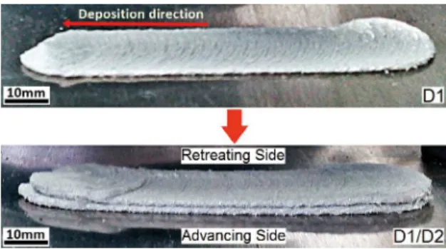
The friction surfacing process was performed with 6351 aluminum alloy consumable rods in condition T6 (nominal composition (wt.%): 98.1Al-0.41Mg-0.86Si-0.42Mn-0.072Cu-0.19Fe-0.003Cr) with 19.05 mm in diameter. Meanwhile, 5052-H32 aluminum alloy sheets (nominal composition (wt.%): 97.5Al-1.87Mg-0.086Si-0.006Mn-0.009Cu-0.27Fe-0.21Cr) of 2.56 mm thickness were used as substrate. The process parameters were: the travel speed (VA), the rotation speed (VR) which was kept constant for each deposition in a value of 3000 rpm. The control parameter used in the processing was the consumable rod feed rate (Vz), which is calculated for each deposit as a function of the upward axial displacement of the table (DZ) and the total deposition time (t). The axial force acting on the process is a result of the movement of the table in the upward direction. The deposition rate (DR) and deposition efficiency (Ef) as the process data depending on the rod feed rate were calculated to address the efficiency of the chosen parameters. The control and deposition parameters used in FS processing can be seen in Table 1. The equipment used in the processing of the consumable material was a KONE KFE-3/BR conventional milling machine equipped with position control in the three axes of the table and fixed head with rotation capacity of 4200 rpm. Double layer deposition (one above the other) was performed. As the main highlight of this study, the second layer was deposited on the first layer maintaining the natural roughness resulting from the first deposition, as shown in Figure. 2. The investigative character in this phase was to evaluate the adhesion characteristics of the two layers on the substrate and, mainly, to analyze the effect of the roughness of the first layer on the adhesion of the second deposited layer using as process control the feeding rate of the consumable rod (VZ).
Table 1. Process parameters and control of friction surfacing
Experiment
Control and deposition parameters used in FS VAa
(mm/s)
VRa (rpm)
(DZb ± 0.05) mm
(tb ± 0.2) s
(VZc ± 0.1) mm/s
(DRc ± 0.05) cm3/min
1B - 1B’ 4
3000
61.30 12.87 4.8 90.25
2B - 2B’ 5 64.14 12.05 5.3 91.44
3B - 3B’ 5.7 63.04 11.45 5.5 95.76
a Programed; b Measured; c Calculated
Figure 2. Double-layer deposition sequence maintaining the
roughness of the first deposited layer
were performed according to ASTM E-290 in a Shimadzu AG-10 mechanical test machine with a capacity of 10 kN and applied load at 5 mm/min.
3. Results and Discussion
3.1 Surface characterization of deposits
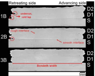
Figure 4 shows the transversal macrographs of samples drawn at the center of each of the deposits made under conditions 1B, 2B and 3B, respectively. It is possible to identify a straight line at the substrate/deposit1 interface, which divides the substrate of the deposit (S/D1); whereas in the rough deposit1/deposit2 interface (D1/D2) the two surfaces joined without evidence of the interface. As described above, and contrary to the procedure developed by Dilip and Janaki Ram9, the deposition of the second layer was performed maintaining the roughness resulting from the first layer. Thus,
Figure 3. Deposits produced for each deposition condition and its corresponding duplicate
double-layer deposits with average thickness of 4.38, 4.30 and 4.33 mm (±0.05) were obtained. According to Vitanov, Voutchkov and Bedford10, the friction surfacing process has a specific feature at the edges of the deposits, known as undercut. This characteristic is influenced by the deposition control of the process, due to the axial force applied or by the consumable rod feed rate. Consequently, the deposition control determines the material flow during the process both in the rotation level (contact between the consumable rod and the top of the deposit) and in the translation level (contact between the substrate and the bottom of the deposit)11,12. In this article, from Figure 4, in the deposition process 3B controlled by the consumable rod feed rate of 5.5 mm/s (Table 1), there was a significant decrease in the occurrence of undercut at the edges of the deposits, when compared to depositions 1B and 2B. Consequently, this decrease results in increasing the effective width of the two layers deposited on the substrate, as discussed in Figure 5. On the other hand, in Figure 4, the maintained surface roughness of the first deposited layer does not contribute to the decrease of cold welding defects (undercut).
Figure 4. Transversal macrographs of the deposits produced with VA = 4, 5, 5.7 mm/s; VZ = 4.8, 5.3, 5.5 mm/s and VR=3000 rpm
(deposit conditions 1B, 2B, 3B)
Figure 5. Effect of consumable rod feed rate on: a) Length, b) Width,
Effective width and c) Thickness of deposits produced with VA = 4,
5, 5.7 mm/s; VZ = 4.8, 5.3, 5.5 mm/s and VR=3000 rpm (deposition conditions 1B, 2B, 3B)
of 5.7 mm/s as shown in Figure 5b. However, the effective width, understood as the region of the deposit that is adhered to the substrate (Figure 4)13, reveals a gradual increase with increasing consumable rod feed rate (Figure 5b). It is important to clarify that the deposition of consumable rods was performed with three different consumable rod feed rate values (Table 1). As emphasized above, the increase in the consumable rod feed rate VZ and the travel speed VA results in the increase of the effective width and a decrease of the undercut, as previously described (Figure 4). Normally, when the deposition process is controlled by the applied
axial load, the effective width is smaller than the consumable rod diameter (<3 mm), as reported by Nicholas (1993) and Voutchkov et al.1,14. In this article, the deposition process, controlled by the consumable rod feed rate, produced in the smooth interface substrate/deposit1 (S/D1) a 3.5% increase in the effective width value when compared to the rod used in the processing of the consumable material (19.05 mm).
On the other hand, in Figure 5c, there is a slight decrease in deposit thickness values with increasing consumable rod feed rate. This behavior may be associated with the increase in the consumable rod feed rate control used to produce the deposits in the 3B deposition condition, which was approximately 14.8% higher when compared to condition 1B (Table 1). It is important to emphasize that the increase in rod feed rate induces an increase in the load/pressure acting on the system, resulting in the production of deposits with smaller thickness as reported by Gandra et al.2.
3.2 Consumable rod feed rate
The consumable rod feed rate, as the control parameter used in the deposition process, is determined by the ratio between the axial displacement of the machine table (DZ) over the total deposition time t. It represents the speed at which the rod is consumed along the upward axial displacement of the table relative to the substrate in the friction surfacingprocess. Consequently, the axial load acting on the process is a result of the deposition control used.
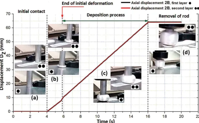
Figure 6 shows the evolution of the consumable rods feed rate used to produce the two deposits with deposition condition 2B. In the deposition order, the deposit 1 (black profile) is recorded from the initial rotation of the rod, followed by the contact of the substrate on the consumable (●) and after the deposition. Similarly, deposit 2 (red profile) is recorded from the initial rotation of the rod, followed by contact of the first layer deposited on the consumable (●●) and after the deposition. The total conclusion of the deposition process for each case lasted an approximate time of 20 s.
Figure 6. Evaluation of rod feed rate with time in the deposition of double layer AA6351-T6 over AA5052-H32. Initial deformation was
controlled by consumable rod feed rate at 4.7 mm/s. a) Initial contact; b) end of initial deformation; c) deposition process; d) removal of
consumable rod. Process parameters for 2B condition: VZ = 5.3 mm/s; VA = 5 mm/s; VR = 3000 rpm
3.3 Rate and efficiency of deposition
The deposition rate (DR), defined as the amount of deposited material per unit time, was calculated from the product between the rod feed rate (VZ) and the transversal area of the two layers deposited on the substrate16. Figure 7a shows the variation of the deposition rate as a function of the rod feed rate used to produce the corresponding deposits under conditions 1B, 2B and 3B, respectively. In Figure 7a, the increase of the rod feed rate results in an increase of the deposition rate (DR) of approximately 5.8% in the deposition condition 3B, as compared to the condition 1B. Accordingly, increasing travel speed (VA) and the consumable rod feed rate (VZ) promotes a decrease in the thickness of the deposit as described in Figure 5c, however, an increase in the effective width of the deposit. Similar results were reported by Gandra et al.13. On the other hand, Figure 7b shows the variation of the deposition efficiency with the rod feed rate of each of the deposits performed. The deposition efficiency (Ef) represents the relationship between the deposited volume and the consumed volume of the rod17. In this case of double layer deposition, the deposited volume is calculated from the product between the effective width Ae of the smooth interface, the thickness Ap composed of the two deposited layers and the travel speed (VA) used in each deposition condition, whereas the consumed volume of the rod represents the product between the rod feed rate (VZ) and the consumable (constant) transversal area. As previously
described in Figure 5b, increasing the travel speed results in increasing the effective width of the deposits. In turn, the increase of the consumable rod feed rate contributes in decreasing the thickness of the produced deposits. Thus, the effect of these variations between the three conditions analyzed promotes, in the deposition efficiency Ef , a 10% increase with regard to the difference between the efficiency values of conditions 1B and 3B, respectively, as shown in Figure 7b.
3.4 Microstructural analysis
Figure 8 shows the microstructure of the consumable material (AA6351-T6) prior to processing. A morphology of equiaxed grains in the transversal direction DT can be observed in the extrusion process (Figure 8a). Whereas an anisotropic grain structure aligned along the direction of extrusion of the rod is shown in Figure 8b.
Figure 7. Influence of travel speed on: a) deposition rate DR; b) deposition efficiency Ef
Figure 8. As-received AA6351-T6 consumable rod microstructure: a) perpendicular to rod extrusion direction; b) parallel to rod extrusion direction
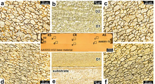
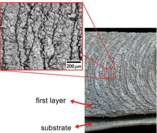
Figure 9b shows the microstructure of the two deposits along the interface region D1/D2. In this case, the authors noticed a homogeneous section formed by the two layers deposited without evidence of a region that enables the identification of a deposit of the other one, whereas in the substrate/D1 interface region, the presence of a line dividing the two surfaces is shown in Figure 9e.
The micrographs of Figure 10a-c show the microstructure of each deposition condition throughout the deposit1/deposit2 interface region. In micrographs it is possible to observe the presence of a discontinuous line between the deposit interface (D1/D2). As reported by Nicholas and Thomas20, in the friction surfacing process the heat generated by the friction between the two surfaces in contact with each other reaches temperatures below the melting temperature of the
materials, thus indicating that joining thereof involves diffusion mechanisms. In this article, the interface D1/D2 (Figure 10) also reveals the mechanism of mechanical anchoring, which can be attributed to the roughness of the first layer and favoring joining the materials, as reported by Weiss21. On the other hand, this was contrary to what was shown by Dilip and Janaki Ram9. It is important to emphasize that the double deposition process was conducted continuously (one after the other), avoiding the presence of impure particles and the formation of oxides on the roughness of the first layer as shown in Figure 11.
3.5 Vickers Micro-hardness
Figure 9. Transversal section with a cut in the center of a double-layer deposit in the deposition condition 2B revealing the microstructure in regions of: a) Retreating side in deposit D2, b) Interface D1/D2, c) Advancing side in deposit D2, d) Retreating side in deposit D1, e) Substrate/deposit interface D2, and f) Advancing side in deposit D1
Figure 11. Macrography of the surface roughness of the first layer.
Free section of impurities and oxides before deposition process of the second layer
obtained in the three deposition conditions indicated in Table 1. In Figure 12, the hardness values in the substrate decrease to 20%, 16% and 10.4% (2B, 3B and 1B respectively) when compared to the hardness values of the substrate (plate AA5052-H32) before processing. This decrease in the hardness values may be associated to the temperature gradient experienced in the substrate during the friction with the consumable rod, whenever the heat-affected zone (HAZ) produced in the substrate is concentrated in the central region, as expected.
Figure 12. Hardness profile measured along the central region CR of each of the deposits obtained under the used deposition conditions
Moreover, loss of the T6 condition, along the D1/D2 deposits was around 25.4%, when compared to the hardness of the consumable rod as received. In the deposition region D1/D2, the hardness values show a similar behavior, for the three travel speed conditions used in this study. This result is contrary to the result reported by Gandra et al.6. In addition, it is possible to observe in Figure 12 the hardness values along the thickness of the two deposits specifically in the vicinity of interface D1/D2 are similar, indicating that the heat flow produced between the deposited layers (D1/ D2) did not influence the decrease in hardness values. Also hardness values from the transversal section of the double layer measured at the advancing and retreating sides are reported in Table 2. The hardness values are close to the mean values measured at the center of each deposit as expected.
3.6 Bending test
Table 2. Average hardness values in double-layer transversal section D1/D2 measured on the retreating side RS, center region CR and advancing side AS of the three deposition conditions.
Deposit condition (Experiment)
Microhardness (HV0,2) in cross section D1/D2
Retreating Side RS Center Region CR Advancing Side AS
1B 62.73 63.51 62.74
2B 60.56 61.14 60.16
3B 61.86 62.56 61.21
Uncertainty value±0.05
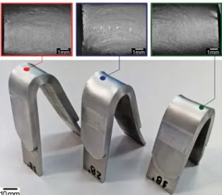
Figure 14. Surface bending section in test specimens without evidence of fracture after testing
presence on both the retreating side and the advancing side along the two interfaces is revealed, Figure 13 c,f. These results show that the higher the consumable rod feed rate of the consumable rod, the greater the axial load applied. Consequently, the proportional increase of the rod feed rate provides more favorable strength/pressure conditions to obtain better adhesion between the two interfaces (S/D1 and D1/D2). It is important to emphasize that in the friction surfacing process, the consumable rod feed rate and applied load are always correlated with each other as reported by Vitanov et al.10. Also in Figure 13a-f, with the increasing consumable rod feed rate, the occurrence of delamination along the D1/D2 interface decreases. Similarly, it is possible to note the absence of fracture along the upper bending section as shown in Figure 14.
4. Conclusions
This article evaluated the effect of the roughness of the first deposited layer on adhesion of the second layer using three different rates of consumable rod feed, such as process control. All the surface depositions were conducted through a conventional milling machine, the main results can be thus shown:
• The microstructure of the processed material (AA6351-T6) showed a fine grained morphology on the retreating (RS) and advancing (AS) sides indicating few variations of grain size between deposited layers.
• The consumable rod feed rate of 5.5 mm/s significantly decreases the occurrence of undercut at the edges of the deposits, when compared to the other two rod feed rates. In addition, the bonded width of the deposit increases with the increase of the consumable rod feed rate.
• In the interface region D1/D2, the hardness values show a similar behavior for the three investigated conditions. Consequently, the hardness values along the deposits D1/D2 results in the reduction of hardness of 25.4% when compared to the consumable rod. • The roughness of the first layer contributes to the mechanical anchoring mechanism occurring along interface D1/D2. However, the maintained surface roughness of the first deposited layer does not contribute to the decrease of cold welding defects (undercut).
• The bending tests revealed the presence of smalls delaminations with no evidence of fracture at the rough interface deposit1/deposit2 (D1/D2) with less predominance in the 3B deposition condition. This suggests that the combination of the travel speed of 5.7 mm/s, and an increase in the consumable rod feed rate (≥5.5 mm/s) increases the adhesive strength of the two smooth S/D1 and rough D1/D2 interfaces produced after processing.
5. Acknowledgments
The authors acknowledge Coordination for the Improvement of Higher Education Personnel (CAPES) for the financial support, to National Service for Industrial Training (SENAI) for the opportunity and facilities to use the conventional milling machine and UEPG -State University of Ponta Grossa for the opportunity and facilities from the Multiusers Laboratory Complex C-Labmu. The authors are also grateful the Consortium in R&D by Friction Processing (C2PA) of number VDT055-12.
6. References
1. Nicholas ED. Friction surfacing. In: Olson DL, Siewert TA, Liu S, Edwards GR, eds. ASM Handbook Volume 6: Welding Brazing and Soldering. Materials Park: ASM International;
1993. p. 321-323.
2. Gandra J, Krohn H, Miranda RM, Vilaça P, Quintino L, dos
Santos JF. Friction surfacing - A review. Journal of Materials Processing Technology. 2014;214(5):1062-1093. DOI: 10.1016/j. jmatprotec.2013.12.008
3. Tokisue H, Katoh K, Asahina T, Usiyama T. Mechanical Properties
of 5052-2017 Dissimilar Aluminum Alloys Deposit by Friction Surfacing. Materials Transactions. 2006;47(3):874-882. DOI: 10.2320/matertrans.47.874
4. Lambrineas P, Jewsbury P. Areal coverage using friction
surfacing. Journal of Ship Production. 1992;8(3):131-136.
5. Batchelor AW, Jana S, Koh CP, Tan CS. The effect of metal
6. Gandra J, Vigarinho P, Pereira D, Miranda RM, Velhinho A, Vilaça P. Wear characterization of functionally graded Al-SiC
composite coatings produced by Friction Surfacing. Materials & Design (1980-2015). 2013;52:373-383. DOI: 10.1016/j. matdes.2013.05.059
7. Puli R, Janaki Ram GD. Microstructures and properties of
friction surfaced coatings in AISI 440C martensitic stainless steel. Surface and Coatings Technology. 2012;207:310-318. DOI: 10.1016/j.surfcoat.2012.07.001
8. Vilaça P, Vidal C, Gandra J. Linear friction based processing
technologies for aluminum alloys: surfacing, stir welding and stir channeling. In: Ahmad Z, ed. Aluminium Alloys - New Trends in Fabrication and Applications. Rijeka: InTech; 2012. DOI: 10.5772/52026
9. Dilip JJS, Janaki Ram GD. Microstructure evolution in aluminum alloy AA 2014 during multi-layer friction deposition.
Materials Characterization. 2013;86:146-151. DOI: 10.1016/j. matchar.2013.10.009
10. Vitanov VI, Voutchkov II, Bedford GM. Decision support system to optimise the Frictec (friction surfacing) process. Journal of Materials Processing Technology. 2000;107(1-3):236-242. DOI: 10.1016/S0924-0136(00)00710-X
11. Fukakusa K. On the characteristics of the rotational contact plane - a fundamental study of friction surfacing. Welding International. 1996;10(7):524-529. DOI: 10.1080/09507119609549043
12. Rafi HK, Phanikumar G, Rao KP. Material Flow Visualization
during Friction Surfacing. Metallurgical and Materials Transactions A. 2011;42(4):937-939. DOI: 10.1007/s11661-011-0614-2
13. Gandra J, Pereira D, Miranda RM, Vilaça P. Influence of Process Parameters in the Friction Surfacing of AA 6082-T6 over AA
2024-T3. Procedia CIRP. 2013;7:341-346. DOI: 10.1016/j. procir.2013.05.058
14. Voutchkov I, Jaworski B, Vitanov VI, Bedford GM. An integrated approach to friction surfacing process optimisation. Surface and Coatings Technology. 2001;141(1):26-33. DOI: 10.1016/ S0257-8972(01)01127-6
15. Gandra J, Pereira D, Miranda RM, Silva RJC, Vilaça P. Deposition
of AA6082-T6 over AA2024-T3 by friction surfacing - Mechanical and wear characterization. Surface and Coatings Technology. 2013;223:32-40. DOI: 10.1016/j.surfcoat.2013.02.023
16. Galvis JC, Oliveira PHF, Hupalo MF, Martins JP, Carvalho ALM. Influence of friction surfacing process parameters to
deposit AA6351-T6 over AA5052-H32 using conventional milling machine. Journal of Materials Processing Technology. 2017;245:91-105. DOI: 10.1016/j.jmatprotec.2017.02.016
17. Gandra J, Miranda RM, Vilaça P. Performance analysis of
friction surfacing. Journal of Materials Processing Technology. 2012;212(8):1676-1686. DOI: 10.1016/j.jmatprotec.2012.03.013
18. Thomas WM, Nicholas ED, Needham JC, Searle JG. Friction surfacing. Google Patents; 1992.
19. Oliveira PHF, Galvis JC, Martins JP, Carvalho ALM. Application of Friction Surfacing to the Production of Aluminum Coatings
Reinforced with Al2O3 Particles. Materials Research. 2017. In press. DOI: 10.1590/1980-5373-MR-2017-0039
20. Nicholas ED, Thomas WM. A review of friction processes for
aerospace applications. International Journal of Materials and Product Technology. 1998;13(1-2):45-55. DOI: 10.1504/
IJMPT.1998.036227
21. Weiss H. Adhesion of advanced overlay coatings: mechanisms