Abstract
The phenomena of reflection and refraction of plane waves incident obliquely at a plane interface between uniform elastic solid half-space and porous solid containing liquid filled bound pores and two-phase fluid in connected pores has been analyzed. The amplitude ratios of the reflected and refracted waves to that of the incident wave are calculated as a non- singular system of linear algebraic equations. These amplitude ratios are used further to derive the expressions for the partition of incident energy among the reflected and refracted waves. Partition of incident energy among the reflected and refracted waves is studied for incidence of P and SV waves. The conservation of the energy across the interface is verified. The effect of gas saturation, wave frequency, capillary pressure and bound liquid film on the amplitude ratios and energy partitions are studied in the numerical example.
Keywords
Reflection; refraction; porous solid; amplitude ratios; frequency; capillary pressure; bound liquid film.
Reflection/refraction at the interface of an elastic solid and a
partially saturated porous solid containing liquid filled bound pores
and a connected pore space saturated by two-phase fluid
1 INTRODUCTION
A poroelastic solid is considered as an elastic matrix with a Newtonian fluid filling its connected pores. Dynamic behavior of fluids saturated porous media has been the center of study due to their importance in modelling the sedimentary materials in the field of acoustics, oil exploration, earthquake engineering, soil dynamics and hydrology. The dynamic equations formulated by Biot (1956a, b, 1962) are, generally, used to derive the mathematical models for wave propagation studies in a poroelastic solid saturated completely with a single-fluid phase. Pride et al. (2004) extended the Biot's single pore fluid formulation to the porous media saturated by multiple fluids.
Rajesh Saini
Department of Mathematics,
Kurukshetra University, Haryana, India-136119
Corresponding author: [email protected]
http://dx.doi.org/10.1590/1679-78251834
Mixture theory seems to be convenient in studying the wave propagation in a porous solid saturated by multiphase fluid. It was Brutsaert (1964), who predicted the existence of third compressional wave due to presence of second fluid in pores. In this, the constituent phases are assumed to exist everywhere, but without any integration between them. Bowen (1976, 1980) has given an extensive study of mixture theory. The work of Bedford and Drumheller (1983) deals with mixture of immiscible constituents. Garg and Nayfeh (1986) have studied the propagation of compressional waves in porous media saturated with chemically non-reactive miscible liquid/gas mixture. Santos et al. (1990a, b) derived the governing equations and presented a method to calculate elastic constants for isotropic porous solids saturated by two-phase fluids. Garg and Nayfeh (1986), and Tuncay and Corapcioglu (1997) formulated a comprehensive procedure relevant to wave propagation in porous solids saturated with multiple fluids. A recent mathematical model presented by Lo et al. (2005) is also based on continuum mixture theory. It is general enough to account for changes in capillary pressure and viscous/inertial coupling among the constituents. In the absence of inertial coupling, this model reduces to that of Tuncay and Corapcioglu (1997). Most of studies on wave propagation in porous media prefer to use the elastodynamics of Biot's theories and the boundary conditions of Deresiewicz and Skalak (1963), for example, Pride et al. (1992), Kaynia and Banerjee (1993), Gurevich and Schoenberg (1999) and Denneman et al. (2002). Burridge and Keller (1981) used two space method of homogenization to derive the constitutive equations for poroelasticity from microstructure.
In the contemporary times, acoustic wave propagation in porous media has also got importance in the oil explorations and medical field. During the propagation of a sound wave in such a medium, interactions between these two phases of different nature take place, giving various physical properties that are unusual in classical media. The large contact area between solid and fluid, which is the main characteristic of porous media induces new phenomena of diffusion and transport in the fluid, in relation to micro-geometry of the pore space. Many applications are concerned with understanding the behavior of acoustic waves in such media. In geophysics, we are interested in the propagation of acoustic waves in porous rocks, for information on soil composition and their fluid content. Acoustic characterization of materials is often achieved by measuring the attenuation coefficient and phase velocity in the frequency domain. The most recent theoretical and experimental methods developed by the authors for the acoustic characterization of porous materials are shown in Fellah et al. (2013). Besides, seismic waves in the earth's crust are influenced by the properties of the strata through which they travel and the reflection/refraction at discontinuities between different layers. Recorded signals of these waves provide information about the internal structures of the Earth which is used further in devising an effective strategy for the exploration of minerals and hydrocarbons. Reflection and refraction of elastic waves at the boundaries of fluid saturated porous materials is a process, which has direct relevance in the studies on geophysical exploration. The problem of reflection and refraction of plane elastic waves striking at the plane interface between an elastic solid and a poroelastic solid saturated by a single fluid/two immiscible fluids have been attempted by many researchers. The latest book by Carcione (2007) is referred to for relevant references and detailed procedures.
In recent years, some studies (Tomar and Arora, 2006; Arora and Tomar, 2007, 2010; Yeh et al., 2010) have considered the reflection and refraction of plane harmonic waves at the boundaries of porous media saturated by two immiscible fluids. In this study, pore-fluids were assumed non-viscous
so as to avoid the involvement of attenuation. For the same reason, the incidence was restricted to pre-critical angles. Unfortunately, this is in contrast to the realistic flow mechanics in crustal rocks where the equilibration of fluid pressure produces a great deal of seismic attenuation (Sams et al., 1997). However, Sharma and Kumar (2011) and Kumar and Saini (2012) ignored all these restrictions. Sharma and Saini (2012) studied the wave propagation in porous solid containing liquid filled bound pores and two-phase fluid in connected pores. Kumar and Sharma (2013) studied the reflection and transmission of attenuated waves at the boundary between two dissimilar poroelastic solids saturated with two immiscible viscous fluids. Kumar and Kumari (2014) studied the reflection of attenuated waves at the surface of fractured porous solids saturated with two immiscible viscous fluids.
The present work generalizes the reflection at the free surface studied by Sharma and Saini (2012) to the reflection-refraction phenomenon at the plane interface between uniform elastic solid and porous solid saturated with two miscible/immiscible fluids containing liquid filled bound pores. A porous medium is considered to be dissipative due to the presence of the viscosity in the pore fluids. Hence, the waves refracted to the dissipative porous medium are identified as inhomogeneous waves with the attenuation always normal to the interface. An energy matrix is calculated, which defines the shares of two waves reflected to elastic solid and four waves refracted to saturated porous solid containing liquid filled bound pores. This matrix enables to identify the interaction energy among the refracted waves, which is required to ensure conservation of energy at the interface. Numerical example is considered to study the nature of dependence of amplitude ratios and energy ratios on angle of incidence of the incident wave. The conservation of the energy across the interface is verified. The effects of gas saturation, wave frequency, capillary pressure and bound liquid film on the amplitude ratios and energy partitions are depicted graphically and discussed.
2 BASIC EQUATIONS
The composite porous medium consists of four constituents, i.e., solid grains, bound liquid film, pore-liquid, pore-gas, which are identified with indices ' 's , ' ' , ' 'l , ' 'g respectively. Out of the total
porosity
f of the medium, a fraction α is occupied by bound liquid film and the remaining part
1α
f is the connected porosity . Then, the volume fractions of the constituents are defined as1
s f
, f, l
1
, g , (1)where is the fraction of gas saturation in connected pore-space. These volume fractions are scaling functions which are used to relate partial and intrinsic values of any characteristic of the medium. For example, the product s defines the contribution of solid grains in the aggregate density
of multiphase mixture.In applying continuum models to treat multiphase media, it is assumed that the local variables can be replaced by mixture variables averaged over a region, which is quite large in comparison to grain-size but very small when compared to sample-size. It is further assumed that for each of the phases, i) partial stress tensors are symmetric, ii) external body forces are absent, and iii) deformations are infinitesimal. The gas is assumed to be soluble in liquid but no mass exchange is allowed between the solid matrix and the twin-phase pore-fluid. Inertial coupling between the mixture constituents is
excluded. Following Garg and Nayfeh (1986), the equations of motion for the low-frequency vibrations of constituent particles in isotropic porous solid are given by
, , ,(s ) ij jd s s i l i i g i i
l
l ij j l l l i i
g
g ij j g g i g i i i
u d v u d w u
d v u d v
w w u
(2)
where the superscript ' 'd is used to denote drained porous solid frame. The particles of elastic
skeleton and bound liquid have the same displacement and pressure. Hence, the drained porous matrix is considered a single continuum which behaves viscoelastic to wave propagation (Edelman, 1997).
'
s are used to define stresses and 's are intrinsic densities. ui, vi and wi denote the components
of displacements of the drained solid, liquid and gas particles, respectively. The indices (other than
s, , l, g) can take values 1, 2 and 3. A repetition of these indices implies summation. Dot over a
variable implies partial derivative with time and comma before an index implies partial space differentiation.
Darcy's law relates viscous dissipation to the motion of gas and liquid particles relative to the pore-walls. The assumption of Poiseuille flow, necessary for this law, breaks down if the frequency exceeds a certain value. The present work is specifically restricted to low frequency such that viscous-fluid dissipation does not depend on frequency. Following Garg and Nayfeh (1986), dissipation coefficients for liquid (dl) and gas (dg) are defined as follows:
2
k k k k
d ,
k l g,
, (3)where k and k define the viscosity and the relative permeability of fluid phase k. denotes the intrinsic permeability of the porous medium.
Garg and Nayfeh (1986) employed the concepts from the theory of interacting continua (Bedford and Drumheller, 1983) to formulate separate constitutive models for different constituents of porous medium. In terms of intrinsic stress tensors and densities, the constitutive relations for porous matrix, liquid and gas are defined as follows:
11 , 12 , 13 , , , ,
21 , 22 , 23 ,
31 , 32 , 33 ,
2
( )
3
d
s ij k k k k k k ij p i j j i k k ij
l
l ij k k k k k k ij
g
g ij k k k k k k ij
u v w u u u
u v w
u v w
(4)
where ij is Kronecker symbol. The elastic constants 's derived from the elastic moduli of the
constituents, are given in the Appendix.
In Kelvin-Voigt model of linear viscoelasticity, the elastic solid element and viscous fluid element are assumed to be parallel and thus subjected to same strain. Then, an effective elastic modulus of
the composite is obtained as the sum of partial values of the modulus for different constituents (Wong
and Bollampally, 1999). Following Edelman (1997), the time-dependent rigidity modulus p of
viscoelastic porous frame relates to the rigidity (s) of solid grains as follows:
p s s
Re t
, (5)
where is the dynamic shear viscosity and Re is acoustic Reynolds number for bound liquid film.
Edelman (1997) has defined this number as 1 Re 2
. Non-dimensional parameter is expressed
in terms of fluid viscosity, bulk modulus, density and medium permeability (Nikolaevskiy, 1990; Maksimov et al., 1994).
3 HARMONIC PLANE WAVES
3.1 Saturated porous solid
Propagation of harmonic plane waves is considered in a partially saturated porous solid containing liquid filled bound pores and a connected pore space saturated by two-phase fluid, identified as gas and liquid. Following Sharma and Saini (2012), in a partially saturated porous solid containing liquid filled bound pores and a connected pore space saturated by two-phase fluid, three dilatational waves and one shear wave propagate. For convenience in discussion, the three longitudinal waves with velocity order R
V1 R
V2 R
V3 are named as PI, PII , PIII waves, respectively. The lonetransverse wave is identified as S wave. For the displacements
u v wj, , j j
, the system of Christoffelequations in Sharma and Saini (2012) is solved to define the complex velocities (Vj, j 1, 2, 3, 4) of
four attenuated waves in the medium. Corresponding to each wave, the polarizations (S,L,G) for
material particles are calculated to define the displacements of material particles as given in Sharma and Saini (2012).
3.2 Elastic solid
Equation of motion for isotropic elastic solid is given by
,
ij j Ui
. (6)
The isotropic stress-strain relation in the elastic medium is given as
, , ,
ij ijUk k Ui j Uj i
, (7)
where λ and are the lame's constants. Ui is the displacement of particles in the elastic solid. In terms of the displacement components, the equations of motion are expressed as follows:
Uj ij, Ui jj, Ui. (8)To seek the harmonic solution of system of equations (8), for the propagation of plane waves, the displacement components are written as follows:
exp , 1, 2, 3 ,
j j k k
U S p x t j (9)
where is angular frequency and
p p p1 , , 2 3
is slowness vector p. The vector S
S S S1 , , 2 3
Tcorresponds to the polarization for the motion of solid particles in the elastic solid medium. Substituting (9) in (8) yields a system of three equations, given by
T
T
0
p p p p I S . (10)
Now, after re-adjusting the above equation, we get
1 2
0, T T
ΓS Γ p p I p p , (11)
which are the Christoffel’s equations for the propagation of harmonic plane waves in the elastic solid medium. The coefficients used in the above the above relation are
1 2 , 2
.
In terms of velocity V, the slowness is defined as p NV such that N N T 1 and 1 /V2.
The dual (complex) vector N represents the directions of propagation and attenuation of a wave in
the porous medium. In terms of N and V, the Christoffel equations (11) are expressed as
T T
1 2 0
N N I N N S . (12)
The non-trivial solution for Christoffel equations is ensured by vanishing the determinant ( 2
1 2
)
of the matrix 1NTN2
I N TN
. This condition translates into two equations as follows:The first one (i.e., 1 0) implies that
2 2 0
V
. (13)
The root of this square equation define the velocity (V1) in the elastic medium. In this case the polarization vector
S S S1 , ,2 3
, corresponding to equation (12), is calculated to be parallel to Nand hence the wave identified with velocity V1 is longitudinal wave. Another equation (i.e., 2 0) yields
2 0
V
. (14)
which implies a wave with velocity V2 . The corresponding polarization vector
S1,S2,S3
,is represented through a singular matrix
I NTN
. So, the polarization vector may be parallel toa column (or, row) vector of this symmetric matrix. This defines the direction of polarisation in a plane, which is normal to the propagation vector N. This implies that the wave with velocity V2 is a transverse wave. The polarisation vector S defines the polarisation of solid particles in the elastic
medium.
4 FORMULATION OF THE PROBLEM
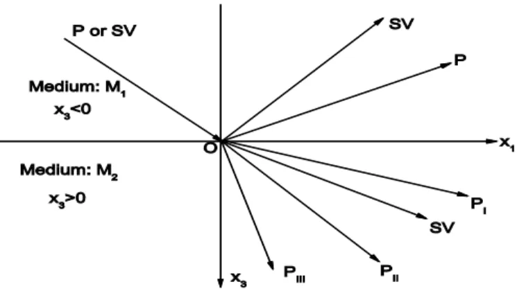
Consider an elastic solid and a porous solid containing liquid filled bound pores and a connected pore space saturated by two-phase fluid having a common boundary. In the cartesian co-ordinate system
x1, , x2 x3
, let the plane x3 0, define this common boundary which is separating the two differentmedia (say, M1 and M2). A wave (P or SV) travels through the elastic medium M1 (i.e., x3 0)
with velocity V0 and incident at the interface making an angle 0 to the x3-axis pointing in to this medium. For two dimensional motion in the x1 x3 plane, unit vector
sin , 0, cos0 0
representsthe phase direction of the incident wave. The incident angle may vary from 0 to 2. Such an
incidence results in two waves reflected back in to elastic medium M1 and four waves refracted to the continuing porous medium M2. The primed quantities separate the medium M1 from M2. The displacement in the elastic medium M1 are expressed as
2
(0) (0) ( ) ( )
1
exp l exp l
j j k k j k k l
l
U S p x t S p x t f
(15)where values 1-2 of the index l represent the P and SV waves, respectively. The fl are relative excitation factors for two reflected waves. We have nj l njl 1 and from Snell's law, p1 ( )l
( ) 1
l l
n V sin0 V0, n2 ( )l 0.
Similarly, for waves refracted in medium M2, the displacements are expressed as
4
1
exp
l l
j j k k l
l
u S p x t f
, (16)
4 4
1 1
exp exp
l l l l l
j j k k l jk k k k l
l l
v L p x t f A S p x t f
, (17)
4 4
1 1
exp exp
l l l l l
j j k k l jk k k k l
l l
w G p x t f B S p x t f
, (18)where L AS and G BS are as given in Sharma and Saini (2012).
The fl are relative excitation factors for refracted waves. We have n n jl jl 1, and from Snell's
law, p1 l n1 l Vl sin0 V0 , n 2l 0.
5 BOUNDARY CONDITIONS
We assume that two half spaces separated by a plane interface x3 0, are in perfect contact.
Therefore, the boundary conditions are continuity of stress components and displacement components along the interface plus one more condition which restrict the flow of two fluids of porous solid in to uniform elastic solid, i.e, at x3 0.
33 33 33 33 31 31
1 1 1 1 3 3 3 3
3 3 3 3
, , , , , ,
d l g d
s l g s
s l g s l g
i ii
iii u v w U iv u v w U
v u v vi u w
(19)
where superposed dot represent the temporal derivative.
The above boundary conditions are satisfied through a system of six linear inhomogeneous equations in f1, f2, f3, f4, f5 and f6. This system of equations is given by
6
0 1
, 1, 2, 3, 4, 5, 6
ij j i j
a f a i
, (20)where the coefficients aij, (i 1, 2, 3, 4, 5, 6) are given as follows:
1 1 1 1 3 3 3 3 2 3
2
2
3 ,
j j j j j j j j j j j j
j p p ik k i ik k i
a S p S p S p A S p B S p
2 3 1 1 3 ,
j j j j
j p
a S p S p
3 13 13 3 11 11 1 ,
j j j j j j
j l g s l g
a A B S A B S
4 31 31 1 33 33 3 ,
j j j j j j
j l g s l g
a A B S A B S
5 3 3 ,
j j j
j k k
a S A S
6 3 3 , 1, 2, 3, 4 ,
j j j
j k k
a S B S j
( 4) ( 4) ( 4) ( 4)
1 3 3
1 1 2 ,
j j j j
j S p S p
a
( 4) ( 4) ( 4) ( 4)
3 1 1 3
2 ,
j j j
j
j
a S p S p
( 4) ( 4
3 4 5 6
)
1 , 3 , 0, 0, 5, 6 ,
j
j j j j
j
S S a a
a a j
(0) (0) (0) (0)
1 1 3
10 S p 2 S p3 ,
a
(0) (0) (0) (0)
20 S3 p1 S1 3 ,
a p
(0) (0)
30 1 , 40 3 , 50 0, 60 0,
a S a S a a
1 11 21 31, 2 12 22 32, 3 13 23 33.
6 ENERGY RATIOS
We now consider the partitioning of energy between different reflected and refracted waves at the surface element of unit area. Following Achenbach (1973), the rate at which the energy is transferred per unit area of the surface is given by the scalar product of surface traction and particle velocity, denoted by P*. The time average of P* over a period, denoted by P* , represents the average
energy transmission per unit surface area per unit time. Thus, on the surface with normal along x3 -direction, the average energy intensities of the waves in the uniform elastic solid medium are defined by
*
13 1 33 3
e
P U U , (21)
with the help of expressions
. .
1
2
f g f g
R R R ,
for two arbitrary complex functions f and g, we obtain the energy ratios giving the rate of average
energy transmission corresponding to each of the reflected and refracted waves to that of the incident wave. These energy ratiosEi (i1, 2), for the reflected P and SV waves, respectively, are defined
as follows:
Figure 1:Shows the schematic diagram of the incidence, reflection and refraction of waves.
* *
0
i ei e
E P P ,
i 1, 2
, (22)where
(0) (0) (0) (
0
0 *0 1 3 3 10) 1 1(0) 1(0) 2 3(0) 3(0) 3
e
P S p S p S S p S p S
R , (23)
1 1
1
1 1
1 1
1*
1 1 3 3 1 1 1 1 3 3 3 5 5
1 1
2
e
P S p S p S S p S p S f f
R , (24)
2 2 2 2
2
2 2
2 2
2*
2 1 3 3 1 1 1 1 2 3 3 3 6 6
e
P S p S p S S p S p S f f
R . (25)
For a saturated porous solid half space with normal along the x3-direction, the average energy flux
is represented through the components Pij given by
31 1 33 3 33 3 33 3
d i j d i j l i j g i j
s s l g
ij
P R R u R R u R R v R R w . (26)
To explain the distribution of incident energy at the free surface of a dissipative porous medium, a matrix defined with its element given by,
*0
ij ij i j e
E R P f f R P ,
i j, 1, 2, 3, 4
, (27)
where bar over an entity implies its complex conjugate. Elements of the matrix P in (27) are defined as follows:
( ) ( ) ( ) ( ) ( ) ( ) ( ) ( ) ( ) ( ) ( ) ( ) ( ) ( ) ( ) ( ) ( )
3 1 1 3 1 11 1 1 33 3 3 3 3 12 13 13 13 3 1
( ) ( ) ( ) ( ) ( ) ( ) ( ) ( ) ( ) ( ) ( ) ( )
1 3 3 11 1 1 33 3 3 22 13 23 13 3
2
i i i i j i i i i i i i i i i i i
ij p p
i i j i i i i i i i i i
P p S p S S X p S X p S p S A B S p
S p S Y p S Y p S A B S p
( ) ( ) ( ) ( ) ( )1 1 3 3
( ) ( ) ( ) ( ) ( ) ( ) ( ) ( ) ( ) ( ) ( ) ( ) ( ) ( )
11 1 1 33 3 3 32 13 33 13 3 1 1 3 3 .
i i i j j k k
i i i i i i i i i i i i j j
k k i j
S p A S
Z p S Z p S A B S p S p B S f f
(28)
The matrices used in the above expressions are defined as
11 12 13 21 22 23
2
, 3
j j j j j j
p
X I A B Y I A B ,
31 32 33
j j j
Z I A B ,
where the superscript '( )'j on matrices A and B means the matrices are evaluated for slowness
vector p of the corresponding refracted wave represented with a value of j
1, 2, 3, 4
. An energymatrix (27) calculates the distribution of the energy among four waves travelling into the dissipative porous medium saturated by two miscible/immiscible fluids. The diagonal entries of the energy matrix
ij
E represent the energy share of the four refracted waves in the medium. The termsE11, E22, E33,
44
E are identified as the refraction (energy) coefficients for PI , PII , PIII and SV waves,
respectively. The sum of all non-diagonal entries of this energy matrix gives the share of the interaction energy among all the refracted waves in the medium. This part of energy is given by
4 4
1 1
RR ij ii
i j
E E E
,yields the conservation of the incident energy across the interface through relation E1 E2 E11
22 33 44 RR 1
E E E E
.
7 NUMERICAL EXAMPLE
A reservoir rock (sandstone) saturated with a liquid and gas is chosen for the numerical model of
porous medium (Garg and Nayfeh, 1986). The solid grains of the rock with bulk modulus Ks
36 GPa, rigidity modulus s 9 GPa, and density s 2650 kg/m3 form a porous frame of porosity 0.3.
f The connected pore space is filled with the bubbles of gas of bulk modulus Kg 0.0037
GPa and density g 100 kg/m3 mixed in a liquid of bulk modulus Kl 2.3 GPa and density l
3
980 kg/m . Both the pore-fluids are viscous and the values chosen for dissipation coefficients are
l
d 1 MPa-s/m2 and dg 0.04 MPa-s/m2. The same liquid with viscosity 10-12 GPa-s and
Reynolds number Re 100 is assumed in the bound pores. The value of ratio Kcap Kl is used to
calculate
1
Kcap (see appendix). Low-frequency propagation regime is ensured withπ×
2 5 kHz
. The elastic medium (M1) has the parameters, 2650 kg/m3, 16.9 GPa, and
28.3 GPa as the values chosen for the density and elastic constants for granite.
8 DISCUSSION
8.1 Reflection and refraction coefficients
We find that the energy ratios of reflected and refracted waves due to either an incident P wave or SV wave depend upon the angle of incidence (i.e., 0). The energy ratios Ei (i 1, 2) and the
energy matrices Eij (i j, 1, 2, 3, 4) defined in the previous section are calculated for a given value
of the incident angle 0 varying from 0 to 90. In the present case, the incidence is considered only for P- and SV - waves. For each incidence, the energy partitions are computed and the conservation
of energy is ensured at the interface of an elastic solid half space and the porous solid half space containing liquid filled bound pores and a connected pore space saturated by two-phase fluid. In the present discussion, E1 and E2 denote the reflection coefficients of P and SV waves, respectively,
whereas E11, E22, E33, E44 denote the refraction coefficients of the PI, PII, PIII, and SV waves,
respectively. The amplitude ratios for the reflected and refracted waves are donated as the energy ratios except these are denoted by notation Z( f ), i.e.,Z11
f1
, Z22
f2
, Z33
f3
,
44 4
Z f , Z1
f5
, and Z2
f6
represent the amplitude ratios of refracted PI , PII , PIII,-SV , reflected P and SV-waves, respectively. Henceforth in the discussionsthe notations for the
energy and amplitude ratios will be used for sake of convenience.
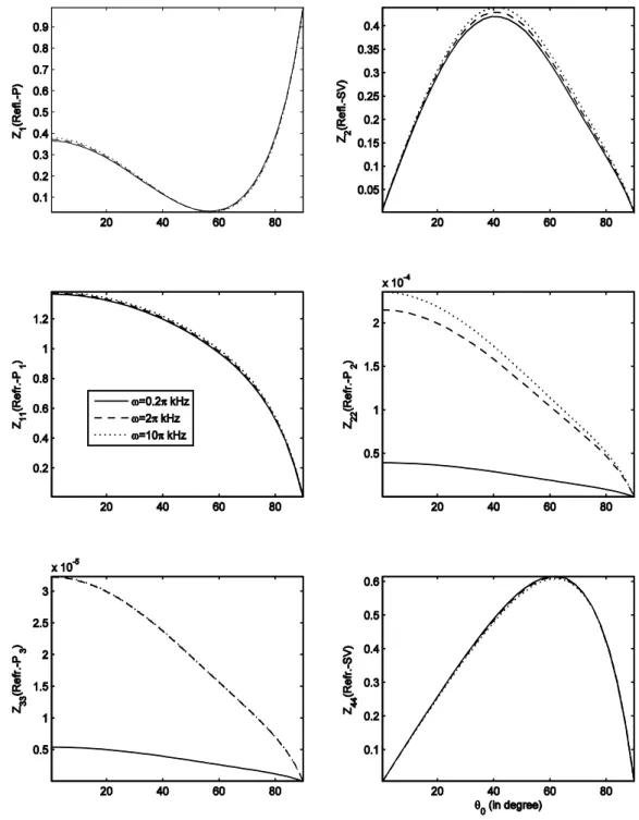
Fig. 2 shows the variation of amplitude ratios with gas saturation for incident P-wave. Z1, Z2 and Z11 increases with increase in the gas saturation. Z44 is almost ineffective to the variation in the gas saturation. Z22 and Z33 are very small yet they show variation with as depicted in Fig. 2. Fig. 3 shows the variation of amplitude ratios with change in the frequency for incident P-wave.
2
Z and Z11 gets strengthen with increase of frequency. Unlike Z2, the amplitude ratio Z44 decreases in magnitude with increase in the frequency. Z1 remains ineffective to the change in the frequency. As Z22 and Z33 are negligibly small yet their amplitude ratios get strengthen with increase in frequency.
Fig. 4 shows the variation of the amplitude ratios with change in the capillary pressure for incident
P-wave. It is evident from the figure that capillary pressure has a little effect upon the variation of amplitude ratios. Whatever effect, if seen, is at the small scale, which is clearly visible in the amplitude
Figure 2: Amplitude ratios (Z1, Z2, Z11, Z22, Z33 and Z44) with 2kHz, 0.2, h 4, 0.001
cap l
K K , 0.2, 0.5, 0.8, and different angles of incidence of P-wave.
ratios Z22 and Z33. Where, Z22 gets weaken with increase in the capillary pressure and Z33 shows an anomalous behaviour with increase of capillary pressure.
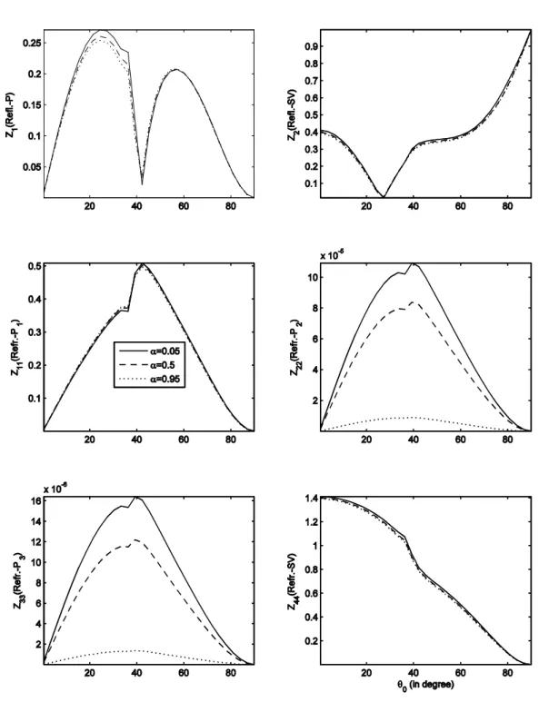
Fig. 5 shows the variation of the amplitude ratios with the change in the fraction of bound liquid film for incident P-wave. Z2 and Z11 show a weakening in the amplitude ratio with increase in the fraction of bound liquid film. Z44 increases with increase in the fraction of bound liquid film. While
Figure 3: Amplitude ratios (Z1, Z2, Z11, Z22, Z33 and Z44) with angle of incidence of P-wave for 0.4, 0.2, h 4, Kcap 0.001Kl, and different values of .
1
Z , first decreases until 58o, thereafter, it gets little strengthen with increase in the fraction of bound liquid film. Thus, Z1 shows a mixed behavior with variation in the fraction of bound liquid film. Again, Z22 and Z33 are very small, but yet their amplitude ratios get weaken with increase in the fraction of bound liquid film.
Figure 4: Amplitude ratios (Z1, Z2, Z11, Z22, Z33 and Z44) with angle of incidence of P-wave for 2kHz,
0.4, 0.2, h 4, and different values of Kcap.
Fig. 6 shows the variation of amplitude ratios with gas saturation for incident SV-wave. Z1 has a mixed behaviour with increase in the gas saturation, i.e., it gets strengthen until the angle of incidence
Figure 5: Amplitude ratios (Z1, Z2, Z11, Z22, Z33 and Z44) with angle of incidence of P-wave for 0.4,
2
kHz, hc 4, Kcap 0.001Kl, and different values of .
42o and thereafter, it starts weakening with increase in the gas saturation. Z2 has no variation till the angle of incidence 28o, after that it increases in strength with increase in the gas saturation till 63o, beyond this some weakening is observed with increase in the gas saturation. Z11 decreases in strength with increase in the gas saturation σ until the angle of incidence 42o, after that increase is observed with . Similarly, Z44 increases little with increase in the gas saturation until 48o, afterwards, it decreases a little with increase in the gas saturation.
Figure 6: The same as Fig. 2, but variation for incidence of SV-wave.
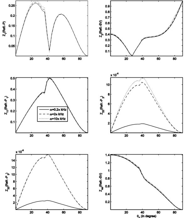
Fig. 7 shows the variation of the amplitude ratios with change in the frequency for incident
SV-wave. Z1 strengthen with increase in the frequency until 42, after this it remains ineffective to the change in frequency. Therefore, mixed behavior is shown with variation in the frequency. Z44 gain in strength with increase in . Z2 increases with increase in , change is most prominent after 48o. While Z11 shows almost no variation with . Z22 and Z33 are very small, but it strengthen with increase in the frequency.
.
Figure 7: The same as Fig. 3, but variation for incidence of SV-wave.
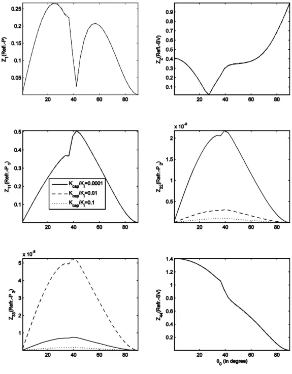
Fig. 8 shows the variation of amplitude ratios with change of capillary pressure for incident SV-wave. Like Fig. 4, Z1, Z2, Z11 and Z44 show almost no variation with increase in the capillary pressure as the variation is observed at the small scale only, which is visible in Z22 and Z33.
Fig. 9 shows the variation in the amplitude ratios with fraction of bound liquid film for incidence of SV-wave. Z44 decreases with increase in . Z1 shows a mixed behaviour, i.e., it gets weaken with increase in the fraction of bound liquid film until the angle of incidence 42o, thereafter, it increases with until 55o, henceforth, no variation till grazing incidence. Therefore, mixed behavior is observed.
Figure 8:The same as Fig. 4, but variation for incidence of SV-wave.
2
Z decreases with increase in . Z11 increases with increase in till 42o, after that, it decreases with increase in the fraction of bound liquid film. Z22 and Z33 are again very small and shows a weakening with increase in the fraction of bound liquid film.
Fig. 10 depicts the variation of the energy partitions with the change of gas saturation for incident
P-wave. E2 increases with increase in the gas saturation and E44 decreases with increase in the gas
saturation. And, E1 and E11 are insensitive to the change of frequency. While, E22, E33 and ERR are very small.
Figure 9: The same as Fig. 5, but variation for incidence of SV-wave.
Fig. 11 depicts the effect of the frequency on the energy partitions for incident P-wave. One could easily draw inference from the figure that E1 and E11 are insensitive to the change in the frequency and if any little is seen that is seen after78. The share of reflected SV-wave (i.e., E2) increases with increase in the frequency. While the energy variation of E44 unlike E2 shows a decrease with increase of the frequency. E22, E33 and ERR are very small and first two shows an increase with increase in the frequency of the incident wave.
Figure 10: Energy ratios (E1, E2, E11, E22, E33, E44 and ERR) with 2kHz, 0.2, h 4, 0.001
cap l
K K , 0.2, 0.5, 0.8, and different angles of incidence of P-wave.
Fig. 12 shows the effect of the capillary pressure on the energy partitions for the incident P-wave. The variation is observed at the small scale. E1 and E44 do not show any change with capillary pressure. E2 shows an increase in the energy with increase in the capillary pressure. Unlike E2, E11 shows a decrease in energy with increase in the capillary pressure.
Fig. 13 shows the effect of bound liquid film on the energy partitions for the incident P-wave. E1 shows a little variation that too after 65, i.e., dips with increase in the fraction of the bound liquid film. E2 decreases with increase in the value of . E44 increases gradually with increase in the
Figure 11: Energy ratios (E1, E2, E11, E22, E33, E44 and ERR) with angle of incidence of P-wave for 0.4, 0.2, h 4, Kcap 0.001Kl, and different values of .
fraction of liquid bound film, i.e., the increase in enhances the energy share of that wave. E11 decreases slightly with increase in the fraction of bound liquid film. Once again E22, E33 and ERR are very small.
Fig. 14 depicts the variation in the energy partitions with the change of gas saturation for incident
SV-wave. E1 increases with increase in the saturation of gas. E2 is insensitive to the change of gas saturation. E11 decreases with increase in the gas saturation and the decrease is quite significant. E44 increases with increase in the gas saturation. E22, E33 and ERR are very small and their variation is as shown in the figure.
Figure 12: Energy ratios (E1, E2, E11, E22, E33, E44 and ERR) with angle of incidence of P-wave for
2 kHz
, 0.4, 0.2, h 4, and different values of Kcap.
Fig. 15 depicts the effect of the frequency on the energy partitions for incident SV-wave. E1 increases in magnitude with increase in the frequency till the critical incidence 39o. E2 is insensitive to the change of frequency. E11 decreases too with increase in the frequency. But, E44 shows an increase with increase in the frequency. However, E22, E33 are small but show an increase in the magnitude with increase in the frequency. ERR shows a decrease in the magnitude with increase in the frequency till 39 and beyond which the pattern is reversed, i.e., increases with increase in the frequency.
Figure 13: Energy ratios (E1, E2, E11, E22, E33, E44 and ERR) with angle of incidence of P-wave for 0.4, 2 kHz
, hc 4, Kcap 0.001Kl, and different values of .
Fig. 16 shows the effect of capillary pressure on the energy partitions for incidence of SV-wave. E1,
2
E and E44 are insensitive to change of capillary pressure. E11 shows an increase in the energy share, that too after 48o. E22, E33 and ERR are again very small and their variation is shown in the figure.
Figure 14: The same as Fig. 10, but variation for incidence of SV-wave.
Fig. 17 shows the effect of bound liquid film on energy partitions for incidence of SV-wave. E1 decreases with increase in the fraction of the bound liquid film till 39o. E2 decreases with increase of the fraction of bound liquid film. E11 increases with increase in the fraction of bound liquid film. E44
Figure 15: The same as Fig. 11, but variation for incidence of SV-wave.
decreases with increase in the fraction of the bound liquid film. E22 and E33 show a decrease with increase in the value of , however, the variation is at small scale. ERR increases till 39
o and beyond
which it decreases with increase in the value of the .
Figure 16: The same as Fig. 12, but variation for incidence of SV-wave.
Figure 17: The same as Fig. 13, but variation for incidence of SV-wave.
9 CONCLUDING REMARKS
The work presented here study the reflection/refraction at the interface of an elastic solid and a partially saturated porous solid containing liquid filled bound pores and a connected pore space saturated by two-phase fluid and the study is for low frequency regime. The porous medium is dissipative due to presence of viscous fluids in the connected pores. The four attenuated waves in the porous medium are identified with complex velocities. The variable gas share in pores enables to represent the pore saturation from all liquid to all gas. Besides, the method used in this paper is not
based on elastic Lame's potentials, but looks directly for the solution of the elastodynamic equation in term of displacement vectors. The study through this method has advantage over the traditional potential method. Firstly, it could be generalized to anisotropic media for the given model. Secondly, it could be used for the inhomogeneous media, but lame’s potential method could not be used for both the cases. Some main observations from the numerical example may be important and hence are explained as follows:
1) The amplitude ratios Z1 and Z2 show variation with change of the saturation of gas, both for the incident P and SV-waves.
2) For incidence of P-wave, Z2, Z11 and Z44 show change with change of frequency. While for incidence of SV-wave, Z1, Z2, and Z44 show a significant change with change of frequency. 3) All the amplitude ratios are insensitive to the change of the capillary pressure.
4) All amplitude ratios are sensitive to change of fraction of bound liquid film.
5) The variation with saturation of gas is observed for E22 and E44 for incidence of P-wave and for incident SV-wave, the variation is prominent for E1, E11 and E44 waves only.
6) The variation of energy with frequency for incidence P-wave is most prominent for reflected SV
and refracted SV-wave. For SV incidence, the significant variation is observed for reflected P, refracted PI and refracted SV .
7) The capillary pressure has an insignificant effect on the energy ratios variation. Any effect, if there, is very small and could be observed for small energy ratios E22 and E33.
8) Variation with bound liquid film is dominant only in case of E2, E11 and E44 waves for incident
P-wave. For incidence of SV-wave, E11 and E44 alone show variation with change of fraction of bound liquid film.
9) The energy ratios E22 and E33 are very small.
10) Angle of incidence render a significant effect on the energy partitions across the surface.
11) The sum of all the energies i.e. reflected as well as refracted at the interface is unity. This shows that there is no dissipation of energy at the interface. Hence, energy is conserved.
Acknowledgements
Author acknowledges the financial support of CSIR, New Delhi (India), in form of SRF through the grant number 09/105(0185)/2009-EMR-I.
References
Achenbach, J.D., (1973). Wave Propagation in Elastic Solids. North-Holland, Amsterdam.
Arora, A., Tomar, S.K., (2007). Elastic waves at porous/porous elastic half-spaces saturated by two immiscible fluids. Journal of Porous Media 10(8): 751-768.
Arora, A., Tomar, S.K., (2010). Seismic reflection from an interface between an elastic solid and a fractured porous medium with partial saturation. Transport in Porous Media 85(2): 375-396.
Bedford, A., Drumheller, D.S., (1983). Theories of immiscible and structured mixtures. International Journal of Engineering Science 21: 863-960.
Biot, M.A., (1956a). The theory of propagation of elastic waves in fluid-saturated porous solid, I. Low-frequency range. Journal of the Acoustical Society of America 28: 168-178.
Biot, M.A., (1956b). The theory of propagation of elastic waves in fluid-saturated porous solid, II. High-frequency range. Journal of the Acoustical Society of America 28: 179-191.
Biot, M.A., (1962). Mechanics of deformation and acoustic propagation in porous media. Journal of Applied Physics 33: 1482-1498.
Bowen, R.M., (1976). The theory of mixtures. Continuum Physics 3, A.C. Eringen Ed., Academic Press, New York. Bowen, R.M., (1980). Incompressible porous media models by use of theory of mixtures. International Journal of Engineering Science 18: 1129-1148.
Brutsaert, W., (1964). The propagation of elastic waves in unconsolidated unsaturated granular mediums. Journal of Geophysical Research 69: 243-257.
Burridge, R., Keller, J.B., (1981). Poroelasticity equations derived from microstructure. Journal of the Acoustical Society of America 70: 1140-1160.
Carcione, J.M., (2007). Wave Field in Real Media. Wave Propagation in Anisotropic, Anelastic, Porous and Electromagnatic Media. Pergamon, Amsterdam.
Denneman, A.I.M, Drijkoningen, G.G., Smeulders, D.M.J., Wapenar, K., (2002). Reflection and transmission of waves at a fluid/porous medium interface. Geophysics 67: 282-291.
Deresiewicz, H., Skalak, R., (1963). On uniqueness in dynamic poroelasticity. Bulletin of Seismological Society of America 53: 793-799.
Edelman, I.Y., (1997). Asymptotic research of nonlinear wave processes in saturated porous media, Nonlinear Dynamics 13: 83-98.
Fellah, Z.E.A., Fellah, M., Depollier, C., (2013). Transient Acoustic Wave Propagation in Porous Media, Modeling and Measurement Methods for Acoustic Waves and for Acoustic Microdevices, Marco G. Beghi (Ed.), ISBN: 978-953-51-1189-4, InTech. DOI: 10.5772/55048.
Garg, S.K., Nayfeh, A.H., (1986). Compressional wave propagation in liquid and/or gas saturated elastic porous media. Journal of Applied Physics 60: 3045-3055.
Gurevich, B., Schoenberg, M., (1999). Interface conditions for Biot's equations of poroelasticity. Journal of the Acoustical Society of America 105: 2585-2589.
Kaynia, A.M., Banerjee, P.K., (1993). Fundamental solutions of Biot's equations of dynamic poroelasticity. International Journal of Engineering Science 31: 817-830.
Kumar, M., Kumari, M., (2014). Reflection of attenuated waves at the surface of a fractured porous solid saturated with two immiscible viscous fluids. Latin American Journal of Solids and Structures 11(7): 1206-1237.
Kumar, M., Saini, R., (2012). Reflection and refraction of attenuated waves at the boundary of elastic solid and porous solid saturated with two immiscible viscous fluids. Applied Mathematics Mechanics 33(6): 797-816.
Kumar, M., Sharma, M.D., (2013). Reflection and transmission of attenuated waves at the boundary between two dissimilar poroelastic solids saturated with two immiscible viscous fluids. Geophysical Prospecting 61(5): 1035-1055. Lo, W.-C., Sposito, G., Mayer, E., (2005). Wave propagation through elastic porous media. Journal of Applied Physics 60: 3045-3055.
Maksimov, A.M., Radkevich, E.V., Edelman, I.Y., (1994). Mathematical model of modulated waves generation is a gas-saturated porous medium. Differential Equations 30: 596-607.
Nikolaevskiy, V.N., (1990). Mechanics of Porous and Fractured Media. World Scientific, Singapore.
Pride, S.R., Berryman, J.G., Harris, J.M., (2004). Seismic attenuation due to wave-induced flow. Journal of Geophysical Research 109, B01 201. DOI: 10.1029/2003JB002639.
Pride, S.R., Gangi, A.F., Morgan, F.D., (1992). Deriving the equations of motion for porous isotropic media. Journal of the Acoustical Society of America 92: 3278-3290.
Sams, M.S., Neep, J.P., Worthington, M.H., King, M.S., (1997). The measurements of velocity dispersion and frequency-dependent intrinsic attenuation in sedimentary rocks. Geophysics 62: 1456-1464.
Santos, J.E., Carbero, J., Douglas, J.Jr., (1990a). Static and dynamic behaviour of a porous solid saturated by a two phase fluid. Journal of the Acoustical Society of America 87(4): 1428-1438.
Santos, J.E., Douglas, J.Jr., Cobero, J., Louvera, O.M., (1990b). A model for wave propagation in a porous medium saturated by a two phase fluid. Journal of the Acoustical Society of America 87: 1439-1448.
Sharma, M.D., Kumar, M., (2011). Reflection of attenuated waves at the surface of a porous solid saturated with two immiscible viscous fluids. Geophysical Journal International 184(1): 371-384.
Sharma, M.D., Saini, R., (2012). Wave propagation in porous solid containing liquid filled bound pores and two-phase fluid in connected pores. Europeon Journal of Mechanics A/Solids 36: 53-65.
Tomar, S.K., Arora, A., (2006). Reflection and transmission of elastic waves at an elastic/porous solid saturated by two immiscible fluids. International Journal of Solids and Structures 43: 1991-2013.
Tuncay, K., Corapcioglu, M.Y., (1997). Wave propagation in poroelastic media saturated by two fluids. Journal of Applied Mechanics 64: 313-319.
Wong, C.G., Bollampally, R.S., (1999). Thermal conductivity, elastic modulus, and coefficients of thermal expansion polymer composites filled with ceramic particles for electronic packaging. Journal of Applied Polymer Science 74: 3396-3403.
Yeh, C.-L., Lo, W.-C., Jan, C.-D., Yang, C.-C., (2010). Reflection and refraction of obliquely incident elastic waves upon the interface between two porous elastic half-spaces saturated by different fluid mixtures. Journal of Hydrology 395: 91-102.
Appendix:
The elastic constants used in (4) are expressed in terms of the elastic constants of the constituents, as follows:
3k 3k 1 0 32 R 33
,
2k 2k 3k 0 22 R 23
,
1k 1k 3k 0 12 R 13
,
k 1, 2, 3
,
g g l l
R , 0 h
,where h is Henry's constant (Garg and Nayfeh, 1986) to represent the mixing of two pore-fluids. For immiscible pore-fluids, i.e., h 0, ik are reduced to ik , which are expressed as follows:
11 Kr 1 1
,
12 Kr 2
, 13 Kr3, Kr
K sKs
1
,
21 Kl 1 1 1
, 22 Kl 2
1
12
,
23 Kl 3 1 3
,
31 Kg 1 1
, 32 Kg
2 2
, 33 Kg
13 3
,
1 1 1 Kg Kl K
1
c l g l g
K K K K K K , 1K
Kg Kl ,
1Kr 1 Kd
,
2 1 [ 2 Kl Kg Kl] K
, 2 1
1
Kl
Kg
K Kr
,
1
Kcap,
3 1 [ 3 Kl Kg Kg] K
, 3 1 Kg
Kl
K Kr
,where Kcap is equivalent bulk modulus for macroscopic capillary pressure (Garg and Nayfeh, 1986)
and Kd is the bulk modulus for drained porous solid. Kj denotes the bulk modulus of phase
( , , , )
j s l g . 1
c
K represents the effective compressibility of mixture of pore-fluids and Kc reduces to Kl when 0. The present work is specifically restricted to the propagation low frequency
harmonic waves so as to follow Poiseuille flow. As a result the capillary pressure in pores is assumed to be independent of frequency and hence a constant Kcap.