Abstract
At conceptual phases of designing a vehicle, engineers need sim-plified models to examine the structural and functional character-istics and apply custom modifications for achieving the best vehi-cle design. Using detailed finite-element (FE) model of the vehivehi-cle at early steps can be very conducive; however, the drawbacks of being excessively time-consuming and expensive are encountered. This leads engineers to utilize trade-off simplified models of body-in-white (BIW), composed of only the most decisive structural elements that do not employ extensive prior knowledge of the vehicle dimensions and constitutive materials. However, the ex-tent and type of simplification remain ambiguous. In fact during the procedure of simplification, one will be in the quandary over which kind of approach and what body elements should be re-garded for simplification to optimize costs and time, while provid-ing acceptable accuracy. Although different approaches for opti-mization of timeframe and achieving optimal designs of the BIW are proposed in the literature, a comparison between different simplification methods and accordingly introducing the best mod-els, which is the main focus of this research, have not yet been done. In this paper, an industrial sedan vehicle has been simplified through four different simplified FE models, each of which exam-ines the validity of the extent of simplification from different points of views. Bending and torsional stiffness are obtained for all models considering boundary conditions similar to experi-mental tests. The acquired values are then compared to that of target values from experimental tests for validation of the FE-modeling. Finally, the results are examined and taking efficacy and accuracy into account, the best trade-off simplified model is presented.
Keywords
FE modeling, conceptual design, BIW, automotive structure de-sign, torsional stiffness, bending stiffness.
Investigation on the optimal simplified model of
BIW structure using FEM
Mohammad Hassan Shojaeefarda Abolfazl Khalkhalib
Morteza Sarmadic* Naqi Hamzehid
a,b,c,dAutomotive Simulation and Optimal
1 INTRODUCTION
Highly competitive nature of the automotive industry propels car manufacturers toward producing safer cars with lower price and better dynamic performance in a shorter time frame. This necessitates automotive engineers to consistently investigate safety and reliability characteristics of the vehicle to reach the optimum designs which can meet often conflicting design criteria. In recent years, use of computer-aided engineering (CAE) methods has been a good asset for engineers, particularly, at the early stages of body-in-white (BIW) structure design. However, parameterization of the design as a detailed FE model could be costly and time-consuming (Volz, 1999), also exact geometrical configu-ration of the vehicle may not be completely determined. Additionally, exact investigation of manifold effects on the vehicle dynamic performance, after each series of design optimization, in conceptual steps could be challenging, if not impossible. As a result, proposing a simplified BIW model which can efficiently demonstrate similar functional performance and safety attributes to the final product is very desirable. By means of this optimal model, without any need for extensive prior knowledge of the vehicle dimensions and geometry, engineers will be able to assess different design characteristics and apply custom modifications more easily.
Several literatures have been contributed to proposing innovative approaches as well as models for optimal simplification of BIW at conceptual stages (Mundo et al., 2010; Doke et al., 2012; Chen and Zuo, 2014; Zuo, 2015). Mundo et al. (2009) proposed an engineering approach for replacement of beam-like structures and joints in a vehicle model. The proposed replacement methodology was based on the reduced beam and joint modelling approach, which involved a geometric analysis of beam-member cross-sections and a static analysis of joints. Dai and Duan (2009) presented a beam element modelling applying a recurrent neural network to extract the input/output relationship between the crash dynamic characteristics and beam element features and showed that the predicted beam element model enables generating essential crash dynamic characteristics for concept BIW design evaluation at a reasonable level of accuracy. Donders et al. (2009) presented a reduced beam and joint modeling approach to analyze and optimize the low-frequency vehicle performance. They also analyzed concept modifications in the body beam-like sections and in the joints using the body reduced modal model. Zuo et al. (2012) exploited a semi-rigid beam element (SRBE) that consisted of a beam element with two semi-rigid connections at the ends to simulate the flexibility of joint. They also developed special
finite element software for structural modeling and analysis of BIW (SMAB) in .NET framework. Zuo (2013) introduced object-oriented graphics interface design and optimization software for cross-sectional shape of automobile body, which can be used at the conceptual phases of automotive design. This software was designed to optimize the weigh and the stiffness of the thin-walled beams using Genetic algorithm.
The outline of this paper is as follows: in section 2, the process for developing a simplified BIW model of one sedan vehicle is introduced. Using realistic experimental results as target values allows us to validate the FE modeling and the results of this study. 4 different simplified BIW models including a simplified structural surface model (SSSM) based on SSS theory (Pawlowski, 1969), a
beam-based model for one side of the vehicle (BMOS), a beam-based model for entire of the vehicle
cabin (BMEC) and a coupled beam-surface model (CBSM), each of which following a different sim-plified modeling approach, are proposed in section 3. Their structural behavior in terms of deformation and stiffness under static bending and torsional loadings are then evaluated in section 4 and 5, re-spectively.
Torsional and bending stiffness, which are two paramount factors in vehicle safety, are calculated in each model. Finally in section 6, the optimal model considering a trade-off between requisite knowledge and capability in prediction of accurate bending and torsional stiffness, is selected as the most reliable and accurate simplified model which can be used at conceptual design stage of BIW.
2 TARGET SETTING
Target values for bending and torsional stiffness are specified based on experimental tests of an in-dustrial sedan vehicle. The torsional and bending of the reference vehicle are 16700 (N.mm/⁰) and 14800 (N/mm), respectively.
3 SIMPLIFIED MODELING OF BIW
The reference sedan vehicle exterior style is depicted in Figure 1. In all presented simplification ap-proaches there are 3 steps: 1) a simplified CAD model of the main vehicle under-body subcomponents is created and assembled. In this stage there is no need for detailed specification of welding spots, 2) vehicle cabin structure which is comprised of rails and pillars is simplified as beam elements. Three planar moments of area for each pillar and rail section are calculated. Subsequently, moments of area are specified to each rail and pillar in the FE solver. The position of centroid for each section is regarded based on the actual geometry of the vehicle, 3) torsional and bending stiffness of the con-ceptual model are then calculated under equal boundary conditions. This stage uses both numerical and analytical tools to evaluate the model deflection under quasi-static loading. The obtained torsional and bending stiffness are then compared to the target values.
In this section, 4 simplified models regarding some similarities and differences are proposed. A good simplified model should be able to represent similar structural behavior to the original model and simultaneously be easy to modify, thus, allowing designers to improve their basic designs at any stage.
3.1 Simple structural surface model (SSSM)
The simple structural surfaces (SSS) method was first introduced by Pawlowski (1969) and has been proved to be a good method at the conceptual stage of the design process or when there are funda-mental structural changes (Pawlowski, 1969; Brown et al., 2002; Mallen, 2010).
Figure 1: Exterior style of the vehicle used as the basis of simplified modeling.
The procedure is to model or represent the structure of the vehicle as a number of plane surfaces. Each plane surface or simple structural surface (SSS) must be held in equilibrium by a series of forces (Brown et al., 2002). These forces are resulted from the weight of different components attached to them, for instance the weight of the engine/transmission applies force on the longitudinal and lateral engine rails. A simple structural surface (SSS) is a plane structural element or subassembly that can be considered as rigid only in its own plane (Pawlowski, 1969; Brown et al., 2002). Figure 2 shows such a structural element where the length a and height b are pretty large considering its thickness
t.
Figure 2: Definition of a SSS element from (Brown et al., 2002).
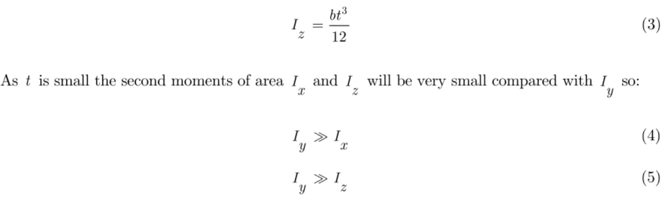
Considering planar sections through the element in xy and yz planes, the second moments of area can be obtained by the standard formulae as:
3
12
at I
x (1)
3
12
tb I
3
12
bt I
z (3)
As t is small the second moments of area I
x and Iz will be very small compared with Iy so:
I I
y x (4)
I I
y z (5)
Therefore the SSS is capable of resisting bending moments about the y-axis, but has little or no resistance for moments about the x-and z-axes, additionally, direct loads F
x and Fz acting in the
plane of the SSS will also be satisfactorily resisted but normal local loads along the y-axis will of
course result in flexing of the SSS by bending about the z-or x-axes (Brown et al., 2002).
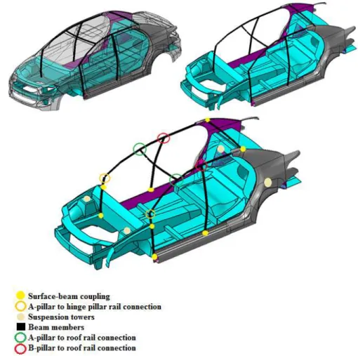
A model has been developed based on SSS elements (see Figure 3). This model includes one extremely simplified side panel of the body and structural members including: A-pillar, B-pillar, hinge, rocker, roof rail and C-pillar are simplified as beam members. For simulating flexible joint connec-tions, rigid joints are replaced by torsional springs. Corresponding stiffness values are given in Table 1. These values are common for a vehicle similar to the dimensions of the reference vehicle in this study (see Mallen (2010)). Moments of area in x y plane are also calculated for each beam cross-section and used as input data. Cross-cross-section geometry as well as planar moments of area for each beam element are given in Figure 4 and Table 2, respectively.
Figure 3: Modeling of one side of the vehicle BIW using SSS simplification.
Torsional stiffness values of connections
Joint number Connection Torsional stiffness (N.mm/rad) Joint-1 B-pillar to Roof Rail 10
Joint-2 A-pillar to Roof Rail 10 Joint-3 A-pillar to Hinge Rail 5000
Table 1: Torsional stiffness for flexible joints used in simplifications.
Figure 4: Cross-section geometry of beam members.
Planar moments of inertia of sections (plane xy)
xx
I (mm4) Iyy(mm4)
xy
I (mm4) A(mm2)
Roof 3.31E+04 3.31E+04 -3.82E-08 2.42E+02 Rocker 1.18E+06 3.02E+06 -5.81E-08 6.23E+02 A-above 9.98E+04 5.74E+05 4.34E-08 3.28E+02 Hinge-above 8.12E+05 1.28E+06 7.77E-08 4.98E+02 Hinge-below 1.15E+06 2.45E+06 4.67E-08 5.65E+02 C-above 5.96E+05 9.34E+06 -5.29E-11 7.84E+02 C-below 7.91E+05 3.16E+06 2.12E-10 6.11E+02 B-above 1.26E+05 9.20E+05 2.13E-08 3.83E+02 B-below 7.15E+05 9.29E+06 -3.91E-07 7.81E+02 Joint-1 1.77E+04 3.05E+05 3.96E-08 2.52E+02 Joint-2 4.59E+04 6.92E+05 2.30E-08 3.31E+02 Joint-3 7.21E+05 2.34E+06 -3.20E-08 5.28E+02 Joint-4 2.33E+04 7.45E+05 5.75E-08 3.35E+02 Joint-5 4.86E+05 8.62E+05 -2.81E-09 3.90E+02 Joint-6 2.52E+05 4.94E+05 -6.27E-08 3.24E+02
3.2 Beam-based model for one side of the vehicle (BMOS)
This model is somehow similar to SSSM in geometry; however, there are two fundamental changes: 1) quarter panel surface has been added in the modeling considering more geometric details, and 2) the model is three-dimensional. It should be noted that because of complexity of the quarter panel geometry, simplification of this panel to beam members in SSSM increases the error percentage. Simulation data of joints and connections is depicted in Figure 5. For a more realistic simulation of joint connection between C-pillar and rocker rail, two ends of the roof rail and rocker rail are coupled to upper and lower ends of the quarter panel, respectively. In comparison to SSSM, this model mainly investigates the role of consideration of modeling the quarter panel surface, and the new three-dimen-sional simulation space.
Figure 5: BMOS model and its connections types.
3.3 Beam-based model for entire of the vehicle cabin (BMEC)
In this model, BIW main structural members have been simplified to beams. Lateral cross members as well as vehicle longitudinal tunnel rail are added as beam members with thin-walled rectangular cross-section. The main focus of this model is on the effect of added reinforcement of lateral members; also, the impact of lateral joint connections. Figure 6 shows the model connections and geometry configuration. 4 flexible joint connections are considered in which all DOFs except rotation along x,
y and z axes are restrained.
3.4 Coupled beam-surface model (CBSM)
In CBSM, effects of two important modifications have been investigated, firstly, the influence of more detailed surface-based modeling instead of beam simplification, secondly, the nature of interactions between beams and surfaces in FE modeling. The same connections in BMEC were specified for this
model as well. Additionally, hinge pillar was coupled to upper rails as shown in Figure 7. For simu-lation of flexibility of the connections between hinge and upper rails, the coupled node only can rotate along three-dimensional axes.
Figure 6: Configuration of BMEC model connections and geometry.
4 FINITE-ELEMENT (FE) SIMULATION CRITERIA
ABAQUS commercial software was used for running FE simulation. All simulations were performed in implicit mode. The meshing size was set on 20 mm where no further improvement was achieved. The meshing style was considered advanced 2D quadratic-triangular type, which is appropriate for surface meshing. The constitutive material was regarded as steel with shear modulus and elastic modulus of 79.3 GPa and 207 GPa, respectively. Join-Euler joints were also used for simulation of flexible connections.
5 BENDING STIFFNESS ANALYSIS
The methodology implemented in specification of boundary conditions is based on actual industrial tests. Despite dissimilarity in nature of the presented models, an identical approach has been taken toward calculation of both torsional and bending stiffness in all of them which is discussed in the following.
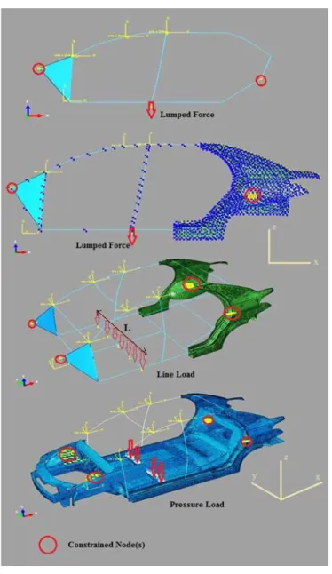
5.1 Boundary conditions under bending loading
The boundary conditions in bending analysis are depicted in Figure 8. All models were clamped at front and rear suspension towers, and front suspension attachments were simplified as rigid plates. In SSSM model, rear and front suspension towers were simplified to one node with fixed transla-tional DOFs. In BMOS, BMES and CBSM, translatransla-tional DOFs of 25 nodes in each front and rear suspension towers were fixed. It must be pointed out that these nodes are distributed homogenously, covering the suspension tower interface with upper part of BIW. In BMOS asymmetric DOFs were specified to entire the model elements. This feature restricts deformation of the model exclusively to
xz plane. For calculation of the bending stiffness of the model structure in SSSM and BMOS, a
concentrated (lumped) force is applied where B-pillar is attached to rocker rail. Similarly, in BMEC and CBSM, a line load and a pressure load is applied to the lateral stiffener, respectively.
5.2 Calculation of bending stiffness
Subsequently, displacement along the applied load is measured and the stiffness is calculated through the following relationship:
b
F
k
(6)
where F is the total vertical force leading to a bending moment and is the maximum displace-ment along the force direction in rocker rail. It must be pointed out that F in equation (6) have a general meaning. In fact when we apply concentrated force f on each side-panel in SSSM and BMOS,
2
F f , in case of line load fl in CBSM, F f Ll , and lastly for pressure load p in BMES,
F pA , where A is the surface on which the pressure is applied. It can come to mind why a
similar concentrated force as in SSSM or BMOS has not been considered in 3D models. There exist two major reasons for this: 1) during the FE simulations, it was tried to avoid the effects of
Figure 8: Boundary conditions in all presented models.
Bending stiffness (N/mm) Error percentage (%)
SSSM 7142 51.7
BMOS 12500 15.5
BMEC 12614 14.7
CBSM 12714 14.0
Target value 14800 -
Table 3: Obtained bending stiffness of the models.
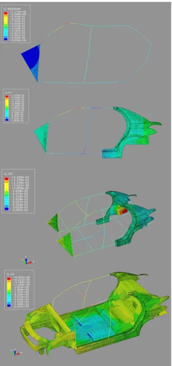
Figure 9: Deformation of the models under bending loading.
6 TORSIONAL STIFFNESS ANALYSIS
Investigation of torsional stiffness in SSSM in comparison to other models follows a different proce-dure. In BMOS, BMEC and CBSM, due to complexity of the geometry, investigation of torsional stiffness is exclusively based on numerical simulation. However, calculation of torsional stiffness in SSSM needs a coupling between both analytical and numerical analyses. In the following a theoretical approach for calculation of torsional stiffness considering SSS theory has been introduced.
6.1 Torsional stiffness analysis in SSSM
According to Mallen (2010), acquiring torsional stiffness in a SSS-type simplified vehicle body can be briefly summarized in 3 stages:
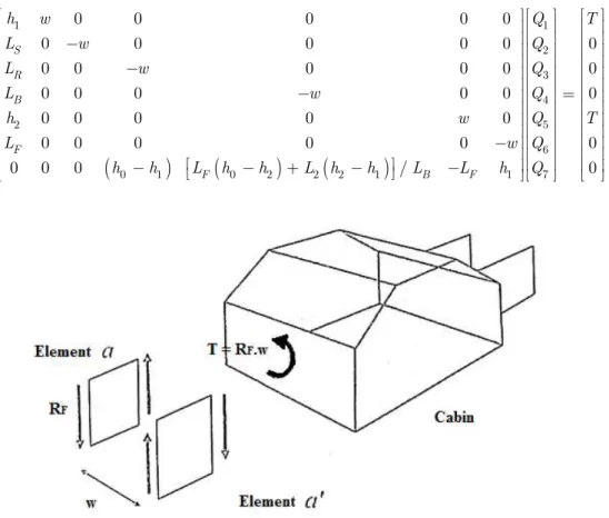
1- All BIW panels are simplified to SSS elements and a torque of T is assumed to apply to dash panel (see Figure 10). Static equilibrium is considered for each panel, and corresponding equations are derived accordingly. These equations provide a matrix as:
1 1 2 3 4 2 5 60 1 0 2 2 2 1 1 7
0 0 0 0 0
0 0 0 0 0 0
0 0 0 0 0 0
0 0 0 0 0 0
0 0 0 0 0
0 0 0 0 0 0
0 0 0 / 0
S R B
F
F B F
h w Q T
L w Q
L w Q
L w Q
h w Q T
L w Q
h h L h h L h h L L h Q
(7)
Figure 10: First step in calculation of torsional stiffness in SSSM, where all panels are simplified to SSS elements and torque T is applied to the dash front panel from Mallen (2010).
1 7
Q Q are reaction shear forces between panels, and parameters in left-hand side matrix are
Figure 11: Shear forces exerted between panels (Mallen, 2010).
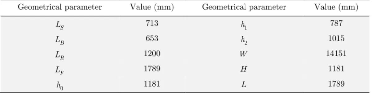
Geometrical parameter Value (mm) Geometrical parameter Value (mm)
S
L 713
1
h 787
B
L 653 h2 1015
R
L 1200 W 14151
F
L 1789 H 1181
0
h 1181 L 1789
Table 4: The geometrical parameters of the SSS modeling for calculation of torsional stiffness.
2- Effective shear modulus of the side panel is also calculated by:
t eff F H GL
(8)
where F is the applied shear force on the roof rail, is cabin deflection along F direction and H
and L are the height and wheelbase length, respectively. The boundary conditions are schematically
depicted in Figure 12. The applied torque T and the parameter of H L are 1000 N.mm and 0.66,
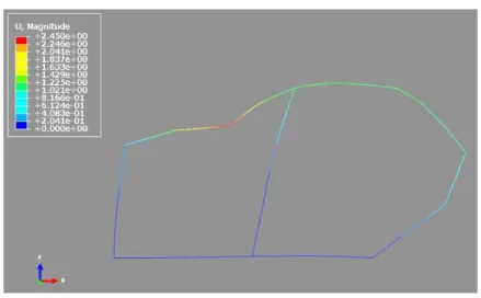
respectively. Figure 13 shows the FE model deformation underF 994N . Resultantly,
f t ef
G was
achieved 547 N/mm.
Figure 13: Deformation of SSSM under shear loading.
3- Torsional stiffness is finally calculated using the given formulation:
2
1
1
area of surface
t
i
t eff surf i k q i t G
(9)where kt is torsional stiffness, t denotes the panel thickness and is assumed constant in all panels, i
is the number of the simplified panel and q is shear flow in panels which can be calculated by:
the edge to wich is applied
i i
Q q
Q
(10)
It has been proved that torsional stiffness is considerably governed by the stiffness of the side panels; in fact, at early stages of design, there is no need for investigation of the effective shear modulus for other panels. Thus, in the present paper,
Gt effhas been calculated only for side panels,and for other panels it has been considered 79.3 Gpa. The obtained torsional stiffness is shown in table 5; further discussion will be done in section 7.
Torsional stiffness (N.mm/degree) Error percentage
SSSM 23762 42.28
BMOS 19857 18.90
BMEC 17745 6.25
CBSM 17375 4.04
Target value 16700 -
6.2 Torsional stiffness in BMOS, BMES and CBSM
6.2.1 Boundary conditions
In these models, translational and rotational DOFs of 25 nodes in each rear suspension towers are constrained and free, respectively. This feature simulates the conditions near to experimental tests. Moreover, asymmetric boundary conditions in ABAQUS program are specified for all nodes of BMOS for a more realistic planar deformation. To apply the torsional torque to front panel of BIW, a couple of forces with opposite directions have been applied in front suspension towers. The torque is then calculated by:
C
T wF (11)
where w is the lateral distance between two front suspension towers which is 1451 mm and FC is
the applied force which is 1000 N. Boundary conditions for each model is depicted in Figure 14.
Figure 14: Boundary conditions of models in calculation of torsional stiffness.
6.2.2 Calculation of torsional stiffness
Calculation of torsional stiffness has been performed by the formulation as:
1 2
tan
t
T k
w
(12)
where is the maximum vertical displacement of the front suspension tower. Corresponding values of obtained torsional stiffness as well as deformation of models are presented in table 5 and Figure 15, respectively.
7 DISCUSSION ON THE RESULTS
A comparison between error percentage in obtained torsional and bending stiffness for all models is depicted in Figure 16. The overall percentage of error in all models is relatively low which illustrates the validity of the FE modeling. Accordingly, as predicted, at the same time with observing an increase in the complexity and requisite data of the FE model, the percentage of error in the calculated torsional and bending stiffness decreases. SSSM has the highest error which is the indicator of the necessity of considering numerical methods as cornerstone rather than exclusively relying on theoret-ical formulations at conceptual stage. The percentage of error in bending and torsional stiffness of SSSM, in comparison to BMOS, is 36% and 24% higher, respectively, which highlights the need for modeling quarter-panel as a surface. From BMOS to BMEC the difference is rather negligible (about 1% in bending stiffness and 12% in torsional stiffness).
Figure 16: Comparison of the percentage of error in different models.
This finding indicates that without having extensive knowledge about the lateral dimensions and cross sections, by modeling side panels, design engineers will still be able to estimate the bending rigidity of the vehicle with acceptable accuracy. Nevertheless, adding lateral members can improve the accuracy. In CBSM, there exists 4% of error in torsional and 14% in bending stiffness. It must be pointed out that a coupled beam-surface concept model reflects an overestimated value for bending stiffness. There can be two explanations for such an observation, firstly, the joint connection simpli-fication between beam and surface elements can lead to error. Secondly, surface imperfections such as holes and geometrical defects are ignored in simplified CAD modeling. In addition, limited beam section variation may cause some inaccuracies. Some researchers have suggested correction factors for moments of area of beams (Vinot et al., 2001; Lee et al., 2012); however, proposing new methods for reduction of the noted effects is not of the present study.
Moreover, from BMOS to BMES the error percentage has fallen by 16 %. This finding indicates that without prior knowledge about lateral BIW elements, designers are still able to assess and predict the torsional and bending stiffness with an acceptable level of accuracy.
0 10 20 30 40 50 60
SSSM BMOS BMEC BMES
p ercen ta g e o f erro r ( %)
Bending Stiffness Error Torsional Stiffness Error
Taking accuracy, cost and prior knowledge into account, BMOS can be considered as the trade-off optimal simplified BIW model among all. Engineers can investigate custom changes in BIW at extreme ease using the methodology which concentrate on quarter-panels, inner layer structures and structural rails and pillars.
8 CONCLUSIONS
In the presented research, 4 different approaches for BIW simplified modeling were introduced and investigated. The models were formed based on different coupling of surface and beam elements as well as different extent of geometric simplification. Torsional and bending stiffness, regarding the same boundary conditions in experimental tests, were calculated successfully for each model. Obtained results were compared and evaluated in details. It was shown that SSS modeling gives acceptable results for bending stiffness, however, under torsional loading the error percentage increases consid-erably. The implemented approach in BMOS was proved to lead to a good trade-off model considering simplicity of the use, the ability to apply custom modification as well as level of accuracy in prediction of safety attributes.
References
Brown, J.C., Robertson, A.J., Serpento, S.T., (2002). Motor vehicle structures: concepts and fundamentals. Butter-worth-Heinemann. Oxford, UK.
Chen, W., Zuo, W., (2014). Component sensitivity analysis of conceptual vehicle body for lightweight design under static and dynamic stiffness demands. International Journal of Vehicle Design 66(2): 107-23.
Dai, Y., Duan, C.. (2009). Beam element modelling of vehicle body-in-white applying artificial neural network. Applied Mathematical Modelling33(1): 2808–2817.
Doke, P., Fard, M., Jazar, R., (2012). Vehicle concept modeling: A new technology for structures weight reduction. Procedia Engineering 49: 287–293.
Donders, S., Takahashi, Y., Hadjita, R., Van Langenhovea, T., Brughmansa, M., Van enechtenb, B., Desmetb, W., (2009). A reduced beam and joint concept modelling approach to optimize global vehicle body dynamics. Finite Ele-ments in Analysis and Design 45: 439–455.
Lee, S.B., Park, J.R., Yim, H.J., (2012). Numerical approximation of vehicle joint stiffness by using response surface method. International Journal of Automotive Technology 3(3): 117–122.
Mallen, D.E., (2010). Fundamentals of automobile body structure design. SAE International. Pennsylvania, USA. Mundo, D., Donders, S., Hadjit, R., Stigliano, G., Mas, P., Van der auweraer, H., (2010). Concept modelling of auto-motive beams, joints and panels. In: Proceedings of the 3rd WSEAS International Conference on Finite Differences, Finite Elements, Finite volumes & Boundary Elements Bucharest. Romania, April 20-22.
Mundo, D., Hadjitb, R., Dondersb, S., Brughmansb, M., Masb, P., Desmetc, W., (2009) Simplified modelling of joints and beam-like structures for BIW optimization in a concept phase of the vehicle design process. Finite Elements in Analysis and Design 45: 456–462.
Pawlowski, J., (1969). Vehicle body engineering. Business Books Limited. UK.
Vinot, P., Cogan, S., Piranda, J., (2001). Shape optimization of thin-walled beam-like structures. Thin-Walled Structures 39(7): 611–630.
Zuo, W., (2013). An object-oriented graphics interface design and optimization software for cross-sectional shape of automobile body. Advances in Engineering Software 64: 1–10.
Zuo, W., (2015). Bi-level optimization for cross-sectional shape of thin-walled car body frame constrained with sta- tic and dynamic stiffness. Proc IMechE Part D: Journal of Automobile Engineering, In press. DOI:
10.1177/0954407014551585.
Zuo, W., Lia, W., Xu, T., Xuan, S., Na, J., (2012). A complete development process of finite element software for body-in-white structure with semi-rigid beams in. NET framework. Advances in Engineering Software 45: 261–271.