Abstract
This study deals with the dynamic behavior of a cracked beam subjected to a concentrated force traveling at a constant velocity. Dynamic analyses for a hinged-hinged cracked beam resting on elastic supports under the action of a moving load are carried out by the finite element method. For the beam having rectangular cross-section, element formulation for crack element is developed by using the principles of fracture mechanics. In the numerical analysis, Newmark integration method is employed in order to calculate the dynamic response of the beam. The effects of crack depth, crack location, elastic support and load velocity on the dynamic displacements calculated for different locations on the beam are investigated. The results related to the dynamic response of the beam are presented in 3D graphs.
Keywords
Cracked beam, Finite element analysis, Newmark integration, Moving load, Elastic support.
Dynamic Analysis of Elastically Supported Cracked Beam
Subjected to a Concentrated Moving Load
1 INTRODUCTION
Recently, the dynamic analysis of the engineering structures subjected to moving loads has gained great importance. The engineering structures with moving loads often come out in buildings, bridg-es, railways and cranes. Moreover, the cracks can be seen in engineering structures due to reasons like erosion, corrosion, fatigue or accidents. The presence of a crack can not only cause a local varia-tion in the stiffness, but many also affect the dynamic behavior of the entire structure to a consid-erable extent. In this context, dynamic behavior of an engineering structure subjected to moving loads is affected with the presence of a crack.
Many investigations on the dynamic behaviour of the different isotropic structures subjected to moving loads have been carried out. Olsson (1991) has presented the fundamentals of the moving load problem for an isotropic beam. Rao (2000) has studied the dynamic response of multi-span Euler–Bernoulli beam to moving loads. Wang (1997) has investigated the forced vibration of multi-span Timoshenko beams. The effects of multi-span number, rotary inertia, and shear deformation on the
Hasan Ozturk Zeki Kiral Binnur Goren Kiral
Department of Mechanical Engineering, Dokuz Eylul University 35397, Buca, Izmir, Turkey
[email protected] [email protected] [email protected]
http://dx.doi.org/10.1590/1679-78252195
Latin American Journal of Solids and Structures 13 (2016) 175-200
maximum moment, maximum deflection, and critical load velocity were investigated in this study. The moving force identification for a Timoshenko beam model has been given and the results, obtained for an Euler–Bernoulli beam model, have been compared by Law and Zhu (2000). Esmai-lzadeh and Ghorashi (1997) have analyzed the effects of shear deformation, rotary inertia and the length of load distribution on the vibration of the Timoshenko beam subjected to a traveling mass. Hino et al. (1985) has investigated the vibration of a beam subjected to a moving load by using the Galerkin finite element formulation.
The deterministic and random vibration analyses of a nonlinear beam resting on an elastic foundation subjected to a moving load have been performed by Chang and Liu (1996). Thambi-ratnam and Zhuge (1996) have developed a simple procedure based on the finite element method for treating the dynamic analysis of beams on an elastic foundation subjected to moving point load, where the foundation was modelled by springs of variable stiffness. A method for the dynamic analysis of elastic beams subjected to dynamic loads induced by the arbitrary movement of a spring-mass-damper system has been presented by Lin and Trethewey (1990). In this study, the governing equations have solved with a Runge-Kutta integration scheme to obtain the dynamic response for both the supporting beam and the moving system. Kidarsa et al. (2008) have proposed a new numerical integration scheme in force-based elements, which enables to computing the inter-nal force history at any location along a structural member under the effect of moving load. Gören Kıral and Kıral (2009, 2008) and Kıral (2009) have studied the dynamic response of a symmetric laminated composite beam subjected to a concentrated moving load with constant velocity consider-ing the effect of different boundary conditions, foundation stiffness and dampconsider-ing.
for-Latin American Journal of Solids and Structures 13 (2016) 175-200
lated using Hamilton's principle and the assumed mode method by Lee and Ng (1994). In this study, the beam has modeled as two separate beams divided by the crack. Mahmoud and Abou Zaid (2002) have developed an iterative modal analysis approach to determine the effect of trans-verse cracks on the dynamic behavior of simply supported undamped Bernoulli-Euler beams subject to a moving mass. Lin and Chang (2006) have developed an analytical method to present the dy-namic response of a cracked cantilever beam subject to a concentrated moving load. The cracked beam system has modeled as a two-span beam and each span of the continuous beam is assumed to obey Euler–Bernoulli beam theory. Yang et al. (2008) have investigated the free and forced vibra-tion of slender funcvibra-tionally graded material (FGM) beams with open edge cracks under a combined action of an axial compression and a concentrated transverse moving load. Kargarnovin et al. (2012) have presented dynamic response of a delaminated composite beam under the action of mov-ing oscillatory mass with the Poisson’s effect, shear deformation and rotary inertia. Esen (2015) has presented a combined plate element for the analysis of transverse and longitudinal vibrations of a thin plate which carries a load moving along an arbitrary trajectory with variable velocity.
In this study, the dynamic behavior of a cracked beam subjected to a concentrated force travel-ing at a constant velocity is investigated by ustravel-ing the finite element method. The end conditions of the beam are assumed to be hinged-hinged. The effect of the elastic support is included in the study by using the linear springs distributed to the nodes of the beam. For the rectangular cross-section beam, a crack element is modeled by using the principles of fracture mechanics. The Newmark inte-gration method, which is frequently used in the structural dynamic analyses, is employed in order to calculate the dynamic response of the beam. The effects of crack depth, crack location, elastic support and load velocity on the dynamic displacements of the beam are investigated. The results are presented in 3D graphs.
2 CALCULATION OF THE LOCAL FLEXIBILITY
A crack on a beam introduces considerable local flexibility due to the strain energy concentration in the vicinity of the crack tip under load. The idea of an equivalent spring i.e. a local compliance is used to quantify, in a macroscopic way, the relation between the applied load and the strain con-centration around the tip of the crack (Karaagac et al., 2009). A beam element of rectangular cross-section has an edge crack with a tip line parallel to the z-axis, i.e. with a uniform depth. A general-ized loading is indicated by three general forces: an axial force P1, shear force P2 and bending
mo-ment P3 as seen in Figure 1(a).
Latin American Journal of Solids and Structures 13 (2016) 175-200
In this work, the cross section of the beam is assumed to be rectangular. The additional strain energy due to the existence of a crack can be expressed as (Karaagac et al., 2009; Zheng and Kes-sissoglou, 2004):
c
c A
G dA
P =
ò
(1)Where G is the strain energy release rate function and Ac is the effective cracked area. The strain energy release rate function G can be expressed as (Zheng and Kessissoglou, 2004)
(
)
2 21 2 3 1
1
I I I II
G K K K K
E
é ù
= êê + + + úú
¢ ë û (2)
In this expression,E¢ =Efor plane stress problem and 2
/ (1 )
E¢ =E -n for plane strain prob-lem (Karaagac et al., 2009; Zheng and Kessissoglou, 2004), where E denotes the modulus of elastic-ity and denotes the poissons's ratio. KIn and KIIn (n=1,2,3) are the stress intensity factors of the two modes of fracture (opening and sliding types) corresponding to generalized loading Pn, respec-tively. The stress intensity factor KI2 is ignored due to the Euler beam theory and KI1 is given as (Ibrahim et al., 2013; Shen and Pierre, 1994).
1 3 2
1 3 2 2
6
1 , 2 , 3
I I II
P P P
K F K F K F
bh h bh h bh h
x x x
px æ öç ÷÷ px æ öç ÷÷ px æ öç ÷÷ = ççç ÷÷ = ççç ÷÷ = ççç ÷÷
è ø è ø è ø (3)
where
3
0.752 2.02 0.37 1 sin tan 2 2 1( ) cos 2 2 s s s F s s s p p p p
æ æ öö
æ ö÷ ç ç ÷÷
ç ÷ + + ç - ç ÷÷
ç ÷ ç ç ÷÷
ç ÷ ç ÷÷÷
ç ç è ø
è ø è ø
= æ ö æ ö
÷ ÷
ç ÷ ç ÷
ç ÷ ç ÷
ç ÷ ç ÷
ç ç
è ø è ø
(4)
4
0.923 0.199 1 sin tan 2 2 2( ) cos 2 2 s s F s s s p p p p
æ æ öö
æ ö÷ ç ç ÷÷
ç ÷ + ç - ç ÷÷
ç ÷ ç ç ÷÷
ç ÷ ç ÷÷÷
ç ç è ø
è ø è ø
= æ ö æ ö
÷ ÷
ç ÷ ç ÷
ç ÷ ç ÷
ç ÷ ç ÷
ç ç
è ø è ø
(5)
2 3
1.122 0.561 0.085 0.18 3( )
1
s s s
F s
s
- + +
=
- (6)
Latin American Journal of Solids and Structures 13 (2016) 175-200
The elements of the overall additional flexibility matrix cij can be expressed as (Karaagac et al., 2009; Zheng and Kessissoglou, 2004).
2
( ,
1, 2, 3...)
i C
ij
i i j
c
i j
P
P P
(7)Substituting Eq. (3- 6) in Eqn 7 yields the general equation for the local compliances as follows (considering that all K’s are independent of ; : see Figure 1(b) ):
2 2
2
2
1 3 2
2 2 2
0
6
1 2 3
( , 1,2, 3...)
a
ij
i j
P P P
b
c F F F d
E P P bh h bh h b h h
i j
x x x
px px px x
ì ü
ïé æ ö æ öù æ öï
ï ï
¶ ïê ç ÷÷ ç ÷÷ú ç ÷÷ï = ¢ ¶ ¶ ïíê ççç ÷÷+ ççç ÷÷ú + ççç ÷÷ïý
è ø è ø è ø
ê ú
ïë û ï
ï ï
î þ
=
ò
(8)where cij is the local flexibility matrix:
11 12 13 21 22 23 31 32 33 ij
c c c
c c c c
c c c
é ù
ê ú
ê ú
= ê ú
ê ú
ê ú
ë û
(9)
3 CRACKED BEAM MODEL AND ENERGY EQUATIONS
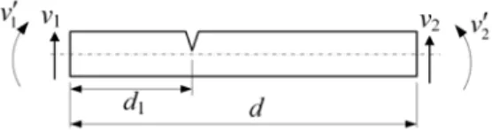
In this study, a finite element model is constituted to represent a cracked beam element of length d and the crack is located at a distance d1 from the left end of the element as shown in Figure 2. The
element is then considered to be split into two segments by the crack. The left and right segments are represented by non-cracked sub elements. The crack represents net ligament effect created by loadings. This effect can be related to the deformation of the net ligament through the compliance expressions (cij) by replacing the net ligament with a fictitious spring connecting both faces of the crack (Yokoyama and Chen, 1998; Ibrahim et al., 2013).
Figure 2: Crack locations in crack element.
The spring effects are introduced to the system by using the local flexibility matrix given by Eq. (9). The cracked element has two nodes with two degrees of freedom in each node. They are denoted as lateral bending displacements( , )v v1 2 and slopes ( , )v v1¢ ¢2 ,
Latin American Journal of Solids and Structures 13 (2016) 175-200
2 3
1 1 2 3 4
1 1
( )
v x a a x a x a x dv
v
dx
= + + +
¢ = (10a)
For d1£ £x d
2 3
2 5 6 7 8
2 2
( )
v x a a x a x a x
dv v
dx
= + + +
¢ = (10b)
The coefficients a of the polynomials can be expressed uniquely in terms of the boundary condi-tions and the local flexibility concept at the crack location. Eventually, the following expressions are obtained for a cracked element:
For lateral bending,
1 1 1 2
2 3 2 4
(0) , (0) ( ) , ( )
v q v q
v d q v d q
¢
= =
¢
= = (11)
At the crack location d1, the flexibility concept requires: For lateral bending:
Continuity of the vertical displacement,
1( )1 2( )1
v d =v d (12a)
Discontinuity of the cross-sectional rotation (slope),
2( )1 1( )1 33 1( )1
v d¢ =v d¢ +c M d (12b)
where
1
1( )1 1 x d
M d =EIv¢¢ = and I denotes the area moment of inertia of the beam cross section.
Continuity of bending moment,
1( )1 2( )1
M d =M d (12c)
Continuity of shear force,
1( )1 2( )1
S d =S d (12d)
By considering Eq. (10) which describes the displacement for the left and right parts of the ele-ment and rearranging Eqs. (11) and (12), the nodal displaceele-ment can be expressed in matrix forms as
{ }
qv = ê úé ùë ûDv{ }
a (13)Latin American Journal of Solids and Structures 13 (2016) 175-200
{ }
1 2 0 0 0 0 3 4 T vq = êéëq q q q ùúû (13a)
{ }
1 2 3 4 5 6 7 8T
a = êéëa a a a a a a a ùúû (13b)
The generalized displacement vector according to local reference coordinates can be expressed as:
q= êéëu1 v1 v1¢ u2 v2 v2¢ùúû (14)
Energy equations should be expressed separately from the crack element and intact elements on the left side of the crack element.
The elastic potential energy U:
For intact elements on the left side of the cracked element,
2 1 0 1 ( ) 2 d L
U EI v dx
æ ö÷
ç ¢¢ ÷ ç
= çç ÷÷ ÷
çè
ò
ø (15a)For the cracked element,
1 1 2 2 1 2 0 1 1 ( ) ( ) 2 2 d d C d
U EI v dx EI v dx
æ ö÷ æ ö÷
ç ¢¢ ÷ ç ¢¢ ÷
ç ÷ ç ÷
= çç ÷÷+ çç ÷÷
ç ÷ ç ÷
è
ò
ø èò
ø (15b)For intact element on the right side of the cracked element,
2 2 0 1 ( ) 2 d R
U EI v dx
æ ö÷
ç ¢¢ ÷
ç
= çç ÷÷ ÷
çè
ò
ø (15c)Similarly, the kinetic energy T of an element of length d in an Euler beam is given as follows for the intact elements on the left side of the cracked element,
2 1 0 1 ( ) 2 d L
T rA v dx
é ù
ê ú
= ê ú
ê ú
ë
ò
û (16a)
For the cracked element,
1 1 2 2 1 2 0 1 1 ( ) ( ) 2 2 d d C d
T rA v dx rA v dx
é ù é ù
ê ú ê ú
= ê ú+ ê ú
ê ú ê ú
ë
ò
û ëò
û (16b)
For intact element on the right side of the cracked element,
2 2 0 1 ( ) 2 d R
T rA v dx
é ù
ê ú
= êê úú
ë
ò
ûLatin American Journal of Solids and Structures 13 (2016) 175-200
4 PROCEDURE FOR DYNAMIC ANALYSIS
For a hinged-hinged cracked beam with elastic supports under the action of a moving load shown in Figure 3, the overall mass and stiffness matrices are obtained by assembling the element matrices. The number of elements used in the finite element vibration analysis is 30.
Figure 3: Cracked beam subjected to a moving load, F(t).
The dynamic response of the cracked beam is calculated by using the procedure described in the Newmark integration method which is widely used in structural dynamics. By using the overall mass [M ], damping [C ] and stiffness [K ] matrices for the beam, the governing equations of the system are written in the matrix form as
{ }
t{ }
t{ } { }
t tM q C q K q F
é ù +é ù +é ù = ê ú ê ú ê ú
ë û ë û ë û (17)
where
{ } { }
,t t
q q and
{ }
tq are the nodal acceleration, velocity and displacement vectors at time t,
respectively.
{ }
tF is the global external excitation vector subjected to the beam at time t. The
nod-al externnod-al excitation vector at time t is constructed using the linear variation assumption of the force when it travels between two adjacent nodes as described by Eq. (18).
{ }
0 0 0 node t i node F F tforce is moving away from the node i t
f
F force is approaching to the node i t t u u ìïï ï -ïï ïïï = íïïï ïï ïïïî
(18)
where F0 denotes the magnitude of the moving load, tnode denotes the time interval to travel
be-tween two nodes and tυis the local time, which has the value between 0 and tnode. If the force is on
the ith node, tυ equals to zero, and if the force is on one of the adjacent nodes, tυ equals to tnode. In
Latin American Journal of Solids and Structures 13 (2016) 175-200
(
)
0 2 1 2 3
4 5 6 7
1 1 1
, , , 1,
2
1, 2 , 1 ,
2
a a a a
t t
t
t
a a a t a t
g
b b b
b
g g g g
b b
= = = =
-D D
D
æD ÷öæ ö÷ ç ÷ç ÷
= - =ççç ÷÷ççç - ÷÷ = D - = D è øè ø
(19)
where t is the time increment used in the numeric analysis and taken as t=T10/20 and T10 is the
10th natural period of the beam. The integration parameters and are selected as 1/4 and 1/2, respectively, in order to obtain a stable solution. The effective stiffness matrix is calculated to per-form the dynamic analyses as
0 1
ef
K K a M a C
é ù=é ùê ú+ é ùê ú+ é ùê ú ê ú ë û ë û ë û
ë û (20)
The effective load vector Fef is calculated for each time step as
F
ef
F
tt
M
a
o
q
t
a
2
q
t
a q
3
t
C a q
1
t
a
4
q
t
a
5
q
t
(21) The nodal displacement, acceleration and velocity responses at time t+t can be obtained by using the following equations
1
ef ef
t t
q
K
F
(22)
q
tt
a
o
q
tt
q
t
a
2
q
t
a q
3
t (23)
q
tt
q
t
a
6
q
t
a
7
q
tt (24)In this study, the effect of damping on the dynamic response of the beam is not taken into con-sideration and the damping matrix [C ] is taken as zero. Moreover, the elastic support is modeled using the linear translation springs located on each node as seen in Figure 3. The linear springs have the effect on the vertical translational degree of freedom and the stiffness of each spring is added to the diagonal terms of the global elastic stiffness matrix. The elastic foundation parameter is used as the ratio between the equivalent spring coefficient of the elastic support and the hinged-hinged beam. support 3 ( ) 48 / eq k Elastic foundation parameter
EI L
= (25)
5 NUMERIC ANALYSIS AND RESULTS
Latin American Journal of Solids and Structures 13 (2016) 175-200
Properties Quantity
Modulus of elasticity, E 69 GPa Mass density, 2700 kg/m3
Cross-section h 5 mm
b 20 mm
Beam length, L 500 mm
Table 1: Properties of the beam.
Figures from 4 to 6 show the effect of crack ratio (a/h) and crack location (L1/L) on the first
three natural frequencies of the cracked beam with different elastic foundation parameters. As can be seen from these figures, as the crack ratio (or depth) increases, the variations of the the natural frequencies become significant. When the crack ratio is between 0 and 0.3, there is no considerable effect of the crack depth and location on the first natural frequency. But, the effects of these pa-rameters towards the higher natural frequencies become evident even in smaller crack ratios. More-over, the crack does not affect the natural frequencies when it is located at the particular points (nodes in mode shapes) of the beam length, since stresses in these points are so small. The maxi-mum reduction occurs in the first, second and third natural frequency values, respectively for un-supported case. These reductions are 8.85%, 8.23% and 7.75%. However, for un-supported case, the maximum reduction occurs in the second, third and first natural frequency values, respectively namely as 7.72%, 7.65% and 4.28%.
Latin American Journal of Solids and Structures 13 (2016) 175-200 Figure 5: The effect of crack ratio and location on the second natural frequency of
cracked beam with elastic support.
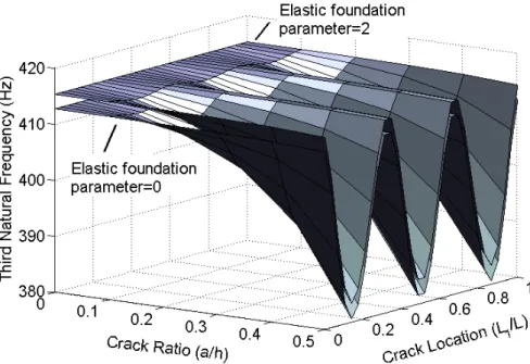
The maximum decreases in the natural frequencies occur when the crack location at the mid-point of the beam (L1/L=0.5) for the first natural frequency, at the L1/L=0.24 and L1/L=0.75 for
the second natural frequency and at the L1/L=0.138, L1/L=0.5 and L1/L=0.86 for the third natural
frequency. It is observed that the crack location is more effective at the higher natural frequencies while the crack ratio increases. As known fact is that when an elastic support or spring is added to the hinged-hinged beam, the natural frequencies increase. As seen in Figures 4, 5 and 6, while the first natural frequency increases significantly with increasing the elastic foundation parameter, this increment is greatly reduced towards the higher natural frequencies. The effects of the crack ratio and location on the natural frequencies are similar to unsupported case.
In this study, the dynamic response of the cracked beam is presented with respect to the non-dimensional load velocity α which is defined as:
1
T a
t
= (26)
where T1 is the first natural period of the beam, and τ is the total time in which the moving load
Latin American Journal of Solids and Structures 13 (2016) 175-200
Figure 6: The effect of crack ratio and location on the third natural frequency of cracked beam with elastic support.
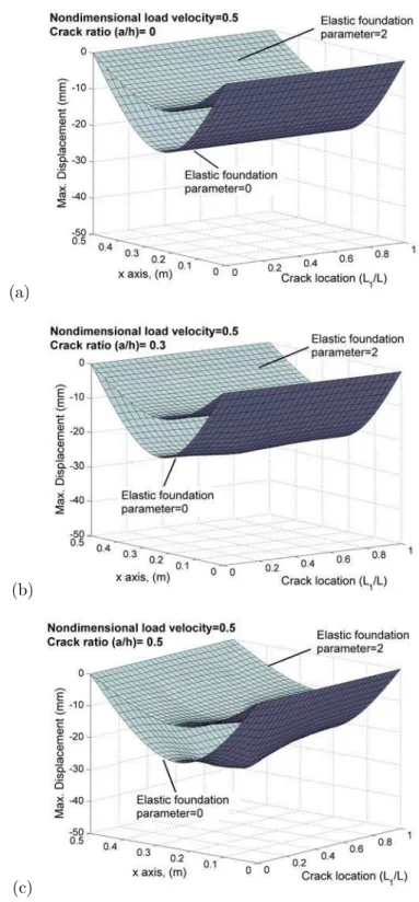
Figures 7-11 present the effects of the elastic foundation parameter, crack ratio and crack loca-tion on the maximum displacement values calculated at the nodes of the cracked beam for different nondimensional load velocities. The dynamic displacement has the maximum value around the mid-point of the beam without being dependent on the nondimensional load velocity, crack ratio and crack location. When the nondimensional load velocity is 2, the maximum displacement is observed at the locations 0.5L and 0.66L for supported case.
Latin American Journal of Solids and Structures 13 (2016) 175-200
(b)
(c)
Figure 7: The effects of elastic foundation parameter, crack ratio and crack location on the maximum displacement at the nodes of the cracked beam for nondimensional load velocity α=0.25.
The displacement decreases as expected when the elastic foundation parameter increases. As the crack ratio increases, considerable increment in the dynamic displacements appear as shown in fig-ures, but this increment is more noticeable when the crack ratio is larger than the value of 0.3 and the crack location is between L1/L=0.2 and L1/L=0.8 . Similar to the natural frequency analysis,
Latin American Journal of Solids and Structures 13 (2016) 175-200
(a)
(b)
(c)
Latin American Journal of Solids and Structures 13 (2016) 175-200
(a)
(b)
(c)
Latin American Journal of Solids and Structures 13 (2016) 175-200
(a)
(b)
(c)
Latin American Journal of Solids and Structures 13 (2016) 175-200
(a)
(b)
(c)
Latin American Journal of Solids and Structures 13 (2016) 175-200
As can be seen from Figures 7-11, it is observed that the dynamic displacement of the beam in-creases with nondimensional load velocity value approaching to 1. However, it dein-creases after non-dimensional load velocity value of 1.5. This case can be distinctly observed when the crack ratio and elastic foundation parameter are equal to 0. Besides, Kiral (2009) have found that the critical nondimensional load velocity, at which the maximum mid-point displacements occur, is 1.2 for a hinged-hinged beam. As seen from Figures 7-11, the maximum displacements along the beam occur symmetrically with respect to the mid-point of the beam until a crack ratio value of 0.3. After this value, this symmetric variation does not appear. As the elastic foundation parameter increases, the pattern of the maximum displacement values shows a difference according to the case without an elastic foundation due to the change in the structural stiffness. This situation can be seen more clearly in Figures 10 (c) and 11 (c) in which the nondimensional load velocity is 1.5 and 2.
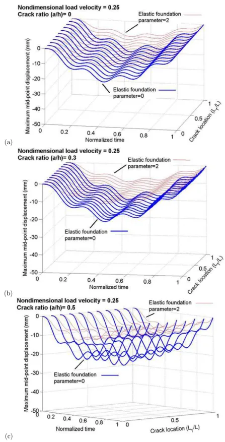
The time-varying maximum displacements of the cracked beam calculated for the beam mid-point are given in 3D graphics in Figures from 12 to 16. Figure 12 shows the dynamic displace-ments of the beam obtained at α=0.25 for different sizes and locations of the crack. The time axis is normalized by dividing the elapsed time by the total load travel time for each case. It is seen from the Figures 12a, 12b and 12c that the dynamic displacements increase apparently as the crack depth increases. Similar to the maximum displacement of the beam analysis, the displacement changes with respect to the crack location (L1/L). These situations are shown in Figures 14 to 16.
At this low load velocity (α=0.25), the maximum mid-point displacements occur when the load is on the beam mid-point. In addition, Figure 12c shows that reduction in the mid-point displace-ments for the case that the crack is near to the mid-point of the beam, is bigger than those ob-tained when the crack is near to the end of the beam. The camel's hump-like displacement pattern shown in Figure 12c is the clear reflection of this result. Figure 12 also shows that the elastic sup-port reduces the dynamic displacements as expected. Figure 13 shows the mid-point dynamic dis-placements of the cracked beam for the nondimensional load velocity α=0.5. For this load velocity, dynamic displacements increase and the time at which the maximum displacements are recorded shifts left. Effect of the crack location on the dynamic displacements is more apparent as seen in Figure 13c. But, the elastic support significantly suppresses the effect of the crack location on the dynamic displacements.
Latin American Journal of Solids and Structures 13 (2016) 175-200
(a)
(b)
(c)
Latin American Journal of Solids and Structures 13 (2016) 175-200
(a)
(b)
(c)
Latin American Journal of Solids and Structures 13 (2016) 175-200
(a)
(b)
(c)
Latin American Journal of Solids and Structures 13 (2016) 175-200
(a)
(b)
(c)
Latin American Journal of Solids and Structures 13 (2016) 175-200
(a)
(b)
(c)
Latin American Journal of Solids and Structures 13 (2016) 175-200
6 CONCLUSIONS
In this study, dynamic displacements of a cracked beam subjected to a concentrated moving load with constant velocity are investigated by using the finite element method. The crack element and its local flexibility are obtained by using the fundamental knowledge of fracture mechanics. The depth and location of the crack and the moving load velocity are used as the parameters of the numerical analysis. Effect of the elastic support, which is modelled by linear springs, on the dynam-ic response of the cracked beam is also investigated. Based on the numerdynam-ical results obtained in this study, the following conclusions are drawn,
The natural frequencies of the cracked beam get smaller as the crack depth increases. Moreo-ver, the crack does not affect the natural frequencies when it is located at the particular points (nodes in mode shapes) of the beam length.
Reduction in the natural frequencies induced by the increasing crack size is more apparent at the lower natural modes without the elastic supports.
Effect of the elastic support on the natural frequencies of the cracked beam reduces at the higher vibration modes.
The crack, which is located near to the middle of the beam, has more influence on the in-crease in the dynamic displacement amplitudes.
The amplitude of the dynamic displacements increases as the crack ratio increases for all load velocities. The elastic support helps to reduce the dynamic displacements of the beam. When the crack ratio is 0.5, the pattern of the maximum displacement values of the beam
changes significantly with respect to the crack location.
The maximum displacements along the beam occur symmetrically with respect to the mid-point of the beam until a crack ratio value of 0.3. After this value, this symmetric variation does not appear. As the elastic foundation parameter increases, the pattern of the maxi-mum displacement values shows a difference according to the case without an elastic foun-dation.
For with or without the elastic support case, the displacement pattern loses its symmetry as the load velocity increases.
Velocity of the moving load has considerable influence on both the mid-point dynamic dis-placements and their occurrence time.
REFERENCES
Chang, T.P., Liu, Y.N. (1996). Dynamic finite element analysis of a nonlinear beam subjected to a moving load. International Journal of Solids and Structures 33(12): 1673-1688.
Clough, R.W., Penzien, J. (1993). Dynamics of Structures. New York: McGraw-Hill.
Dabney, J., Harman, T.L. (1999). Advanced Engineering Mathematics with MATLAB. USA: Brooks/Cole Publish-ing Company.
Esen, I. (2015). A new FEM procedure for transverse and longitudinal vibration analysis of thin rectangular plates subjected to a variable velocity moving load along an arbitrary trajectory. Latin American Journal of Solids and Structures 12:808-830.
Latin American Journal of Solids and Structures 13 (2016) 175-200
Goren Kıral, B., Kıral, Z. (2009). Effect of elastic foundation on the dynamic response of laminated composite beams to moving loads. Journal of Reinforced Plastics and Composites 28(8): 913-935.
Gounaris, G., Dimarogonas, A. (1988). A finite element of a cracked prismatic beam for structural analysis. Com-puters & Structures 28(3): 309-313.
Hino, J., Yoshimura, T., Ananthanarayana, N. (1985). Vibration analysis of non-linear beams subjected to a moving load using the finite element method. Journal of Sound and Vibration 100(4): 477-491.
Ibrahim, A.M., Ozturk, H., Sabuncu, M. (2013). Vibration analysis of cracked frame structures. Structural Engineer-ing and Mechanics 45(1): 33-52.
Karaagac, C., Ozturk, H., Sabuncu, M. (2009). Free vibration and lateral buckling of a cantilever slender beam with an edge crack: Experimental and numerical studies. Journal of Sound and Vibration 326(1-2): 235-250.
Kargarnovin, M.H., Ahmadian, M.T., Talookolaei, R.A.J. (2012). Dynamics of a delaminated timoshenko beam subjected to a moving oscillatory mass. Mechanics Based Design of Structures and Machines 40: 218–240.
Kidarsa, A., Scott, M.H., Higgins, C.C. (2008). Analysis of moving loads using force-based finite elements. Finite Elements in Analysis and Design 44: 214-224.
Kıral, Z. (2009). Damped response of symmetric laminated composite beams to moving load with different boundary conditions. Journal of Reinforced Plastics and Composites 28(20): 2511-2526.
Kıral, Z., Gören Kıral, B. (2008). Dynamic analysis of a symmetric laminated composite beam subjected to a moving load with constant velocity. Journal of Reinforced Plastics and Composites 27(1): 19-32.
Law, S.S., Zhu, X.Q. (2000). Study on different beam models in moving force identification. Journal of Sound and Vibration 234(4): 661–679.
Law, S.S., Zhu, X.Q. (2006). Vibration of a beam with a breathing crack subject to moving mass, In: Liu, G.R., Tan, V.B.C., Han, X. (eds) Computational Methods. Netherlands: Springer, 1963–1968.
Lee, H.P., Ng, T.Y. (1994). Dynamic response of a to a moving load cracked beam subject. Acta Mechanica 106: 221-230.
Lin, H.P., Chang, S.C. (2006). Forced responses of cracked cantilever beams subjected to a concentrated moving load. International Journal of Mechanical Sciences 48: 1456-1463.
Lin, Y.H., Trethewey, M.W. (1990). Finite element analysis of elastic beams subjected to moving dynamic loads. Journal of Sound and Vibration 136 (2): 323-342.
Mahmoud, M.A., Abou Zaid, M.A. (2002). Dynamic response of a beam with a crack subject to a moving mass. Journal of Sound and Vibration 256(4): 591-603.
Olsson, M. (1991). On the fundamental moving load problem. Journal of Sound and Vibration 145(2): 299–307. Ostachowicz, W.M., Krawczuk, M. (1990). Vibration analysis of a cracked beam. Computers & Structures 36(2): 245-250.
Rao, G.W. (2000). Linear dynamics of an elastic beam under moving loads. Journal of Vibration and Acoustics 122(3): 281–289.
Shen, M.H.H., Pierre, C. (1994). Free vibrations of beams with a single-edge crack. Journal of Sound and Vibration 170(2): 237-259.
Thambiratnam, D., Zhuge, Y. (1996). Dynamic analysis of beams on an elastic foundation subjected to moving loads. Journal of Sound and Vibration 198(2): 149-169.
Wang, R.T. (1997). Vibration of multi-span Timoshenko beams to a moving force. Journal of Sound and Vibration 207(5): 731–742.
Latin American Journal of Solids and Structures 13 (2016) 175-200
Yokoyama, T., Chen, M.C. (1998). Vibration analysis of edge-cracked beams using a line-spring model. Engineering Fracture Mechanics 59(3): 403-409.