Issues on beam-plasma instability - early simulations focusing
on the development of a compact neutron generator
(Considera¸c˜oes sobre instabilidade feixe-plasma - simula¸c˜oes iniciais centradas no desenvolvimentode um gerador compacto de nˆeutrons)
Wagner Leite Araujo
1and Tarcisio Passos Ribeiro de Campos
Departamento de Engenharia Nuclear, Universidade Federal de Minas Gerais, Belo Horizonte, MG, Brasil Recebido em 17/9/2009; Aceito em 27/10/2009; Publicado em 15/2/2011
The first issue on compact neutron generator design is the definition of the plasma generation process follow-ing the analysis of the physical plasma state. The plasma features and the nuclear reactions of fusion involved in the operation of the generator, deuterium-deuterium or deuterium-tritium, as well as the system which deter-mines the trajectories of the particles and the target, are decisive to predict the neutron yield from the generator. Hence, the plasma behavior analysis under established conditions becomes an important evidence. This analysis may be done by means of plasma simulation models. Particle simulation of plasmas, employed since 1960s, provides a picture of the general plasma characteristics. Plasma physics is determined in most cases by simple equations, i.e.equations of motion of electrons, ions and neutrals atoms including the effect of collisions and self-consistent electric and magnetic fields. Computer simulation of plasmas comprises two general areas based on kinetic and fluid. While fluids simulation proceeds by solving numerically the magnetohydrodynamic (MHD) equations, assuming approximate transport coefficients, kinetic simulation considers more detailed models of plasma involving particle interactions through the electromagnetic fields. This article is focused on the simula-tion and analysis of injected beam into a steady state and periodic plasma. The applied calculasimula-tion model, for this simulation purpose, is referring to an electrostatic one dimension code, based on kinetic simulation, which simulates periodic plasmas illustrating various fundamental considerations of plasma simulation and make it useful in simulations of the beam optic system for neutron generators. The main goal of this research is explore the PIC code reviewing the computational and physics theory necessary to build the structure of the elementary principles intending to introduce concepts of plasma physics and the computational theory. Moreover, founda-tions of plasma analysis for neutron generators will be stated.
Keywords: plasma simulation, pic code, compact neutron generators.
A primeira considera¸c˜ao no projeto de um gerador compacto de nˆeutrons ´e a defini¸c˜ao do processo de produ¸c˜ao de plasma seguido da defini¸c˜ao da an´alise do estado f´ısico desse plasma. As caracter´ısticas do plasma e as rea¸c˜oes nucleares de fus˜ao envolvidas na opera¸c˜ao do gerador, deut´erio-deut´erio ou deut´erio-tr´ıtio, bem como o sistema que determina as trajet´orias das part´ıculas e o alvo, s˜ao decisivos para estimar o rendimento de nˆeutrons do gerador. Dessa forma, a an´alise do comportamento do plasma sob condi¸c˜oes estabelecidas se torna uma eviden-cia importante. Essa an´alise pode ser feita por modelos de simula¸c˜ao de plasma. A simula¸c˜ao de part´ıculas de plasma, empregada desde a d´ecada de 1960, fornece uma descri¸c˜ao das caracter´ısticas gerais do plasma. A f´ısica de plasma ´e determinada, na maioria dos casos, por equa¸c˜oes simples, isto ´e, equa¸c˜oes de movimento de el´etrons, ´ıons e ´atomos neutros incluindo o efeito das colis˜oes e campos el´etricos e magn´eticos auto-consistentes. As simu-la¸c˜oes computacionais de plasma compreendem duas ´areas gerais baseadas em cin´etica e an´alise fluidodinˆamica. Enquanto a simula¸c˜ao em dinˆamica de fluidos se procede por meio da resolu¸c˜ao num´erica de equa¸c˜oes da mag-netohidrodinˆamica (MHD), assumindo coeficientes de transporte; a simula¸c˜ao cin´etica considera modelos mais detalhados de plasma, envolvendo intera¸c˜oes das part´ıculas com os campos eletromagn´eticos. Esse artigo ´e fo-cado na simula¸c˜ao e an´alise de um feixe de el´etrons injetado dentro de um plasma estacion´ario e peri´odico. O modelo de c´alculo empregado, para este prop´osito de simula¸c˜ao, ´e referente a um c´odigo unidimensional, baseado em simula¸c˜ao cin´etica, que simula plasmas peri´odicos ilustrando v´arias considera¸c˜oes fundamentais em simula¸c˜ao de plasma e se torna ´util em simula¸c˜oes do sistema da ´optica de feixe para geradores de nˆeutrons. O objetivo principal desse estudo ´e explorar o c´odigo PIC revisando a teoria f´ısica e computacional necess´aria para construir a estrutura dos princ´ıpios elementares com inten¸c˜ao de introduzir conceitos da teoria f´ısica de plasma e da teoria computacional. Al´em disso, os fundamentos da an´alise de plasma para geradores de nˆeutrons ser˜ao declarados.
Palavras-chave: simula¸c˜ao de plasma, c´odigo pic, gerador de nˆeutrons compacto.
1E-mail: wagnerleite@ymail.com.
1.
Introduction
Plasma is the fourth state of matter, consisting of free electrons, ions and atoms or molecules. It is charac-terized by its collective behavior. Plasmas are many-particle ensembles; the charged many-particles are coupled by electric and magnetic self-generated and self-consistent fields [1]. Ionization, which produces the plasma in most devices, can be introduced by extreme heat, pres-sure, electrostatic and magnetostatic fields or through electromagnetic discharges as commonly designed in a modern compact neutron generator [2].
Compact neutron generators are devices that con-tain linear accelerators that produce neutrons based on fusion of hydrogen isotopes. Fusion reactions take place in those devices via acceleration of deuterium or tritium ions, or the mixture of the both isotopes, towards a hy-brid target of metal also composed of deuterium, tri-tium or a mixture of two. Neutron sources that use reactions DD (deuterium deuterium), DT (deuterium -tritium) offer a surprising technology, because they can supply a neutron beam of high flux from a small source, pulsed-type electronically collimated. Thus, neutron generators based on those reactions can be used as a powerful tool in several fields in which there is demand of a small beam of neutrons [3]. The reaction D + D → 3He + n + 3.3 MeV was first to provide mono-energetic fast neutrons. However, the most applied fu-sion reaction is from deuterium-tritium. This fufu-sion re-action is the easiest to perform and also the most used in neutron generators. Reaction T + D → 4He + n + 17.6 MeV occurs with more probability because the neutron in excess on the tritium nuclide increases the size of nucleus and therefore the cross section of fusion reaction.
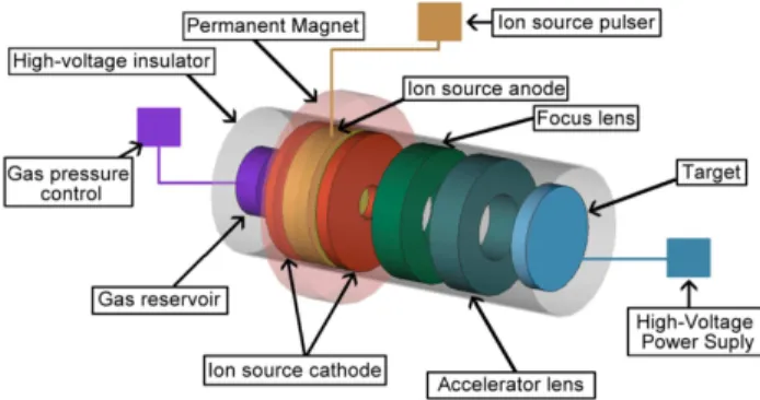
The basic project of a compact neutron generator includes the design of a modern and compact acceler-ator, including a gas-control reservoir, plasma and ion source to generate and put the ions in a beam shape, re-spectively; and a target constituted of material loaded of hydride and metal. A schematic design of a neutron generator based in a work of Worpole [4] is shown in Fig. 1. A subject of study on the plasma behavior for neutron generators is the optimization of the plasma generator device to produce higher charge states and a higher number of particles. The ion source produces the ions created from the plasma through an electrode system, subsequently the ions of deuterium or tritium are accelerated toward a metal target loaded with deu-terium, tritium or mixture of both, where occur the neutron generation reactions. Plasma is produced in-side an ion source and its proprieties and characteristics determine to a large extent the kind of ion beam that is produced [5]. In according to the design of the neu-tron generator tube, it is necessary to collimate the ion beam, once the ions have same charge. The system to collimate the beam is not required since the length of
the transport system is very small; in this case the ion beam is sufficiently nondiverging [6].
Figure 1 - Illustration of a neutron generator with a Penning ion source.
A method to produce plasma in neutron generator devices is using electrostatic and magnetostatic fields. For example, Penning ions sources [7] use electrosta-tic fields to separate the nuclei of deuterium or tritium of its electron. The electrons are accelerated into the plasma chamber by means of the electrostatic fields gen-erated by a cathode and an anode to produce more ion-ization helping to sustain the plasma. Analysis done here give an idea of the physical quantities as product of this interaction.
A beam of electrons interacting with a plasma will be simulated with the goal of describing the PIC code used in the beam optics simulations of particle accelerators, and in this article in our plasma simulation -inside of an ion source. The idea of this code will be depicted.
Problems found in plasma physics encourage the planning of computational simulations that also con-tribute to the development of a plasma theory. Com-puter simulations of plasma became a great physical planning tool to provide prognosis of performance in the physical plasma applications such as neutron gen-erator as well as fusion reactors and other equipments. Based on evaluation of the plasma behavior under particular conditions defined by electron beam injected into a steady state plasma, a variety of concepts will be examined. The investigation will be done on a weak beam, generated in space and time in terms of electric field, electric potential, kinetic energy, field energy and total energy (kinetic plus energy stored in electrostatic field). In the following sections, the required concepts of the basic theory of plasma computer simulations and likewise the necessary mathematical and physical prin-ciples of the plasma physics will be discussed.
2.
Preliminary concepts
simulate accurately the collective behavior of real plas-mas.
2.1. The electrostatic model
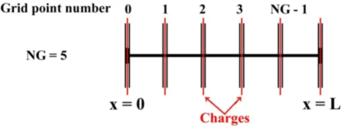
The model predicts the behavior of charged parti-cles motion due to forces of their own and applied fields. Physical examination is rooted in the fact that a charged particle produces a field - electric field anyway and magnetic field if it is in motion, a force is gener-ated due to the interaction of the field(s) with other particles, this force determines the equation of motion. The fields are calculated through Maxwell equations by knowing the positions of the particles and their ve-locities. The forces on the particles are found using the electric and magnetic fields in the Newton-Lorentz equation. Initially the fields are calculated from the first charge and current densities, then the particles are moved to small distances and subsequently the fields are recalculated due to new positions and velocities which the particles acquire; this process is repeated for many time steps. The one dimensional geometry model, treated here, is shown in Fig. 2.
Figure 2 - Geometry of the one-dimensional simulation box con-sisting of a many sheet charges, with self and applied electrical field along the axisx. The first grid point is placed atx= 0.
2.2. Mathematical description and considera-tions
The model employed here is the Particle in Cell (PIC) [8], originated from the work of J.M. Dawson [9-11] in the late fifties. In this model, the plasma is rep-resented by macroparticles, since each particle used in the simulation represents thousands of particles of a real experiment. The macroparticles are used to repre-sent the system and thus include its kinetic behavior. PIC code is able to integrate in time the trajectories of a huge numbers of charged particles in their self-consistent electrostatic fields. The PIC system assumes that particles do not interact with each other directly, but through the fields which they produce according to the Maxwell’s equations. Particles can be located anywhere in space; nevertheless, the field quantities are calculated on a fixed grid.
Computational cycle starts with the knowledge of the initial particle position xi from which the charge densityρ(xn) is found at the grid pointsxn by interpo-lation
ρ(xn) = ΣiqiS(xn−xi), (1) in whichSis the particle shape function which replaces point charges with a finite size charge cloud to reduce close range collision effects. The particle charge is qi
with center xi [12]. Next, the electric field E(xn) is found at the grid points by solving Poisson’s Equation
∇E(xn) =−∇2φ=ρ(xn)/ε, (2) using the Fast Fourier Transform [13]. This electric field is then used to calculate the force on each particle whose trajectories are updated by integrating Newton’s Law,
dυi/dt=E(xi)qi/mi (3)
dxi/dt=υi (4)
The velocity and position of each particle are advanced in time using a time centered leap-frog scheme [14]
υi(t+ ∆t/2) =υi(t−∆t/2) + [Fi(t)/mi]∆t, (5)
xi(t+ ∆t) =xi(t) +υi(t−∆t/2)∆t. (6) This cycle then is repeated for the duration of the simulation. Diagnoses are computed along the way and all lengths are normalized to the grid spacing. These lengths are related back to physical lengths later.
PIC code applied in simulations of charged parti-cle dynamics or beam optics of the transport system in particle accelerators is well discussed in the litera-ture [15] and used in various software as CST Particle Studio [16].
2.3. Computational cycle: brief remarks
At each time step, the algorithms solve the field for the particles and then move it. This cycle is illustrated in Fig. 3.
Figure 3 - Characteristic cycle in a particle simulation program for one step time. The particles indices arei= 1, 2, ... , NP; the indices of the mathematical grid,i.e.the discretization of space, arej. The time follows in clockwise rotation.
Numbers of time steps are dictated, thus the computer runs printing out different diagnoses in form of snap-shots at particular times, as kinetic energy vs. time, potential or field distributions, for example.
3.
Instability analysis and
considera-tions on the simulation
The Eq. (7) shows the relation of dispersion used by the code for this simulation
1−ωp/ω2 2−ωb/(ω−k·υ0)2= 0. (7) Usually the injected beam densityηbis much smaller than the plasma densityηp, such thatω2
b << ωp2, where ωb is the beam frequency and ωp is the plasma fre-quency. This hypothesis is the vital principle of the called beam model [17]. The interactions in weak-beam model are of type electron-electron with a static neutralizing ion background, that ismi/me→infinity, wheremi andme are the ion and the electron mass re-spectively. The plasma frequencyωp is prevailing and the interesting wave numbers are close to k = ωp/υ0,
whereυ0 is the electron beam velocity.
The instability inspected here is due to the interac-tion of plasma with a weak (by choosingω2
b/ωp2= 0.001)
beam, passing through it. The crucial purpose of this simulation is the understanding of general plasma be-havior under the described circumstances, without in-terest in specific data in the graphs. Then, the more important characteristic that will be analyzed is the general behavior of the curves.
Withω2
b/ωp2<<1, particles of the plasma could be
considered as a linearized fluid or assumed by a linear susceptibility. One essential observation is if the plasma frequency presents a linear response to the beam, there is freedom of choose a small value forq/mto make sure that the plasma keeps linear [18]. This permits to use a small number of plasma particles, as few as one per cell. The diagnosis studied here is obtained from XES1 one dimensional plasma simulation code [19]. Simulation results will be shown in all graphs at the same time in the end of simulation, 251494µs, by means of the char-acteristics of interaction of the cold plasma and cool electron beam, which will be presented in diagnoses.
A cold plasma is classically characterized by the sit-uation where there is a low degree of ionization. Rig-orously, a cold plasma is one in which ionized electrons do not have sufficient energy to escape from the influ-ence of its corresponding ion, and thus do not exhibit random motion [20]. A cool electron beam is drifting through cold unperturbed plasma. The low temper-ature of the beam avoids the non-physical cold beam instability, so the only phenomenon is the growth of the physical beam plasma instability [21]. The distri-bution function of the cool electrons was described by Gyergyek and `Eer`eek [22].
The parameters used in the simulation jointly with its values are listed in Table 1. Length of the grid is referring to stage of the computational cycle. Number of particles of the plasma refers to the particles that interact with the beam, i.e.electrons.
Table 1 - Parameters and Input data of simulation.
Description Input value
Number of species 2
Time step 0.1
Total number of steps 4000 Number of grid points 1000 Length of the grid 2π
Number of particles of the beam 512 Number of particles of the plasma 1024 Velocity of the plasma electrons 0 Drift velocity of the electrons in the beam
inxdirection
1.0
4.
Simulation results
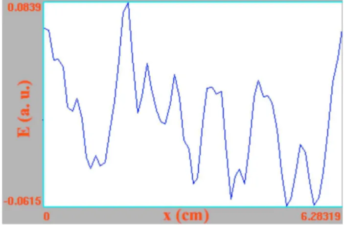
Figure 4 shows the electric fieldvs. position at a specific time. The electric field is smoother than the density of charge, since the spatial integral of the charge density is the electric field. XES1 code uses the electric field to determine the electrostatic force on particles in the mover [23]. The electric field observed in the diagno-sis is periodic, as it should be according to theoretical model proposed.
Figure 4 - Electric fieldE (arbitrary units)vs. positionx(cm)
along the grid. The positions are points situated on the grid.
Figure 5 - Electric potential P (arbitrary units)vs. positionx
(cm) along the grid.
Figure 6 shows the time evolution of field energy (FE). One can see that the FE oscillates substantially in time, as predictable by exceeding variation observed in electric field in position (Fig. 4) and time (while the simulation is running). The mean behavior of FE does not vary appreciably.
Diagnoses of kinetic energy (KE) are displayed in Fig. 7, these analysis are made as a function of the time history of the total kinetic energy for all species.
Figure 6 - Field energy FE (arbitrary units) in function of time
t(µs).
Figure 7 - Kinetic energy KE (arbitrary units) in function of time
t(µs). Blue line represents the sum of electron beam kinetic en-ergy (red line) and plasma kinetic enen-ergy (black line).
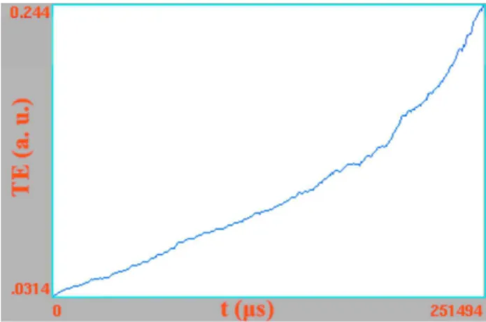
Total energy (TE) is evaluated in Fig. 8. This diag-nostic displays the time history of the total energy of all species, plasma and beam;i.e.total energy = kinetic + field energies. This history is a semi-log plot, calculated from log (TEi) = log (KEi +FEi). The total energy of a given simulation should be conserved. As showed in Fig. 7, the total energy is certainly an increasing func-tion in time, since the plasma state is being continually disturbed by the beam, and the total kinetic energy is likewise an increasing function in time.
Figure 8 - Total energy TE (arbitrary units) in function of time
t(µs).
An interest reader can download the code and per-form by himself new simulations, experimenting with parameters. XES1 is a free software and can be down-loaded in Berkeley web site indicated in Ref. [19]. A manual is available in Ref. [23].
5.
Conclusion
Acknowledgments
The authors are thankful to CNPq - Conselho Nacional de Desenvolvimento Cient´ıfico e Tecnol´ogico, due to the scholarship and the financial support by CNPq process n. 134484/2009-6. We are grateful to PTSG research group due to the XES1 code.
References
[1] A. Dinklage, T. Klinger, G. Marx and L. Schweikhard, Plasma Physics: Confinement, Transport and Collec-tive Effects (Springer, Berlin, 2005).
[2] Y. Wu, J.P. Hurley, Q. Ji, J. Kwan and K.N. Leung, in: AIP Conference Proceedings(Fort Worth, 2009), v. 1099, p. 614.
[3] Compact accelerator neutron generator:
(2010).
[4] I. WORPOLE Schematic Design of a Sealed-Tube Neutron Generator with a Penning Ion Source: (2010).
[5] I. G. Brown, The Physics and Technology of Ions Sources (Wiley-VCH, Berlin, 2004).
[6] K.N. Leung, T.P. Lou and J. Reijonen, US Patent 7342988 B2, (2008).
[7] B.K. Das and A. Shyam, Review of Scientific Instru-ments79, 123305 (2008).
[8] M.M. Woolfson and M.S. Woolfson, Mathematics for Physics (Oxford University Press, Oxford, 2006).
[9] J.M. Dawson and A.T. Lin,Particle Simulation, Hand-book of Plasma Physics (Elsevier Science Publishers, Amsterdam, 1984), v. 2.
[10] J.M. Dawson, Reviews of Modern Physics 55, 403 (1983).
[11] R. Hockney and J. Eastwood, Computer Simulation Using Particles (McGraw-Hill, New York, 1981).
[12] T. Tajima,Computational Plasma Physics: With Ap-plication to Fusion and Astrophysics(Westview Press, Boulder, 1989).
[13] J.F. James,A Student’s Guide to Fourier Transforms: With Applications in Physics and Engineering (Cam-bridge University Press, Cam(Cam-bridge, 2002).
[14] R.M.M. Mattheij,Partial Differential Equations: Mod-eling, Analysis, Computation (Siam Monographs on Mathematical Modeling and Computation) (Society for Industrial & Applied Mathematics, Philadelphia, 2005).
[15] CTS SUITE: Charged Particle Simulation:
(2010).
[16] S. Humphries, Charged Particles Beams:
(2010).
[17] J. B¨uchne, C. Dum and M. Scholer,Space Plasma Sim-ulation(Springer-Verlag, Berlin, 2003).
[18] C.K. Birdsall and A.B. Langdon, Plasma Physics via Computer Simulation (Taylor & Francis, Boca Raton, 1991).
[19] 9 XES1 Code:
(2010).
[20] Plasma Dictionary: Cold Plasma:
(2010).
[21] The Plasma Theory and Simulation Group:
(2010).
[22] T. Gyergyek and M. `Eer`eek, Czechoslovak Journal of Physics54, 431 (2004).
[23] Particle simulations of 1-D Vlasov Problems: ES1
Manual: