An interview with
How to cite this interview: Moon W. Interview. Dental Press J Orthod. 2013 May-June;18(3):12-28. Submitted: February 14, 2013 - Revised and accepted: March 7, 2013
» Patients displayed in this interview previously approved the use of their facial and intraoral photographs.
Won Moon
All in life have a positive side. In 2010, I was studying for my Doctorate in Orthodontics in UNESP-Araquara, Brazil, when for some personal reasons I had to drop my academic activities and return to Salvador city for a while. Luckily or by divine providence I received a great git: The opportunity to meet Dr. Won Moon while he was vis-iting Brazil to present a lecture in the specialization course in Orthodontics at the Federal University of Bahia. It was admiration and friendship at irst sight. A second opportunity to enjoy the contact with Won occurred in 2011, when I was taking part of my sandwich PhD at UCLA. Perceiving his qualities more closely became a motivation for new learnings. Won is a role model teacher and this is exempliied by the many tributes received by his students. His clinical aptitude is striking! In various challenging circumstances I have heard from his residents the following: “Cases like that only Dr. Moon handles...”. There is no need for long descriptions concerning the excellence of his career as an international lecturer. Ater he has visited the most important centers of Orthodontics worldwide you all will be able to appreciate this aptitude by your own! I did not take so long to notice that his qualities go beyond the professional sphere. Despite being blessed for having a very special family, he still manages his time for practic-ing radical sports such as climbpractic-ing and mountaineerpractic-ing. Always accompanied by his wife Miran and his daughter Crystal, there is no lack of stories of trips around the world. It is clear the complicity of a marriage that began in their adolescence! Given the proper introduction of our distinguished interviewee, I also give my cordial thanks to the friends Sergei Rabelo, Richard Kulbersh, Greg Huang and Barry Briss, for accepting the invitation to actively participate of this interview. I also thank to Dental Press for the granted honor to conduct this experience. I wish all the readers a moment as pleasant and rich as the scientiic path that led us to this interview.
André Wilson Machado » Program director, UCLA School of Dentistry, Section of Orthodontics.
» Director, International Afairs, UCLA School of Dentistry, Section of Orthodontics. » Visiting professor, Samsung Medical Center, Seoul, Korea.
» Diplomate of American Board of Orthodontics (ABO).
» Reviewer, The Angle Orthodontist and Dental Press Journal of Orthodontics. » UCLA School of Dentistry, Section of Orthodontics, certiicate in Orthodontics, 1991. » UCLA School of Dentistry, Section of Oral Biology, MS, 1991.
Could you please provide us some of your dental and orthodontic background?
I grew up in Southern California since 1976, and I initially pursued my education in Mathematics at a local university, UC Irvine (UCI). Ater earning a Bachelor of Science (BS) degree in Mathematics, I changed my career path. I let home for the irst time, and I pursued a degree in Doctor of Dental Medicine (DMD) from Harvard School of Dental Medicine (HSDM) in Bos-ton. Ater acquiring a dental license from the North-eastern Regional Dental Board during my last year in dental school, I volunteered as a Peace Corps member and helped building a dental clinic in the city of Above Rocks in Jamaica. This project came to a halt because of Hurricane Gilbert, which caused historical destruc-tion. Ater an early return from Jamaica, I participated in the Licensed Practitioners Clinic at HSDM as a gen-eral dentist before moving back to California in 1989 for a post-doctoral orthodontic residency program at the UCLA School of Dentistry. While pursuing orth-odontic education, I also entered the Master of Science (MS) program in Oral Biology at UCLA. During my dental and orthodontic education, my interest in clinical research proliferated, and I successfully produced and defended three theses.
Since graduation in 1991, I worked at a private orth-odontic clinic in the suburbs of the Los Angeles met-ropolitan area. In 2002, I became a Diplomat of the American Board of Orthodontics. In 2003, I joined the UCLA School of Dentistry, Section of Orthodontics, as a faculty member. Since then, I have served UCLA as the Program Director for Combined Pedo-Ortho Residency Program, Director of Advanced Continu-ing Education, Director of International Afairs, Clinic Director for the Section of Orthodontics, and Direc-tor for PrecepDirec-torship Program. During that time, I also served as the Program Director and Assistant Director for the Southern Region, Paciic Coast Society of Or-thodontists (PCSO). In 2012, I decided to phase out the private clinic ater 21 years of orthodontic practice and join UCLA as a full-time professor. I was appointed as the Program Director for the orthodontic residency program at UCLA, and I also hold the position as the Director of International Afairs.
I am currently involved in various research topics, and they include the Accelerated Tooth Movement, Genome-wide Association Study of Craniofacial
Phe-notypes, Finite Element Model Study, 3-D Image Analysis, and Micro-Implant Study. As you can easily see, it is evident that my mathematics background plays a major part of my research area.
What orthodontic technique do you use in your practice? What is the UCLA’s teaching philosophy?
Since Dr. Edward Angle developed the edgewise technique in modern orthodontics, we have gone through a number of facelifts in our treatment
phi-losophy: extraction versus non-extraction,1 growth
modification versus surgical orthodontics,2 headgear
versus functional appliance,2 centric occlusion
ver-sus centric relation verver-sus neuro-muscular bite,3,4
etc. We can easily find numerous research findings arguing back and forth claiming the superiority of one philosophy over another through many decades, which only proves that there are many different ways of providing orthodontic treatment with satisfactory results. The advent of new tools and appliances such as micro-implants, clear-aligners, self-ligating brack-ets, and CBCT images only adds fuel to the fire. Tra-ditionalists continue to claim that the fundamentals of orthodontic biomechanics cannot be changed, whereas the more progressive practitioners routinely defy old tradition. As an advanced institution of ed-ucation that should respect evidence-based science, but also has an obligation to nurture novel concepts, where do we stand? We are definitely in the busi-ness of teaching the evidence bases of orthodontics; however, we should also put just as much effort in the evidence building. Without those pioneers in our profession, we will not be able to progress.
As you can imagine, this is a daunting task. It is hard enough to teach one technique, not to mention deal with all the above. Fortunately, we are able to recruit the best of the brightest students each year. We put them through extremely rigorous curriculum with enormous amount of resources at UCLA. In simple terms, we throw ev-erything at these incredibly smart individuals, and see what sticks. At the end of their residency, each student will have his/her own brand of orthodontic technique that works the best for him/her. This teaching philosophy has worked very well for us, and we continue to produce highly competent orthodontists every year.
Diagnosis is a vital step for the success in ortho-dontics. What is your opinion on the role of 2-D conventional Cephalometrics in contemporary orthodontic diagnosis?
Dr. B. H. Broadbent’s contribution in orthodontics
cannot be measured.5 He brought objectivity into our
diagnosis by introducing cephalometric images. Since then, many have developed cephalometric analyses to aid in diagnosis, and they have propelled the level of mod-ern orthodontics. However, these measurement systems were largely limited to the simple linear measurements comprised of angles and distances. Although they have established the norm and gave us baseline information, these linear measurements have inherent shortcomings. The linear measurements are adequate in measuring regular structures such as desks and table tops, but they are severely inadequate in measuring irregular structures such as the human skull. The word linear comes from the Latin word linearis, which means resembling a line.
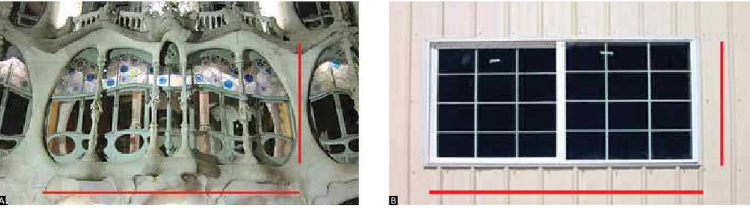
The human morphology is far from resembling a line. Thus, nonlinear equations and functions are of interest to engineers, physicists, and mathematicians because they can be used to represent many natural phenomena and irregular structures. When measuring from point A to point B, the information between these two points is lost with a linear measurement system (Fig 1). In this illustra-tion, two buildings with very diferent morphologies will have similar measurement values when we use the linear measurements. This type of function should not be ap-plied in analyzing the morphology of irregular structures.
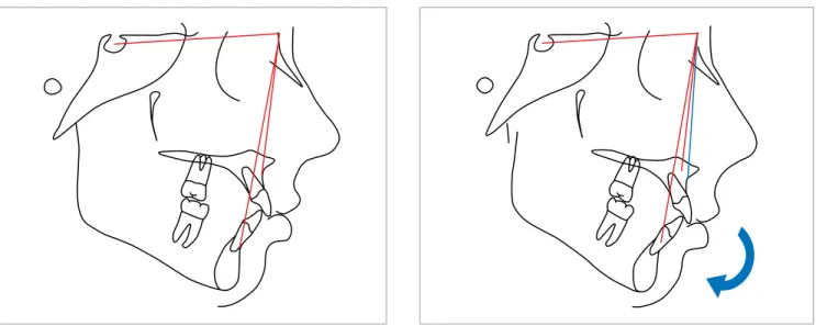
Moreover, linear measurements oten ignore spatial relationships. Figures 2 to 5 illustrate some of the many problems we face using cephalometric analysis that many of us are accustomed to. These problems arise because the reference points, such as nasion, sella,
or-bital, basion, and PT points are highly variable in space.6
In truth, cephalometric analyses such as in Steiner and Ricketts are 1-D analyses applied to 2-D images ex-tracted from 3-D structures. The 2-D image requires a 2-D analysis for adequate quantiication.
During my orthodontic residency at UCLA (1989-1991) we explored the possibility of developing a true 2-D analysis utilizing the Elliptical Fourier’s
Descrip-tor (EFD).7 By utilizing this mathematical equation, we
can describe any irregular curved line in a 2-D space. Figure 6 illustrates the application of this approach to a lateral cephalogram. This is a true 2-D analysis that ac-counts for spatial relationships, and it also is completely quantiiable since the outline of the skull is described by a mathematical equation. That means we are able to generate a graphic illustration of the norm by
calcu-Figure 1 - The window on A was designed by Antoni Gaudi, and it has similar linear dimension to the modern building window on B; however, they do not resemble each other morphologically.
lating an equation that represents an average of many individual equations. Numbers are not necessary, and the superimposed images of the norm and a patient can illustrate the discrepancies between them in any given point that lies on the outline of the skull. This approach was largely ignored by orthodontists because of a lack of desire to learn the new method of evaluating cranial structure; however, it had more impact in the ield of
anthropology.8 I have learned that it is hard to change
the minds of traditionalists, especially something as sa-cred as cephalometric numbers. The IMPA of 90 de-grees was etched in everyone’s brain back in 1991.
Based on these problems listed before regarding the conventional cephalometric analyses, how do we deal with the 3-D images in orthodontics?
It took twenty years for us to inally realize to a full scale how deicient conventional cephalometric analy-ses were. With the advent of CBCT, we faced more complex problems in quantifying 3-D structures. Many investigators are still utilizing the linear measurements to describe a 3-D human skull, applying 1-D
measure-ment system to irregular 3-D images.9 Some compress
these 3-D structures to 2-D images, and apply conven-tional 1-D analysis. This is analogous to playing a high
quality CD digital music through an analog tape deck. This new 3-D imaging technology requires a new 3-D analysis method that deals with 3-D structures, and we desperately need a new approach.
Initially we thought that we could expand the EFD to a 3-D space. This means that we can describe any line in a 3-D space mathematically. In fact, this was tried in
1993 utilizing the dry skull of a rabbit.7 The boundary
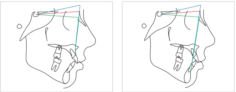
in-formation can be quantiied accurately by this function. However, this approach has an inherent deiciency in con-trast to 2-D analysis. The surface contour bound by the line cannot be described by the EFD. In order to address the above concern, we are developing a surface mapping function, illustrated in Figure 7. This function converts surface information into a series, which we make into a Figure 4 - A clockwise rotation of maxillomandibular complex creates more of a Class II relationship.
Figure 5 - A counter-clockwise rotation of maxillomandibular complex creates more of a Class III relationship.
Figure 6 - A true 2-D analysis using the Elliptical Fourier Descriptor.7
FILE 216H
CONSTANTS:
A1 = 33.889
B1 = 48.466 C1 = -31.317
D1 = -68.127 COEFFICIENTS:
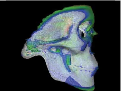
quantitative mathematical matrix. A total of 67 3-D skull images were converted to surface mapping functions, and the average of these functions was calculated and plotted in this illustration (Fig 7). Figure 8 is a colorized displacement map when the 67 skull average function and an individual skull function are superimposed. In this image we can visually understand the regional discrepan-cies between the average skull and an individual patient skull without the confusing numerical data that the linear measurement system provides. However, this function also has inherent deiciencies: the internal structures such as the sella and PT points are missing, and the boundary is not clean. By combining this function with EFD and conventional landmark points, the inal 3-D analysis will provide both surface and boundary information, and this will allow retroactive comparison with the previous data prior to the 3-D era. Figure 9 illustrates this combined function. My research team at UCLA already has made signiicant progress in this area, and we hope to have true 3-D analysis within a couple of years.
In the future, will it be practical to use such com-plex formulation in clinical orthodontics? In other words, the 2-D cephalometric analyses are simple to use even with its shortcomings. Will the 3-D analysis be user friendly?
I do not think that our current cephalometric analysis — which is more like 1-D or 1.5-D at best — is all that simple to use if you are looking for accu-racy. At UCLA we use a minimum of three different analyses for each case in order to fully understand the dento-skeletal relationship. Very often, these analyses disagree with each other: Which of the three analy-ses shown in Figure 10 is correct? Some orthodon-tic programs choose to only look at one analysis and avoid this confusion, but that does not mean they are operating with the correct information. Some may be able to identify the reason for this disagreement based on their experience and adjust their thinking accord-ingly, but this hardly is an objective means to deal with the problem.
Figure 8 - A colorized Displacement Map: This is a superimposition of a 67 skull average func-tion vs. an individual skull funcfunc-tion.
On the other hand the previous example of true 2-D analysis using the Elliptical Fourier Descriptor is much more accurate and visually descriptive (Fig 6). Eliminat-ing the numerical values and visualizEliminat-ing the plotted line make it much easier for the operator. This is also true with the true 3-D analysis method we are currently working on (Fig 8). Evaluation of the data is unequivocally simple. However, the potential problem in user friendliness may come from the data entry. Dealing with a 3-D structure requires labor intensive data entry process.
The answer to this problem will largely depend on the ability for the sotware program to identify the
mor-phological shape, process the DICOM data,10 and
auto-mate the steps involved. This part of development may take some time, but we will eventually get there.
Do you think that orthodontists will use a 3-D analysis in the near future, and will this alter our orthodontic diagnosis and treatment outcome?
I have no doubt that we will be using 3-D analysis in the future. The question of how soon mainly depends on the user-friendliness of the sotware. Also, the big-gest hurtle will be orthodontic politics. As with any-thing, there will be a battle between the traditionalists and the early adaptors.
Your second question is a much more interesting one. This really is the ultimate question when we have a new tool. Will this new and fancy system change how we see things and what we do? Old habits are hard to break, and here we are clearly dealing with human be-havior. Let’s say there is a man with an old car he has been driving for 20 years; it is an old car but a reliable one. One day this man decides to get a new toy; he buys himself a brand-new fancy car with all of the bells and whistles. It comes with all of the latest safety features, an automatic climate system, a hi-i sound system, a voice recognition system, a programmable seat position, and the latest GPS navigation system that illustrates traic low and potential detour routes. Would this car change the way this man goes to work and comes back home? Would it change his driving habits? Initially, he will continue to drive his new car the same way he drove his old car for the last 20 years. As he gets more famil-iar with the new features his new car provides, he will slowly change. Now, he listens to a satellite radio with no commercial interruptions, enjoys the auto climate system, and relies on the rear view camera when he backs up. As he gets used to his new navigation system, he has now discovered many shortcuts to his work, and he oten take detours recommended by the navigation Figure 10 - Three diferent analyses were applied for the same patient. The Steiner analysis (A) showed a Class II relationship, the Ricketts analysis (B) showed a Class I relationship, and the Sassouni analysis (C) showed a Class III relationship.
A B C
105.1 122.5
0.3
4.0
6.3
73.8
37.3
53.6 77.1 130.7 93.1
91.4
1.5 92.4
16.9
-1.9 143.9 32.9
85.7 82.7 3.0 102.0
139.5
0.7
16.2 143.9 0.8
2.2
73.8
ordered. Too oten, we order the standard set of x-rays regardless of the patient’s needs or the operator’s ability to evaluate the images. On the other hand, if one has an extraordinary knowledge in extracting valuable informa-tion from CBCT that could potentially help in achieving a better diagnostic and treatment outcome, I think that ordering CBCT routinely can meet the standard of care for this doctor. By not doing so, the patient’s care may be undermined. I was asked if the CBCT changes my treatment plan from the days when it was not available: It does not always change my treatment plan. However, this question should not be the criteria in deciding on the overall usefulness of CBCT. Dr. Angle was able to pro-vide orthodontic treatment without the help of cephalo-metric x-rays. During the initial diagnostic exam of the patients, most of us formulate how we would approach the treatments of these patients, and the x-ray indings merely conirm that our initial thinking was correct in the majority of the cases. This fact does not negate the necessity of the images we want to acquire. The use of CBCT is very much like this example. It gives us more precise and accurate information.
In short, my answer to your question is that it de-pends on the operator’s knowledge in utilizing CBCT. As there will be further developments in the utilization of this data, such as the 3-D analysis, 3-D growth pre-diction, and 3-D superimposition, the advantages in utilization of the 3-D image will exponentially prolifer-ate in the future.
We just discussed some of the cutting edge technology related to orthodontic diagnosis. Now let’s talk about the current orthodontic technique that may have changed our prac-tice: The micro-implants. How do you think the micro-implants have changed the orthodontic treatment planning?
Micro-Implant (MI) is slowly changing the face of orthodontics. Initially, they were used mainly as an-chorage devices yielding the uninspiring name TAD (temporary anchorage device). Many still believe that MI does not change the landscape of orthodontics, and that it is just another type of anchorage device. How-ever, there have been countless case reports pushing
the boundaries of conventional orthodontic belief.15,16,17
Now, we can distalize molars more than we have ever imagined, and we can intrude molars to correct skeletal system in order to avoid dreadful traic during
com-muting hours. Yes, his driving habits will change gradu-ally for a more eicient way. That is exactly how 3-D analysis will take over the orthodontic diagnosis and treatment planning: Slowly but surely.
What do you think about the ideal cone beam protocol for orthodontic patients? With the ra-diation concern, do you think we should request a 3-D scan for every orthodontic patient?
The recent article by the New York Times brought many concerns for both patients and practitioners re-garding increased radiation dosage associated with cone
beam images.11 This concern was also echoed by some
orthodontists. We are dealing with risk and beneit anal-ysis. If we look back at the history of radiographic usage in dentistry, we have come a long way. With the devel-opment of digital enhancement capability, we were able to cut the dosage to a fraction of what we were
accus-tomed to.12 When you consider the amount of radiation
our patients are subjected to when the CBCT is used, it is much lower than the full mouth x-ray series general dentists take annually or a conventional panoramic x-rays orthodontist ordered routinely a few decades ago before the digital radiograph became the norm. One may argue with a good justiication that if this amount of radiation were accepted to be safe in the past, then it must be safe
today.13 On the other hand, the thresholds for
accept-able radiation dosage have been reduced drastically in the recent years due to modern inventions.
Does this mean that we should not worry about the radiation associated with CBCT? Since it is well docu-mented that radiation exposure lasts over a lifetime, we should always try to minimize exposure whenever
pos-sible.14 This means that any radiation, including the
open bite cases. It does not stop there; we now can in-corporate MI for skeletal corrections. We can expand the maxillary arch without buccally tipping the denti-tion, allowing for more skeletal expansion. We can in-crease inter-canine width without compromising the la-bial plates. We can utilize MI in orthopedic corrections of patients with skeletal imbalance. We can safely treat patients with extremely high mandibular plane angles, and we can manage patients with deep bite and gingival smiles. The MI also has changed the biomechanics to a certain degree since our current biomechanics rarely
deal with an absolute anchorage.18
There is no doubt that MI has an enormous impact in orthodontic treatment planning by providing possi-bilities that have not been fully explored yet. It is not MI that has changed the orthodontics; it is rather how one can apply MI that has made the diference. In the last ive years, the World Implant Orthodontic Con-ference (WIOC) has been at the forefront of this efort to promote international collaboration of ideas. This meeting has been growing steadily, and it now attracts audiences from all over the world. Over 50 international speakers have participated in these meetings, and your very own Dr. Jorge Faber from Brasília (Brazil) was one of the renowned speakers. This sort of forum will con-tinue to advance MI utilization in orthodontics, and a brighter future is approaching more quickly.
How do we modify growth with micro-implants? Does it mean that some surgical cases can be treated without the surgery by this approach?
Growth modiication has been controversial in or-thodontics, with many conlicting clinical and research
indings.19,20 This conlict cannot be resolved easily
be-cause the skeletal changes in patients who have been treated with orthopedic devices — such as HG, FM, RPE, FA, etc. — are diicult to isolate because ortho-pedic force is applied to the dentition. Dentoalveolar changes are almost always present in these patients, and they mask and limit true skeletal changes. During the last ive years, I have tried to isolate the skeletal chang-es by eliminating the dentoalveolar changchang-es during the orthopedic correction, and the results were profoundly diferent than those of the previous studies. Not only we were able to eliminate these unwanted changes, but we were also able to reverse the existing dental
compensation, and maximize the skeletal correction.21
In many of the Class III cases, the dental de-compen-sation occur spontaneously as the skeletal relationship
improves, supporting the functional matrix theory.22
I have enclosed two clinical situations here supporting the above statements.
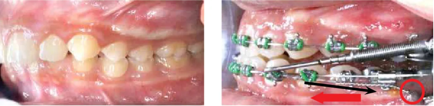
Figure 11 illustrates a Class II malocclusion being treated by ixed functional appliances and micro-im-plants in a thirteen-year-old boy. Mandibular denti-tions were retracted against the micro-implants placed in the posterior region as the mandible was pushed anteriorly by the ixed functional appliance (FA). This mechanic prevents the lower incisors from laring for-ward when the functional appliance is fully activated to achieve a Class I occlusion. Sometimes, two additional micro-implants can be placed in the maxillary alveolar bone if the distal movement of the maxillary dentition is a concern. The micro-implants allow true skeletal cor-rections without dental movements, and it also allows higher magnitude of orthopedic correction by eliminat-ing pre-existeliminat-ing dental compensations.
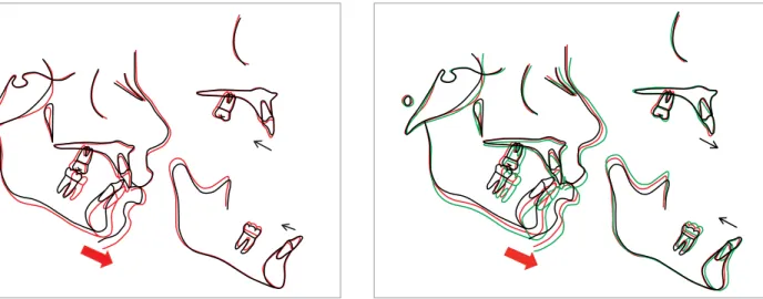
The cephalograms shown in Figure 12 illustrate that the mandible grew signiicantly more than the maxilla ater twelve months of FA treatment. When we compare the FA treatment outcome, it is important to make sure that the patient has the same condylar position (illustrated with thin red arrows in Fig 12). As the mandible grew in a forward direction, the airway also enlarged. Figure 13 shows the superimposition of the tracings generated from these radiographs. A sig-niicant diferential growth was noted between the two jaws. The lower incisors were decompensated with micro-implant supported retraction as the mandible grew forward assisted by the functional appliances. However, the maxillary dentition moved in a poste-rior direction because the micro-implants were used on the lower jaw only, and the posterior force generat-ed from the functional appliances drove the maxillary dentition posteriorly. As I have mentioned earlier, this movement can be ofset by utilizing micro-implants in the maxillary arch. In this particular case, the posterior movement of the maxillary dentition was desired due to patient’s protrusive upper lip.
appliance therapy, and the green tracing was gener-ated ten months thereater. Surprisingly, the mandible continued to outgrow the maxilla and the lower inci-sor position became more upright as the jaw relation-ship changed. Moreover, the maxillary incisor started to procline as well, cancelling the previous posterior move-ment during the FA treatmove-ment. This phenomenon is in
full support of Moss’s Functional Matrix Theory.22
All the years of controversy related to FA therapy can be put to a rest if we can isolate the orthopedic changes without the dental side efects. Ater treating many pa-tients with Class II malocclusion, I am optimistic that we can create true orthopedic changes. Obviously, the long-term follow up is necessary to legitimize this claim, and results will be coming.
A similar concept can be applied to the Class III malocclusions as well. Figure 15 illustrates the modi-fied Hyrax for orthopedic correction. The body of
the Hyrax is fitted closely to the palatal vault, and four MI were used to fixate it to the palate on either side of the midpalatal suture. As the Hyrax is acti-vated, the expansion force is localized near the mid-palatal suture and causes a maxillary expansion, and this force may disarticulate the circummaxillary
su-tures.23 This apparatus also has two face mask (FM)
hooks attached to the molar bands, and the protrac-tion force generated by the face mask will be directed mainly at the maxilla. Because the apparatus is firmly attached to the palatal bone, the vertical dental move-ments are controlled. This means that even a high-angle Class III patient can be treated without the fear of creating an anterior open bite. The high-angle Class III patients are considered to be the most chal-lenging problem in orthodontics by many, and I will present a high-angle Class III patient who was treated using the above treatment protocol.
Figure 11 - A Class II malocclusion treated with the ixed functional appliance and micro-implants: A forward movement of mandible by the ixed functional appliances (red arrow) and retraction of the mandibular dentition using the micro-implants (black arrow).
▶
Figure 12 - Before the functional appliance therapy (A), after twelve months of functional appliance therapy (B).
▶
Figure 13 - Superimposition of the tracing generated from the radiographs taken before (black) and after (red) the functional appliance therapy for twelve months.
Figure 15 - The Hyrax with MI and FM hooks.
Figure 14 - Superimposition: before the FA treatment (black), after twelve months of FA treatment (red), and ten months after terminating the FA treat-ment (green).
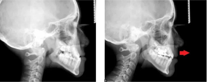
This patient presented with a MP-FH angle of 31.4 degrees (norm: 24.5) and a Wits measurement of -20.8 (norm:-1.0). She was an eleven-year-old female patient presented with a high-angle Class III skeletal relation-ship with anterior and posterior crossbite. Ater a four-teen-month FM treatment, both the skeletal and dental relationships have improved (Figs 16 and 17).
The superimpositions shown in Figure 18 illustrate that the maxilla grew forward signiicantly more than the mandible during the fourteen months of FM treat-ment. More interestingly, the maxillary and mandibu-lar incisors retroclined and proclined respectively as the skeletal relationship improved. Despite the fact that none of these teeth had any orthodontic appliance, they spontaneously decompensated as the jaws were aligned. Although her face grew in forward and downward di-rection, the mandibular plane angle did not change. Table 1 conirms the above statements.
Again, we must ask if these results are stable. Figure 19 shows a seven-month follow up ater terminating the FM treatment. It seems that maxillary growth from the FM treatment held stable, but the mandible grew a bit more than the maxilla. This reairms the previous study that skeletal Class III patients are predisposed to
grow in a Class III manner.23 Some authors suggested
an overcorrection in order to compensate for the
fu-ture growth.23 It is important to closely follow these
patients until their growth rests.
Do you think we can use the same strategies for adult patients?
In non-growing patients, this approach would not work. However, there have been reports of success in ex-pansion of maxillary width, much like in Surgically
As-sisted Rapid Palatal Expansion (SARPE).24 At UCLA, we
expanding and constricting the maxillary suture
repeti-tively using the MI supported expander.24 This process
simulates the distraction osteogenesis and the maxilla can be rapidly protracted. This may lead us to a breakthrough, but currently the sutural growth in adult patients sounds too good to be true. As far as Class II adult patients with retrognathic mandibles are concerned, I have not heard of any ground-breaking ideas yet.
Based in your vast experience with micro-im-plants, can you briefly discuss the important fac-tors related to the stability of MI?
The stability of MI can be divided into the primary and secondary stabilities. The primary stability comes from the mechanical interlocking between the MI and the surrounding bone.
The factors involved in the primary stability can be further divided into biological and mechanical factors. Bone density, bone volume, tissue thickness, type of gingival tissue, vital structures and others, constitute the biological factor. The mechanical factors largely depend on MI design, and they include diameter, length, shape,
thread density, thread pitch, thread count, etc.25 It should
be also noted that the cortical bone is responsible for the MI stability and cancellous bone plays a minor role. The biological factors are inherent to our patients, and it is not easy to change them. We should try to ind the MI placement site carefully in order to maximize stability. However, the most stable position may not be the most advantageous for orthodontic biomechanics, and one may choose to settle for a less stable site. Since MI sta-bility is the most frustrating problem we face, I suggest Figure 16 - Before the FM treatment (A), after 14 months of FM treatment (B).
▶
Figure 17 - The MI supported FM treatment for 14 months.
Table 1 - Comparison of cephalometric measurements.
Measurement Initial Phase I (20 months with facemask)
SNA (degrees) 81,4 85.1
SNB (degrees) 83,0 82.4
ANB (degrees) -1,6 2.8
Wits (mm) -28,0 -6.3
U1.SN (degrees) 106 103
L1.GoGn (degrees) 74 83
FMA (degrees) 31 30
SN.GoGn degrees) 35 36
Figure 18 - Superimposition generated from tracing before the FM treat-ment (black) and after (red)
Figure 19 - The superimposition generated from the tracings before the FM treatment (black), after the FM treatment (red), and seven months after the termination of FM treatment (green).
inding the most stable site for MI and working out the orthodontic mechanics instead of settling for a less sta-ble site. Being creative with orthodontic biomechanics is critically important. The mechanical factor is where we have much more control because we can manage these variables. There are numerous MI designs avail-able in the marketplace, and understanding the factors
associated with each design will help in choosing the
right MI for a particular circumstance.25
becomes irrelevant. The osseointegration may play a much more signiicant role in the stability ater bone remodeling takes place in the surrounding area. Sec-ondary stability also can be divided into biological and mechanical factors. Bone metabolism, bone density, etc. inluence the biological factors, and MI design con-tributes to the mechanical factor. As with the primary stability, the mechanical factors are easier to control. More surface area of MI is in contact with the bone, more osseointegration can be established, and the sur-face texture and sursur-face treatment can facilitate
osseoin-tegration as well.26
In recent years, some clinicians have tended to-ward overuse of micro-implants in clinical orth-odontic treatment. Yet, literature still lacks some information about the long-term response of surroundings tissues (i.e. roots) and the stability of some clinical results. Do you think, based in the current literature, we should treat with cau-tion or dive in head first?
Any new procedure should be used with caution. The safety of MI has been well established, but there have been reports of surrounding tissue damages as well. The decision to use MI should follow ater the risk and beneit analysis as with the CBCT. If MI can be placed safely without tissue damages, there is no reason to avoid its usage. If MI has to be placed in the area with a risk, every precaution should be considered. Gener-ally speaking, the majority of the problems are related to root injury, and this problem can be largely eliminated by choosing the site carefully and selecting the proper MI design. The recent trend is utilizing the palatal area and using the MI with small diameters in attempts to
reduce the root contact.27
I heard that you have developed a new micro-implant design. Can you briefly describe this new project?
The objective of this novel design was to avoid the vital structures, to maximize the bone contact area within the cortical bone, to reduce the insertion torque (for easy placement), to maximize the remov-al torque (for stability), and to maximize the
osseo-integration (for the secondary stability).28 This MI is
only 2.0 mm in length, to avoid contacting the root and neurovascular bundles, but 3.0 mm in diameter to maximize stability (Fig 20). It is hollow inside in order to reduce insertion torque and to increase bone contact. The total surface area in contact with corti-cal bone is larger than in conventional MI. The inter-nal chamber is reverse-tapered to facilitate insertion. The bone trapped inside the chamber will undergo re-modeling process and ill the void. This creates a me-chanical trap within the cortical bone and more osseo-integration with MI internally, aiding in the secondary stability. Our studies, part 1 and part 2, were published
in The Angle Orthodontist journal,28 and they
illus-trate, in vitro, the stability of this Novel MI. Our most recent in vitro study also demonstrated its superior sta-bility in various clinical simulations. We are now ready for a clinical trial of this design at UCLA.
The orthodontic community got excited with the idea of decreasing treatment time by using the self-ligated brackets, but after evaluating recent papers, it was found that one cannot treat pa-tients any faster. What are your thoughts on this?
It is well established that the self-ligating brackets
do not signiicantly reduce treatment time.29 I am
All around us, there are advertisements promoting ap-pliances, such as Invisalign, Damon brackets, and In-cognitos. I understand that the manufacturers of these products are trying to convince the public because they have to sell these products. Many of us caved into public pressure and provide the services that the public demands, which oten may not be the best treatment choice. It is also sad to see many orthodontists mindless-ly promoting the talking points of these manufacturers, claiming that these products are superior and/or more eicient without concrete scientiic evidence.
I strongly believe that we all should go back to skill-based orthodontics and treat these new systems as mere tools to achieve our goals. I use MI extensively and sometimes achieve treatment goals that would not have been possible in the past, but it is not the MI that treated patients. It is what I do with this novel tool that matters. If you are looking for a good meal, you will look for a restaurant with a great chef, and you would not care much what kind of knife this chef uses. It is what the chef does that matter, not which tools the chef uses.
If we truly want to reduce treatment time, we have to consider both factors, biomechanics and bone biol-ogy. The orthodontists have a tendency to focus more on biomechanics than bone biology. Over the years, a large volume of work has been produced on biome-chanics of orthodontics, and they have advanced sci-ence. Perhaps that is why we sell our souls to these new devices that claim to make orthodontics easier and more eicient. New hi-tech arch wires, new appli-ances, and new materials have improved our treatment protocols, but I realize that the improvement in treat-ment speed has been marginal at best. No matter what new devices we may have, we cannot move teeth any faster than the rate of bone remodeling.
Here are my thoughts on reducing treatment time. It would be far more eicient if we can afect the bone remodeling process. The Wilco brothers introduced accelerated tooth movement, and the results were
un-matched by any biomechanical invention to this date.30
The key is “how do we achieve Wilco-like results with-out such an invasive procedure?” Accelerated tooth movement (ATM) is one of my research projects at UCLA, and we hope to have good news soon.
An interesting analogy could be associated to mi-cro-implant cases: Do you think we can decrease treatment time by using micro-implants?
1. Baumrind S. Adult orthodontic therapy: extraction versus non-extraction. Clin Orthod Res. 1998;1(2):130-41.
2. Baccetti T, Franchi L, Stahl F. Comparison of 2 comprehensive Class II treatment protocols including the bonded Herbst and headgear appliances: a double-blind study of consecutively treated patients at puberty. Am J Orthod Dentofacial Orthop. 2009;135(6):698.e1-10; discussion 698-9.
3. Stockstill J, Greene CS, Kandasamy S, Campbell D, Rinchuse D. Survey of orthodontic residency programs: teaching about occlusion, temporomandibular joints, and temporomandibular disorders in postgraduate curricula. Am J Orthod Dentofacial Orthop. 2011;139(1):17-23.
4. Monaco A, Cattaneo R, Spadaro A, Marzo G. Neuromuscular diagnosis in orthodontics: efects of TENS on the sagittal maxillo-mandibular relationship. Eur J Paediatr Dent. 2008;9(4):163-9.
5. Broadbent BH. A new x-ray technique and its application to orthodontia. Angle Orthod. 1981;51(2):93-114.
6. Madsen DP, Sampson WJ, Townsend GC. Craniofacial reference plane variation and natural head position. Eur J Orthod. 2008;30(5):532-40. Epub 2008 Jul 16. 7. Moon W. A numerical and visual approach for measuring the efects of
functional appliance therapy: Fourier Descriptors. In: Lestrel PE. Fourier Descriptors and Their Applications in Biology. 1st ed. Cambridge: Cambridge University Press; 1997. p. 340-58.
8. Lestrel PE, Ohtsuki F, Wolfe CA. Cranial vault shape in fossil hominids: Fourier descriptors in norma lateralis. Homo. 2010;61(5):287-313.
9. Farronato G, Garagiola U, Dominici A, Periti G, de Nardi S, Carletti V, Farronato D. “Ten-point” 3D cephalometric analysis using low-dosage cone beam computed tomography. Prog Orthod. 2010;11(1):2-12.
10. Rueda S, Alcañiz M. An approach for the automatic cephalometric landmark detection using mathematical morphology and active appearance models. Med Image Comput Comput Assist Interv. 2006;9(Pt 1):159-66.
11. Bogdanich W, McGinty JC. Radiation worries for children in dentists’ chairs. The New York Times [Internet]. 2010 Nov 22. [access in 2010 Nov 22]. Available from: http://www.bu.ufsc.br/ccsm/vancouver.html.
12. Yoo JY, Chung MJ, Choi B, Jung HN, Koo JH, Bae YA, Jeon K, Byun HS, Lee KS. Digital tomosynthesis for PNS evaluation: Comparisons of patient exposure and image quality with plain radiography. Korean J Radiol. 2012;13(2):136-43. 13. Jacobs R. Dental cone beam CT and its justiied use in oral health care. JBR-BTR.
2011;94(5):254-65. Review.
14. Jungowska-Klin B. Cumulative efect of X-ray radiation and inlammatory reaction on the circadian rhythm of tyrosine aminotransferase in the liver of mice. Acta Physiol Pol. 1980;31(2):131-9.
15. Dholakia KD, Bhat SR. Double impact: intrusion of two mandibular molars using an SAS: a case report. Orthodontics (Chic.). 2011;12(4):378-85.
16. Coscia G, Addabbo F, Peluso V, D’Ambrosio E. Use of intermaxillary forces in early treatment of maxillary deicient Class III patients: results of a case series. J Craniomaxillofac Surg. 2012;40(8):e350-4.
17. Upadhyay M, Yadav S, Nanda R. Vertical-dimension control during en-masse retraction with mini-implant anchorage. Am J Orthod Dentofacial Orthop. 2010;138(1):96-108.
18. Favero L, Giagnorio C, Cocilovo F. Comparative analysis of anchorage systems for microimplant orthodontics. Prog Orthod. 2010;11(2):105-17. Epub 2010 Oct 8. 19. King G. Early orthodontic growth modiication treatment for Class II patients may
provide better skeletal and dental outcomes after subsequent comprehensive permanent dentition orthodontic treatment with less need for complex interventions and greater eiciency. J Evid Based Dent Pract. 2011;11(1):49-51. 20. Johnston LE. If wishes were horses: functional appliances and growth
modiication. Prog Orthod. 2005;6(1):36-47.
21. Moon W, Khullar R. Orthodontic treatment of Class III malocclusion (Textbook). In: Class III orthopedic treatment using skeletal anchorage. [s.n.]: Bentham eBook. In Press.
22. Moss ML. The functional matrix hypothesis revisited. 4. The epigenetic antithesis and the resolving synthesis. Am J Orthod Dentofacial Orthop. 1997;112(4):410-7. Review.
23. Turley PK. Managing the developing Class III malocclusion with palatal expansion and facemask therapy. Am J Orthod Dentofacial Orthop. 2002;122(4):349-52. 24. Wang YC, Chang PM, Liou EJ. Opening of circumaxillary sutures by alternate
rapid maxillary expansions and constrictions. Angle Orthod. 2009;79(2):230-4.
REFERENCE S
25. Holm L, Cunningham SJ, Petrie A, Cousley RR. An in vitro study of factors afecting the primary stability of orthodontic mini-implants. Angle Orthod. 2012;82(6):1022-8.
26. Ikeda H, Rossouw PE, Campbell PM, Kontogiorgos E, Buschang PH. Three-dimensional analysis of peri-bone-implant contact of rough-surface miniscrew implants. Am J Orthod Dentofacial Orthop. 2011;139(2):e153-63.
27. Wilmes B, Drescher D, Nienkemper M. A miniplate system for improved stability of skeletal anchorage. J Clin Orthod. 2009;43(8):494-501.
28. Hong C, Truong P, Song HN, Wu BM, Moon W. Mechanical stability assessment of novel orthodontic mini-implant designs: Part 2. Angle Orthod. 2011;81(6):1001-9.
29. Celar AG, Schedlberger M, Dörler P, Bertl MH. Systematic review on self-ligating vs. conventional brackets: initial pain, number of visits, treatment time. J Orofac Orthop. 2013;74(1):40-51.
30. Wilcko MT, Wilcko WM, Pulver JJ, Bissada NF, Bouquot JE. Accelerated osteogenic orthodontics technique: a 1-stage surgically facilitated rapid orthodontic technique with alveolar augmentation. J Oral Maxillofac Surg. 2009;67(10):2149-59.
André Wilson Machado
» Associate Professor of Orthodontics, UFBA (Brazil). Assistant Professor of the Master in Orthodontics program at UCLA. PhD in Orthodontics, UNESP-Araraquara / UCLA. MSc in Orthodontics, PUC-Minas (Brazil).
Barry Briss
» Professor and Chairman of Post-Doctoral Orthodontics, Tufts University. Certificate in Orthodontics from Tufts University School of Dental Medicine. American Board of Orthodontics certified orthodontist.
Greg J. Huang
» Professor and Chairman, Department of Orthodontics, University of Washington. MPH in Epidemiology and MSD in Orthodontics, University of Washington.
Richard Kulbersh
» Professor and Chairman, Orthodontic Graduate Program, University of Detroit Mercy . MSc in Orthodontics, University of Detroit Mercy Dental School. American Board of Orthodontics certified orthodontist.
Sergei Godeiro Fernandes Rabelo Caldas