The evolution of cephalometric diagnosis in
Orthodontics
Maurício Barbosa Guerra da Silva1, Eduardo Franzotti Sant’Anna2
Introduction: Although the development of CT have represented a landmark in diagnostic imaging, its use in Den-tistry turned out very discretely over the years. With the appearance of programs for analysis of three-dimensional images, speciic for Orthodontics and Orthognathic surgery, a new reality is being built.
Objective: The authors of this study aim to inform the orthodontic society of fundamentals about digital cephalomet-ric radiographic image and computed tomography, discussing about: Field of view (FOV), radiation doses, demands for the use in Orthodontics and radiographic simulations.
Keywords: Cone-Beam Computed Tomography. Digital dental radiography. Computer-assisted diagnosis.
How to cite this article: Silva MBG, Sant’Anna EF. The evolution of cephalomet-ric diagnosis in Orthodontics. Dental Press J Orthod. 2013 May-June;18(3):63-71.
Submitted: September 15, 2009 - Revised and accepted: December 29, 2010
» The authors report no commercial, proprietary or financial interest in the products or companies described in this article.
Contact address: Eduardo Franzotti Sant’Anna
Av. Professor Rodolpho Paulo Rocco – Cidade Universitária - Ilha do Fundão CEP: 21.941-590 – Rio de Janeiro/RJ – Brazil
E-mail: [email protected] 1 Student of post-graduate education in Orthodontics at UFRJ.
2 Assistant professor of Orthodontics at UFRJ.
» The patient displayed in this article previously approved the use of her facial and intraoral photographs.
Introdução: apesar do desenvolvimento da tomograia computadorizada ter representado um marco na área do diag-nóstico por imagem, sua utilização em Odontologia deu-se de forma muito discreta ao longo dos anos. Com o sur-gimento de programas para análises de imagens tridimensionais, especíicos para Ortodontia e Cirurgia Ortognática, uma nova realidade está sendo construída.
Objetivo: os autores do presente artigo têm o objetivo de informar à sociedade ortodôntica fundamentos sobre ima-gem radiográica cefalométrica digital e tomograia computadorizada, discutindo sobre o campo de visão (FOV), doses de radiação, exigências para o uso em Ortodontia e simulações radiográicas.
INTRODUCTION
In 1931, Orthodontics consecrated the era of ceph-alometry, from the historical works that presented to the orthodontic community, the cephalostat, device that allows the placement of the patient’s head always
on the same position.5,13 With this device, it was
pos-sible obtaining the serial radiographs that provided
more accurate studies on the human facial growth.6
This year is considered a landmark for Orthodontics because of the evolution of the specialty as science.
In the late 60s, it began the era of computed
cepha-lometric radiography.24 The technological evolution in
data processing enabled the development of diferent programs that calculate distances and angles of the ceph-alometric tracing; reducing the manual work required on studies and consequently accelerating the researches where the cephalometric evaluation is necessary.
With computed tomography, using specific soft-wares, it began to be considered the possibility of simulating radiographs used in orthodontic diagnosis such as panoramic, lateral and frontal cephalometric; with the advantage of taking only one exam.
The role of extracting two-dimensional images from three-dimensional images becomes extremely important in this transition or change of paradigm from the 2D to the 3D diagnosis, so that the clinician can continue to use the same cephalometric analysis, until it is established consecrated three-dimensional analysis in orthodontic literature and become appeal-ing to the day-by day practice. At irst sight, it seems paradoxical the reconstruction of a 3D model and sub-sequent return to a 2D image, but this can make easier the progressive introduction of CBCT to the practice
of the orthodontist21 and research.
Because of the progressive technological evolution for obtaining auxiliary images on the orthodontic diagnosis, the authors objective is to instruct the orthodontist about the use of the latest techniques for obtaining images.
LITERATURE REVIEW
Digital cephalometric radiography
The digital radiography is a versatile and reliable technology that increases the quality of diagnosis and the possibilities of image sharing in Dentistry.
Digital radiographic images can be produced by different means. Scanners with a transparency adapt-er, scanners of slides or any digital camera can be used
to convert an existent analog radiograph to a digital image. This approach does not need high investment and allows bringing any radiograph to the digital sys-tem. The images produced by this technique usually are called indirect digital radiographs.
There are two systems, more advanced, for produc-tion of digital images, without a precursor radiograph: The direct and the semidirect. The direct digital im-ages are obtained using a CCD sensor (charge-coupled device) and the semidirects using a system with a
phos-phor plate, as alternative to radiographic ilm.29
On the direct system, the images are obtained and automatically exported to a computer attached to the X-ray device. On the semidirect, the capture source is a plate that contains crystals of phosphorus photo-stimu-lated by X-ray and that needs one more step to obtain-ing the images, which is the readout of the phosphor plate, performed by a scanner speciic for this function, that sends the image to an attached computer.
It can be enumerated the advantages that the system of digital radiography ofers over the conventional:
1) Allows visualization of the image while patient is still on the chair.
2) Reduces the risk of inappropriate association of the film to another patient’s file.
3) Eliminates the possibility of printing mistakes. 4) Allows immediate correction of irregularities
on brightness and contrast.
5) Promptly performs calibration of images. 6) Facilitates the overlap of the digital radiograph
with the digital image.8,25,30
7) Provides images with quality superior than the
conventional.23
Computed tomography
The computed tomography is a method of diagnos-tic imaging that uses x-radiation and allows obtaining the reproduction of a section of the human body in any of the three planes of space. It allows the visualization of the structures in slices, especially mineralized tis-sues, with good deinition, allowing the diagnosis of
possible alterations, in three dimensions.9,12
during examination, moves towards inside the gantry and 3) the computer, which reconstructs the tomo-graphic image from the information obtained on the gantry (Fig 1). The CT technician or operator follows the examination through the computer, usually lo-cated outside the room that accommodates the gantry and the table, separated by a lead glass wall.
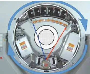
During exam, inside the gantry, the X-rays tube spin inside the stationary ring of receptors (Fig 2). The signals received by the detectors depend on the absorption of the tissues crossed by the radiographic beam and are recorded
and processed, mathematically, on the computer.9
On the first generation of medical tomographs, the system captured only one slice at each spin of the set inside the gantry. The latest tomographs can obtain up to 64 slices simultaneously, reducing substantially the scanning time, besides improving the quality of
the image and reducing substantially the doses of
ra-diation, when compared to their predecessors.15,26
When the patient has metallic restorations or uses metallic orthodontic appliance during examination, certain amount of artefacts affects the quality of the obtained image (Fig 3) and that was a remarkable dis-advantage for that the fan-beam tomograph was not
diffused in the dental area.14,28
Aiming to solve the limitations of conventional computed tomography, the department of radiology of the school of Odontology from the University of Nihon (Japan) developed, in 1997, a tomograph spe-cific for Dentistry, using new technology, known as
Cone-Beam Computed Tomography.2
Contrary to traditional tomographs, which are big and present high cost of acquisition and maintenance, the Cone-Beam tomograph has reduced size and can be installed in small physical spaces besides scanning only the patient’s head, meeting the Dentistry needs. This technology allows the reproduction of three-dimensional images of mineralized tissues with mini-mum distortion, lower cost and lower dose of radiation
compared to traditional computed tomography.22,26
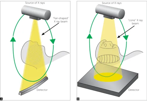
The conventional tomographs used a narrow source of beam, fan beam, that irradiated an arch-shaped re-ceptor, obtaining one slice at a time. This required the reconstruction of the object slice by slice for obtaining its three-dimensional representation (Fig 4A). On the CBCT, the rays are conically directed on a large lat sensor while both rotate around the patient’s head, so that in a single rotation of the set (Fig 4B), which lasts between 20 and 40 seconds, nearly 360 2D slices are performed on the three planes of space. Then, a sot-ware reorganizes the slices in a 3D model including all irradiated structures, which can be digitally visual-ized in diferent ways. Compared to the conventional CT, the CBCT uses signiicantly lower radiation, for it performs a single spin around the patient.
The representation of a two-dimensional image is composed of pixels, the short for “picture element”. It’s the smallest part of a digital image and each one of these parts contains information that determines its charac-teristics. The pixel is used as unit of measurement to describe the geometric dimension of an image and the larger the amount of pixels per inch, better the quality or resolution of the image. Each pixel brings the
informa-tion about the level of gray or color that it represents.20
Figure 2 - Inner part of the gantry showing the source of X-rays, the recep-tor and the direction of spin of the components. (Source: Buzug33, 2008).
Figure 1 - Traditional computed tomograph: A) gantry and table; B) tomo-graph operator and computer.
Figure 3 - Artefacts caused by metallic restorations on the images. On image A, axial incision without artefact, from B to D, dif erent levels of artefacts are found depending on the amount of metal present on the section; E and F show reconstructions of coronal and sagittal slices respectively; i gures G and H
show the 3D visualization emphasizing the axial slices that contained metals. Source: Buzug,33 2008.
Figure 4 - Draft of projection of X-rays showing the dif erences on the obtention of image be-tween a simple detector (A) and the cone beam (B). Source: Sukovic,27 2003.
Source of X rays Source of X rays
“cone“ X ray beam “Fan-shaped”
X ray beam
Detector Detector
A
A
C
F
H E
G
B
B
Field of view
The ield of view or FOV of the cone beam de-vices, normally work with windows between 6-in and 12-in. The FOV of 6-in is used when you want im-ages restrict to only one of the jaws. On the FOV of 9-in it is possible to visualize both jaws, and depending on the size of the patient, all the craniofacial complex. However, when you want all the craniofacial region inserted in the study, as in cases where you want to cephalometrically analyze the patient, you must select
the FOV of 12-in (Fig 7).3,7,16,18
The structures and reference points used on the orthodontic analysis comprise the skull base, the facial bones and the dentition, which requires a ield of view larger than the used on the analysis for implants. In general, the orthodontist needs to visualize the nasion, on the anterior-superior border of the image, and the mandibular points pogonion, gnathion and mentum on the anterior-inferior border. The posterior ield of view must include the sella turcica, the TMJs (condyle point), skull base (basion), and the posterior contour of the mandible (gonion). Besides, the vertebrae un-til C4, should be visible on the tomography, allowing
analysis of the skeletal maturation.21
The volumetric data are formed by voxels, which are the smallest structures makers of the 3D image. It would be a pixel with one more dimension, the depth. Its size determines the resolution of the three-dimen-sional image (Fig 5). On the CT, the voxels are aniso-tropic, rectangular cubes where the largest dimen-sion is on the axial plan. Its depth is determined by the thickness of the tomographic section. Contrary to CTs, all CBCT devices generate images with isotropic
voxels, i.e., similar in all three dimensions.3,26
On Fig-ure 6 it can be visualized a plan emphasizing the difer-ence between pixels and voxels.
Figure 5 - Images of the same region (vertebra) with diferent coniguration of CT. Images on the left were performed with slices thickness of 6 mm, while on the right with 0,5 mm. Source: Buzug,33 2008.
Figure 6 - Scheme showing the pixels in two dimensions (x,y) and the voxels in three dimensions (x,y,z).
Figure 7 - Image showing the diferent sizes of FOV (6, 9 and 12 inches).
3D Axial 3D
Radiation doses
One of the main disadvantages of CT is the fact that it uses x-radiation, which has negative efect on the human body, especially for the capacity to cause mutation, detectable in cells that multiply quickly, as in the case of cells from the buccal mucosa. Although the risk of developing anomalies is low, it is not recom-mended the performance of CTs on pregnant women,
considering very carefully the risks and beneits.1,17,19
It is known in radiological literature that a full periapical exam may vary from 33 to 150 micro-sieverts (µSv), depending on the film and type of
col-limation used.4,32 A panoramic review varies from
2,5 to 6,2 µSv (digital) and from 3 to 10 µSv (film), depending on the equipment and the quality of the
required image.10 Effective doses for digital
cephalo-metric radiographs vary from 1,1 to 3,4 µSv,
depend-ing on the type of system,11 while the reported dosage
with the use of film is of 2,3 µSv.31 As parameter, it is
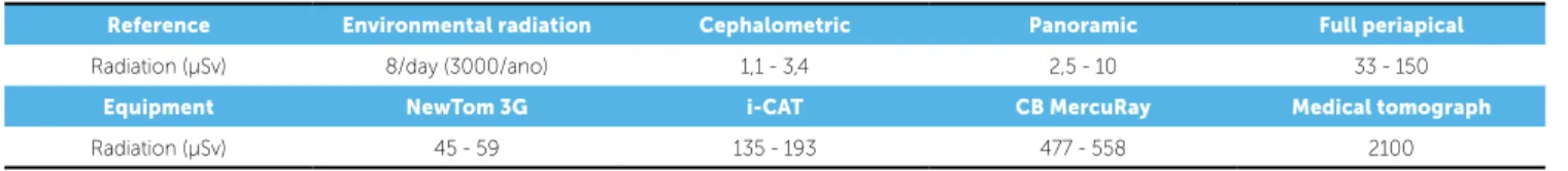
known that the mean environmental radiation (cos-mic radiation, radiation from the ground, UV rays) is of 3000 µSv/year (around 8 µSv/day), which means that the dosage of a cephalometric and panoramic ra-diograph is equivalent to half of a day and to one day
of environmental radiation, respectively (Table 1).21
A research compared the dosimetry of three to-mographs, all using the ield of view of 12-in, exactly
the one of orthodontic interest.18 Various doses were
found, measurements in µSv according to norms by the International Committee of Radiologic Protec-tion (ICRP) of 1990 and 2005, so that the i-CAT presented dosage from 135 to 193 µSv, higher than the NewTom (45 to 59 µSv), while the CB Mer-cuRay showed a dosage signiicantly higher, from 477 to 558 µSv. That is, the i-CAT and the MercuRay presented doses 3 to 3,3 times and 9,5 to 10,7 times higher than the NewTom, respectively. Besides, the CBCT equipments presented doses from 4 to 42 times higher than a panoramic radiograph (6,3-13,3 µSv).
The authors concluded that the dosage ranged sub-stantially depending on the equipment, on the FOV and on speciic technical factors (mA and kV). On the i-CAT, the variation of FOV from 12-in to 9-in re-duced the dosage from 135-193 µSv to 69-105 µSv. The CB MercuRay, for example, tested on FOV of 12-in with 10 mA/100 kV and 15 mA/120 kV, showed values of 477-558 µSv and 847-1025 µSv, respectively.
Orthodontic demands
Some basic requirements must be considered so that a CBCT equipment is appropriated for orthodontic di-agnosis, such as: Have a ield of view including all struc-tures of orthodontic interest and allow visibility of sot and hard tissues, with good resolution. It is known that this method is ideal to irradiate teeth and bones, while other methods, as magnetic resonance, would be more recommended for better resolution of sot tissues.
The advantage of relative short period of exami-nation, when compared to fan beam tomograph, may affect the quality of the final image, because it reduces the possibility of artefacts by movimen-tation of the head. Some equipments bring a head positioner, with support for the mentum and splint for the forehead, but its use must be avoided believ-ing that it may cause distortion on the soft tissues,
besides affecting the mandibular positioning.21
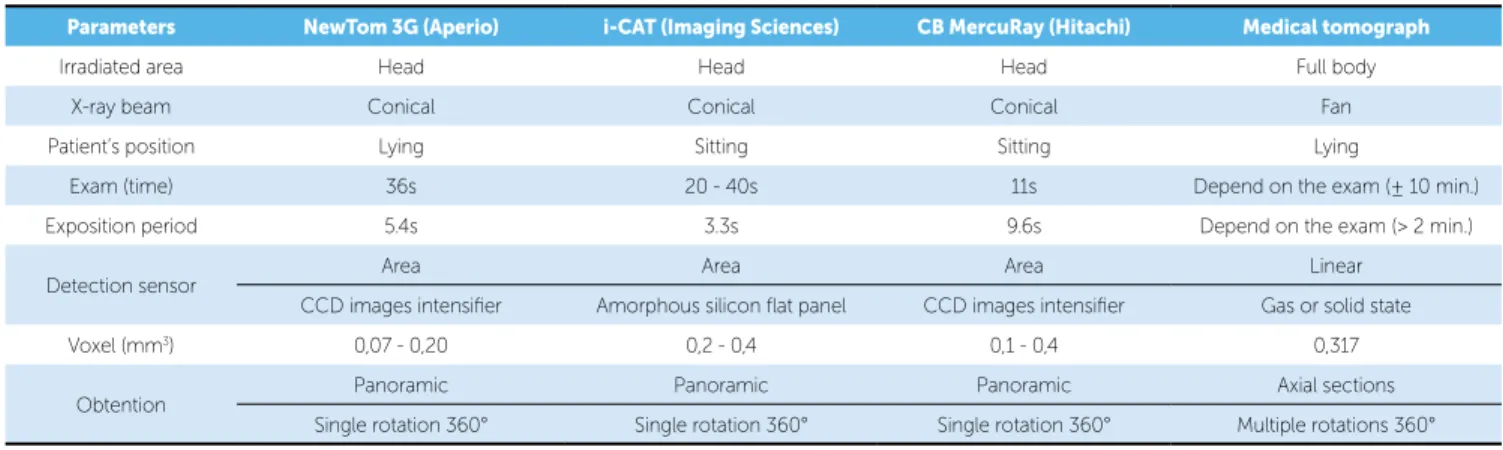
The cone beam computed tomographs most known on the international market with adequate characteristics for orthodontic use are the NewTom 3G (AFP Imaging, Elmsford, New York, USA), i-CAT (Imaging Sciences International, Hatfield, Pennsylvania, USA) and CB MercuRay (Hitachi Medical Corporation, Tokyo, Japan) (Table 2).
Besides the equipments available today, the trend is that manufacturers develop new systems present-ing better x-ray sensors and programs of reconstruc-tion and visualizareconstruc-tion of the images improved and of easy handling.
Reference Environmental radiation Cephalometric Panoramic Full periapical
Radiation (µSv) 8/day (3000/ano) 1,1 - 3,4 2,5 - 10 33 - 150
Equipment NewTom 3G i-CAT CB MercuRay Medical tomograph
Radiation (µSv) 45 - 59 135 - 193 477 - 558 2100
Radiographic simulation
Through CBCT technology, all the radiographs possible on the dentomaxillofacial region are obtained in a single exposition, for the technique enables the
capture of all the object’s volume, in a period infe-rior to 1 minute. Through this, the orthodontist has diagnostic quality on periapical, panoramic, cephalo-metric, occlusal, spatial view of temporomandibular
Table 2 - Comparison between characteristics of a medical tomograph and a cone beam one. Source: Adapted from Danforth,7 2003.
Parameters NewTom 3G (Aperio) i-CAT (Imaging Sciences) CB MercuRay (Hitachi) Medical tomograph
Irradiated area Head Head Head Full body
X-ray beam Conical Conical Conical Fan
Patient’s position Lying Sitting Sitting Lying
Exam (time) 36s 20 - 40s 11s Depend on the exam (± 10 min.)
Exposition period 5.4s 3.3s 9.6s Depend on the exam (> 2 min.)
Detection sensor Area Area Area Linear
CCD images intensiier Amorphous silicon lat panel CCD images intensiier Gas or solid state
Voxel (mm3) 0,07 - 0,20 0,2 - 0,4 0,1 - 0,4 0,317
Obtention Panoramic Panoramic Panoramic Axial sections
Single rotation 360° Single rotation 360° Single rotation 360° Multiple rotations 360°
Figure 10 - Prospective cephalometric radiograph including only the right side of the image.
Figure 11 - Prospective cephalometric radiograph including only the left side of the image.
Figure 8 - Illustration of the coniguration with divergence or parallelism of X-rays. Note the detail on the left.
joint (TMJ), as well as has the possibility to separate the right and left side of the face, on cephalometric
analysis, reducing the overlap of bone structures.27
The cephalometric radiograph can be simulated from a tomograph with diferent characteristics, pre-senting advantageous possibilities. On the simulation of cephalometric radiograph, the volumetric model re-built from the tomographic sections is spatially orient-ed by the operator, as if positionorient-ed the patient’s head on the cephalostat of conventional teleradiographic equipment, and then it is projected on a two-dimen-sional image (Fig 9). On the moment of the radio-graphic simulation, some sotware as the Dolphin Im-aging 3D (Dolphin ImIm-aging & Management Solutions, Chatsworth, California), and the InVivo (Anatomage, San Jose, California, USA) allow adjustments related to divergence or parallelism of rays (Fig 8). It is pos-sible to choose between two conigurations: Prospects or Orthogonal. The prospective radiograph is the clos-est to conventional cephalometrics, for it is simulated with divergence of rays, resulting in a magniication of the image inherent to the technique, causing difer-ent extensions between the structures on the let and right side of the face, especially on the lower borders of the mandible. On the orthogonal radiograph, when
the projection of rays is parallel, there is a maintenance on the size relation 1:1 for both sides of the face, char-acteristic of the tomographic take.
When generating the cephalometric, there is the frontal view of the three-dimensional volume and ref-erence lines are provided for a correct positioning of the three-dimensional volume. A window is provided, which works to determine how much of the image must constitute the simulated radiograph. Interesting possi-bility is the generation of a radiograph for each half of the head, removing the superposition of bilateral struc-tures of the face. It can be simulated at least 3 difer-ent images for each coniguration (orthogonal or pros-pects). On Figure 9 there is an image with superposi-tions, where all the volume was selected; on Figure 10, there is a simulation that includes only the right side of the image, and on Figure 11, there is only the let side structures composing the simulated radiograph.
CONCLUSION
REFERENCES
1. Angelieri F, Oliveira GR, Sannomiya EK, Ribeiro DA. DNA damage and
cellular death in oral mucosa cells of children who have undergone panoramic dental radiography. Pediatr Radiol. 2007;37(6):561-5. Epub 2007 Apr 24.
2. Arai Y, Tammisalo E, Iwai K, Hashimoto K, Shinoda K. Development
of a compact computed tomographic apparatus for dental use. Dentomaxillofac Radiol. 1999;28(4):245-8.
3. Araki K, Maki K, Seki K, Sakamaki K, Harata Y, Sakaino R, et al.
Characteristics of a newly developed dentomaxillofacial X-ray cone beam CT scanner (CB MercuRay): system coniguration and physical properties. Dentomaxillofac Radiol. 2004;33(1):51-9.
4. Avendanio B, Frederiksen NL, Benson BW, Sokolowski TW. Efective dose
and risk assessment from detailed narrow beam radiography. Oral Surg Oral Med Oral Pathol Oral Radiol Endod. 1996;82(6):713-9.
5. Broadbent HB. A new X-ray technique and its application to orthodontia.
Angle Orthod. 1931;1(2):45-66.
6. Broadbent HB. The face of normal child. Angle Orthod.
1937;7(4):183-208.
7. Danforth RA, Dus I, Mah J. 3-D volume imaging for dentistry: a new
dimension. J Calif Dent Assoc. 2003;31(11):817-23.
8. Farman AG, Levato CM, Gane D, Scarfe WC. In practice: how going
digital will afect the dental oice. J Am Dent Assoc. 2008;139 Suppl:14S-19S.
9. Garib DG, Raymundo Jr. R, Raymundo MV, Raymundo DV, Ferreira SN.
Tomograia computadorizada de feixe cônico (Cone beam): entendendo este novo método de diagnóstico por imagem com promissora aplicabilidade na Ortodontia. Rev Dental Press Ortod Ortop Facial. 2007;12(2):139-56.
10. Gijbels F, Jacobs R, Bogaerts R, Debaveye D, Verlinden S, Sanderink G. Dosimetry of digital panoramic imaging. Part I: Patient exposure. Dentomaxillofac Radiol. 2005;34(3):145-9.
11. Gijbels F, Sanderink G, Wyatt J, Van Dam J, Nowak B, Jacobs R. Radiation doses of indirect and direct digital cephalometric radiography. Br Dent J. 2004;197(3):149-52; discussion 140.
12. Hajeer MY, Millett DT, Ayoub AF, Siebert JP. Applications of 3D imaging in orthodontics: part I. J Orthod. 2004;31(1):62-70.
13. Hofrath H. Die Bedeutung der Röntgenfern– und Abstandsaufnahme für die Diagnostik der Kieferanomalien. Fortschritte Orthod. 1931;1:232-58. 14. Holberg C, Steinhäuser S, Geis P, Rudzki-Janson I. Cone-beam computed
tomography in orthodontics: beneits and limitations. J Orofac Orthop. 2005;66(6):434-44.
15. Hu H, He HD, Foley WD, Fox SH. Four multidetector-row helical CT: image quality and volume coverage speed. Radiology. 2000;215(1):55-62. 16. Kau CH, Richmond S, Palomo JM, Hans MG. Three-dimensional
cone beam computerized tomography in orthodontics. J Orthod. 2005;32(4):282-93.
17. Koturbash I, Rugo RE, Hendricks CA, Loree J, Thibault B, Kutanzi K, et al. Irradiation induces DNA damage and modulates epigenetic efectors in distant bystander tissue in vivo. Oncogene. 2006;25(31):4267-75. Epub 2006 Mar 13.
18. Ludlow JB, Davies-Ludlow LE, Brooks SL, Howerton WB. Dosimetry of 3 CBCT devices for oral and maxillofacial radiology: CB Mercuray, NewTom 3G and i-CAT. Dentomaxillofac Radiol. 2006;35(4):219-26.
19. Maillie HD, Gilda JE. Radiation-induced cancer risk in radiographic cephalometry. Oral Surg Oral Med Oral Pathol. 1993;75(5):631-7. 20. Mohan A, Tumblin J, Choudhury P. Editing soft shadows in a digital
photograph. IEEE Comput Graph Appl. 2007;27(2):23-31. 21. Motta AT. Avaliação da cirurgia de avanço mandibular por meio da
superposição de modelos tridimensionais [tese]. Rio de Janeiro (RJ): Universidade Estadual do Rio de Janeiro; 2007.
22. Nakajima A, Sameshima GT, Arai Y, Homme Y, Shimizu N, Dougherty H Sr. Two- and three-dimensional orthodontic imaging using limited cone beam-computed tomography. Angle Orthod. 2005;75(6):895-903. 23. Näslund EB, Kruger M, Petersson A, Hansen K. Analysis of low-dose digital
lateral cephalometric radiographs. Dentomaxillofac Radiol. 1998;27(3):136-9. 24. Ricketts RM. The evolution of diagnosis to computerized cephalometrics.
Am J Orthod Dentofacial Orthop. 1969;55(6):795-803.
25. Sarver DM, Johnston MW. Digital imaging in orthodontics. In: Jacobson A, editor. Radiographic cephalometry: from basics to 3-D imaging. Chicago: Quintessence; 2006. p. 219-31.
26. Scarfe WC, Farman AG, Sukovic P. Clinical applications of cone-beam computed tomography in dental practice. J Can Dent Assoc. 2006;72(1):75-80.
27. Sukovic P. Cone beam computed tomography in craniofacial imaging. Orthod Craniofac Res. 2003;6 Suppl 1:31-6; discussion 179-82. 28. Swennen GR, Schutyser F. Three-dimensional cephalometry: spiral
multi-slice vs cone-beam computed tomography. Am J Orthod Dentofacial Orthop. 2006;130(3):410-6.
29. Van der Stelt PF. Filmless imaging: the uses of digital radiography in dental practice. J Am Dent Assoc. 2005;136(10):1379-87.
30. Van der Stelt PF. Better imaging: the advantages of digital radiography. J Am Dent Assoc. 2008;139 Suppl:7s-13s.
31. Visser H, Rodig T, Hermann KP. Dose reduction by direct-digital cephalometric radiography. Angle Orthod. 2001;71(3):159-63. 32. White SC. 1992 assessment of radiation risk from dental radiography.
Dentomaxillofac Radiol. 1992;21(3):118-26.