Available Online at www.ijecse.org ISSN: 2277-1956
Bandwidth Enhancement in Multilayer Microstrip
Proximity Coupled Array
Shubham Gupta 1, Shilpa Singh 2
1GLNA Institute of Technology, Mathura, Electronics & Communication Engineering
NH-2, Mathura – Delhi Road, P.O.-Jait, Mathura -281402(U.P.) INDIA
2
Ishwarchand Vidya Sagar Institute of Technology, Computer Science Engineering NH-2, Delhi-Mathura Highway, Akbarpur (U.P.) INDIA
[email protected], [email protected]
1http://www.glnait.org, 2http://www.ivsit.com
Abstract: Now days, there is a huge demand for wireless applications. Antennas which are used in these applications require being low profile, light weight, easily mounted and broad bandwidth. The microstrip antenna has all the features mentioned above except for its narrow bandwidth, typically from less than 1% to several percent. This paper introduces an alternative approach in enhancing the bandwidth of the microstrip antenna. The bandwidth enhancement technique which is studied is the Proximity coupled Microstrip Antenna with Air-Gap. By using this technique, a bandwidth enhancement of 14.77% can be achieved and after that we have designed an array of proximity coupled antenna and achieved a bandwidth of 19% at a frequency of 7GHz.
Keywords: Proximity coupling, Microstrip antennas, resonant frequency.
1-INTRODUCTION
Microstrip antennas are used in a wide range of applications [1], but due to its narrow impedance bandwidth restriction occurs. It is a very important element in communications and radar applications since it provides a wide variety of designs, either planar or conformal. Microstrip antennas can be fed by various techniques, besides its advantage of being compact and suitable for antenna array designs. The microstrip antenna generally consists of a radiating element (patch), an intermediate dielectric layer, and a ground plane. The radiating element or patch is generally made of conducting material such as copper or gold and can take any possible shape like rectangular, square, circular, elliptical, triangular etc [2].
The straight-forward approach to improving bandwidth is increasing the thickness of the substrate supporting the microstrip patch. We can go with multilayer microstrip proximity coupled antenna for improving the bandwidth. To enhance the bandwidth and directivity of Microstrip antennas we are in need of microstrip array antenna because a single antenna generates an unacceptable bandwidth, efficiency and directivity.
2. Proximity-Coupled Microstrip Antenna
Matching can be achieved by co major disadvantage of this feed sche need proper alignment. Also, there is
3. The dimensions of the basic Mult shape for the patch which is selected
The multi-layer MSA under con layers εr1, εr2,εr3 and height h1, h2, h3,
The relation for the resonant freq
r
f
The relation for the quasi static p
(
2 1 2 1q
q
r r r e+
∗
∗
=
ε
ε
ε
ε
Where q1, q2 and q3 are filling fa
effect of frequency on the substrate p
eff
ε
Where
ε
e is determined by equa effect on a microstrip line as all the fIJECSE
Shubham
Figure.1. Proximity-coupled Feed
controlling the length of the feed line and the width-to-cheme is that it is difficult to fabricate because of the t
is an increase in the overall thickness of the antenna.
. Design of a Multilayer Microstrip Antenna ultilayer microstrip antenna are calculated using the equa ed is square for ease of analysis.
consideration consists of a square patch of width W an
3, h12, h13 respectively as shown in Fig 2.
Figure 2 Multilayer Microstrip Antenna
equency of the multi-dielectric layer Microstrip Antenna
(
L
L
)
ec
ε
∆
+
=
2
2
… (1)permittivity of the multi-dielectric layer may be express
)
(
)
(
1 2 3)
32 2 2 1 3 1 2 2 2 1
1
1
q
q
q
q
q
q
q
q
q
r rr
−
−
−
+
−
−
+
∗
+
+
ε
ε
ε
… (2)factors respectively. The length of the patch may be ob e permittivity. The dispersive behavior of the permittivity
( )
f
P
e r r eff+
−
−
=
1
''
ε
ε
ε
… (3)quation (1),
ε
r' and εeff are the permittivity which take formulae calculated were for single layer.
SE,Volume1,Number 2
am Gupta and Shilpa Singh-line ratio of the patch. The e two dielectric layers which
quations as shown below. The
and length L with dielectric
na may be expressed as
essed as
obtained by determining the ity may be determined as
Bandwidth Enhancement In Multi
Where the parameter A may expr
A
4. Des We have designed a square patch is operating at 7GHz. Having a len dielectric medium of 3.2 and dielec with dielectric medium 1.10.
Thickness of feed substrate=0.55
Thickness of antenna substrate=0
5. Simu Analysis of ADS Momentum Res
ultilayer Microstrip Proximity Coupled Array
(
)
A
A
e r+
+
−
∗
=
1
1
2
'ε
ε
…xpressed by eq. (5) in terms of h12, the height between lay
2 1 12
12
1
−
∗
+
=
W
h
A
… (5)Design of Proximity-Coupled Microstrip Antenna tch multilayer proximity coupled microstrip antenna using length and width of the patch is L=W=13mm. We hav lectric medium for antenna substrate is 2.33 and have a
Figure.3. Side view of proximity coupled antenna
55mm
=0.35mm
ulation of Proximity-Coupled Microstrip Antenna esults:
Figure.4. Basic patch layout on momentum
… (4)
layers 1 and 2 and W.
ing MOM based ADS, which ave used feed substrate with an air gap of height 2.2mm
IJECSE,Volume1,Number 2
Shubham Gupta and Shilpa Singh
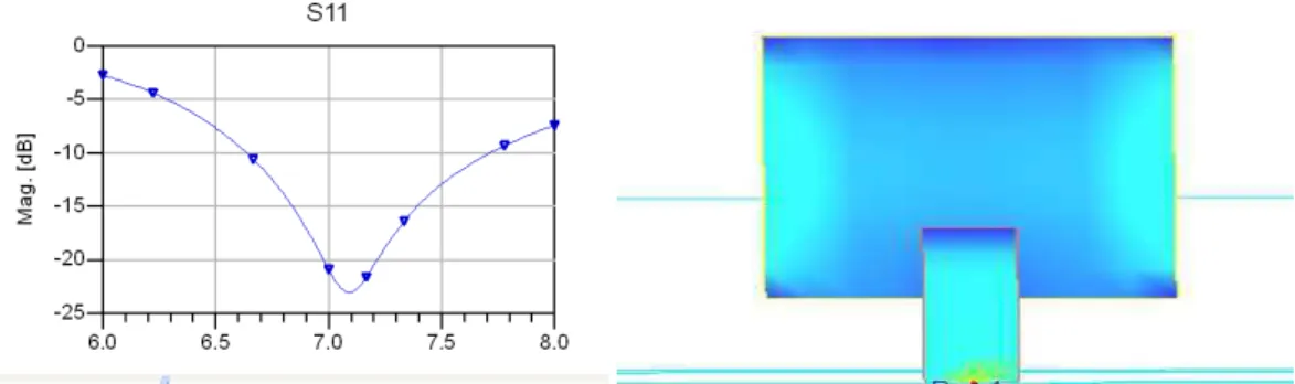
Figure 5- return loss at the resonant frequency Figure.6. Current plot of designed patch
After simulation we have achieved a total power radiation is 2.48752mw.
Figure.7. Antenna parameters from Momentum (ADS)
Bandwidth Enhancement In Multilayer Microstrip Proximity Coupled Array
Figure.10. Cartesian plot of Field in Theta Plane Figure.11. Cartesian plot of Field in Phi Plane
Analysis of Proximity Coupled Microstrip Antenna Results:
In this paper a proximity coupled antenna has been successfully designed with calculating all the parameters required for the particular frequency requirement. Its simulation on ADS is done, parameters are optimized.
The results obtained are
Frequency: 7.08 GHz, Return loss: -23 dB, Gain: 8.77248 dB, Directivity: 8.77376 dB
But now we go with Microstrip antenna arrays because they are very popular for their low profile and light weight as well as their flexibility. The major advantage of Microstrip array antenna is the increased gain and directivity.
6. Simulation of Proximity-Coupled Microstrip Array Antenna Analysis of ADS Momentum Results:
IJECSE,Volume1,Number 2
Shubham Gupta and Shilpa Singh
Figure.14. Current plot of designed patch Figure.15. Antenna parameters from Momentum (ADS)
Figure.16. Polar plot of Theta Plane Figure.17. Polar plot of Phi Plane
Figure.18. Cartesian plot of Field in Theta Plane Figure19. Cartesian plot of Field in Phi Plane
Bandwidth Enhancement In Multilayer Microstrip Proximity Coupled Array
A Proximity coupled microstrip array antenna has been successfully designed with calculating all the parameters
required for the particular frequency requirement. Its simulation on ADS is done, parameters are optimized.
The results obtained are:
Frequency: 7.07 GHz, Return loss: -28 dB, Gain: 10.1084 dB, Directivity: 10.1088 dB
7. Conclusion
This paper has presented for increasing the bandwidth and directivity we should use the multilayer proximity coupled antenna. Using this technique we have also improved the directivity of antenna which is highly desirable for high performance fighter aircraft. For achieving the highly directional antenna we have designed an array of proximity coupled antenna and achieved a bandwidth of 19% and directivity 10.1088dB which is far more better than a proximity coupled antenna single element having bandwidth of 14.77% and directivity 8.77376dB.
References
[1] K. R. Carver and J. W. Mink, “Microstrip antenna technology,” IEEE Trans. Antennas And Propagation., vol. AP-29, pp. 2-24, Jan. 1981. [2] Constantine A. Balanis, Antenna Theory Analysis and Design. New York: John Wiley and Sons, 2nd 1997.
[3] Gary Breed, Editorial Director, “The Fundamentals of Patch Antenna Design and Performance”, From March 2009 High Frequency Electronics, Copyright © 2009 Summit Technical Media, LLC.
[4] Neeraj Rao and Dinesh Kumar V.” Gain and Bandwidth Enhancement of a Microstrip Antenna Using Partial Substrate Removal in Multiple-layer Dielectric Substrate” Progress In Electromagnetics Research Symposium Proceedings, Suzhou, China, Sept. 12-16, 2011. [5] Nader Behdad, “ADS Momentum Tutorial No. 1, Rev. 1”, EEL 6463, spring 2007, (.ucf.edu"[email protected])
[6] Vivekananda Lanka Subrahmanya, “Pattern Analysis of “The Rectangular Microstrip Patch Antenna”, Final Master’s Degree Thesis, University College of Boras School of Engineering.
[7] Ramesh Garg, Prakash Bhartia, “ Microstrip Antenna Design Handbook”, Artech House, London.
[8] Ali A. Dheyab Al-Sajee and Karim A. Hamad” Improving Bandwidth Rectangular Patch Antenna Using Different Thickness Of Dielectric Substrate” ARPN Journal of Engineering and Applied Sciences, Vol. 6, No. 4, April 2011.
[9] Kin-Lu Wong, Design of Nonplanar Microstrip Antennas and Transmission Lines, John Wiley & Sons, Inc., 1999.
[10] D. M. Pozar and B. Kaufman, “Increasing the bandwidth of a microstripantenna by proximity coupling,” Electron. Lett., vol. 23, no. 8, pp.368–369, Apr. 1987.
[11] J. P. Daniel, M. Himdi, and D. Thouroude, “Printed Antenna Arrays: Examples of Commercial Applications”,IEEE-APS conference on, Antennas and Propagation for Wireless Communications, 1998, pp. 105-108 .
[12] A. Sabban, E. Navon ” A MM-Waves Microstrip Antenna Array”, IEEE Symposium, Tel-Aviv,March 1983.
[13] Kazi Tofayel Ahmed1, Md. Bellal Hossain1, Md. Javed Hossain1“Designing a high bandwidth Patch Antenna and comparison with the former Patch Antennas”Canadian Journal on Multimedia and Wireless Networks Vol. 2, No. 2, April 2011.