ENERGETIC AND EXERGETIC ANALYSES OF CARBON DIOXIDE
TRANSCRITICAL REFRIGERATION SYSTEMS FOR HOT CLIMATES
by
Farivar FAZELPOUR
Department of Energy System Engineering, Islamic Azad University – South Tehran Branch, Tehran, Iran
Original scientific paper DOI: 10.2298/TSCI121007026F
In the last two decades many scientific papers and reports have been published in the field of the application of the CO2as a refrigerant for refrigeration systems and
heat pumps. Special attention has been paid to the transcritical cycle. However, al-most no papers discussed such cycles for hot climates, i. e., when the temperature of the environment is higher than 40 ºC during a long period of time. This paper deals with the energetic and exergetic evaluation of a CO2refrigeration system operating
in a transcritical cycle under hot climatic conditions. The performance and exergy efficiency of the CO2refrigeration system depend on the operation conditions. The
effect of varying these conditions is also investigated as well as the limitations asso-ciated with these conditions.
Key words: refrigeration system, carbon dioxide, transcritical cycle, energy
analysis, exergy analysis, hot climatic conditions
Introduction
The application of carbon dioxide (CO2) for refrigeration is known from the middle of the 19thcentury, including operation based on a transcritical cycle. From the middle of 1920's
until the middle of 1980's this refrigerant was out of the interest of scientists and practical engi-neers because of the (a) grooving interest to the newly introduced artificial refrigerants (CFC and HFC refrigerants, or so-called “freons”) due to their advantages compared with the “old” re-frigerants, and (b) technical limitations related to the large practical application of CO2. In the 1990's the interest to the so-called “natural refrigerants” (CO2, ammonia, NH3, propane, butane, and water) was renewed, especially for CO2, due to considerations related to ozone depletion potential (ODP) and global warming potential (GWP), which have restricted the use of CFC and HFC refrigerants [1]. CO2has some unique properties that make this refrigerant completely dif-ferent than other “natural refrigerants”. The technical developments during the last decades helped overcome many of the barriers for the wide application of CO2, but still we need to inves-tigate the rational application of this attractive refrigerant.
A large number of scientific publications related to the theoretical and practical inves-tigations of the different refrigeration and heat pump systems using CO2followed after publica-tion of the papers published by Lorentzen (for example, [2, 3]). In the 2000s we already had
eral papers [4-6], where very good detailed reviews of many publications have been reported. However, in all these publications only European (mainly Northern European) climatic condi-tions are considered for the operation of refrigeration and heat pump systems.
The Middle East is an interesting region of the world to study because this region has experienced impressive increases in economic growth, and energy demand [7]. For countries with hot climates, the energy consumption related to refrigeration processes is much higher than for other countries. It is caused by the expanded application of refrigeration processes (espe-cially for air conditioning systems) and by the higher temperature of the environment (tempera-ture of a cooling medium) that leads to a higher pressure ratio within the refrigeration system, and, therefore to higher energy consumption.
The operation of a CO2refrigeration system at a high temperature of the environment can be similar to the operation of a CO2heat pump. Therefore, the following publications with corresponding assumptions and results have been considered here. Neksfitet al.[8] reported op-timal values of the pressure as well as the isentropic and volumetric efficiencies of the CO2 com-pressors for heat pump applications in the range of the inlet water temperature between 7 and 20iºC and corresponding temperature of the evaporation between –25 ºC and 15 ºC, and hot wa-ter temperature between 55 and 80 ºC. In this range of temperatures, the pressure ratio is varied between 2 and 5. The isentropic efficiency of the compressor is varied between 0.81 and 0.75 and the volumetric efficiency between 0.9 and 0.78. Schmidtet al., [9] investigated the charac-teristics of high-temperature heat pumps with a transcritical CO2process for drying purposes with a maximal temperature of 60 ºC. The isentropic efficiency of the compressor was varied be-tween 0.65 and 0.7.
An interesting review of CO2heat pump systems is published by Neksa [10], however only a relative low temperature for the hot water is considered with a maximal pressure of 90 bar and a minimal pressure of 35 bar. For these operation conditions, the isentropic efficiency of the compressor was 0.92 for the pressure ratio 2.4 and 0.68 for the pressure ratio 3.2. Cecchinatoet al. [11] reported a similar heat pump system with maximal temperature of the hot water of 45 ºC. The maximal pressure within the gas cooler is assumed to be 115 bar, whereas the isentropic ef-ficiency of the compressor is varied between 0.6 and 0.63.
Yokoyamaa et al. [12] investigated the effect of ambient temperatures (inlet water temperature) on the performance of a CO2heat pump. At minimal inlet water temperature 5 to 15iºC, the maximal achieved water temperature was 60 ºC at a pressure in the gas cooler of 102.8 bar.
In the research done by Fernandezet al. [13], the operation conditions for the heat pump include a temperature of evaporation of 10 ºC, and a maximal pressure within gas cooler of 110 bar.
Zhanget al. [14] reported also experimental studies on the optimum pressure within a heat exchanger for a CO2heat pump system. The minimal temperature within the evaporator is 10iºC and the maximal pressure within the gas cooler is 125 bar. The isentropic efficiency of the compressor is in the range of 0.65 to 7.
ex-perimental results but for a CO2residential air-conditioning system. The temperature of the en-vironment was varied between 10 and 14 ºC. The information about the pressure in the gas cooler is missed. The results are: 30% of the total exergy destruction takes place within the ex-pansion valve, 19% within the compressor, 31% within the gas cooler, and 20% within the evap-orator. Srinivasanet al. [17] used an exergy analysis as an application for a newly developed fundamental equation of state for CO2. The exergy analysis is conducted in the wide range of the evaporation temperature between –20 ºC and 10 ºC and pressure ratio between 2 and 10. The temperature of the environment is assumed to the equal to 40 ºC. The value ofCOPvaries be-tween 0.95 and 1.8 and the exergy efficiency bebe-tween 0.07 and 0.17. Fartajet al. [18] reported entropy generation and exergy analyses for the comparison of transcritical CO2and subcritical R134a refrigeration cycles. For the CO2cycle the minimal pressure within the evaporator is 42 bar (temperature is around 9 ºC), and within the gas cooler 111.3 bar. The reported exergetic variables for the components are doubtful because clear definitions are not given. The overall exergy efficiency is 0.34.
Sarkaret al.[19] discussed an exergy analysis for transcritical CO2heat pump systems with focus on the heat transfer and fluid flow effects. The temperature of the environment is as-sumed to be 40 ºC. The variation in the isentropic efficiency of the compressor between 0.5 and 0.8 leads to a variation of the exergy efficiency of the overall system between 0.21 and 0.37. In all mentioned publications the exergy analysis was conducted in the term of “exergy in-let/exergy outlet” based on the methodology given by Kotas [20].
The goal of this research is the energetic and exergetic investigation of a transcritical CO2refrigeration system for hot climates, particularly for the Middle Eastern countries.
Schematic and simulation
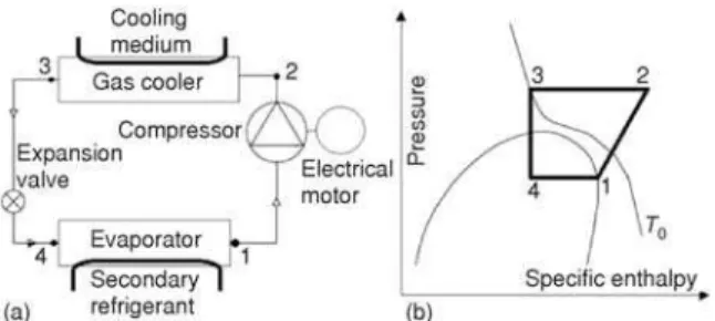
In this paper a simple CO2 transcritical refrigeration system (fig. 1) is studied. The temperature of evaporation is assumed to be –10 ºC (industrial storage of a wide range of food products). The environmental temperature,i. e. the minimal temper-ature of cooling medium for the gas cooler is assumed to:
– be 25 ºC as a reference condition for Europe (as in many already mentioned publications), and – vary between 35 ºC and 60 ºC.
A simple CO2 transcritical refrigeration system can also contain an internal heat exchanger and/or a semi-hermetic compressor.
Many factors affect the performance of a CO2refrigeration system, for example: – for the compressor
– isentropic efficiency of the compressor,
– maximal pressure at the outlet of the compressor,
– maximal temperature at the outlet of the compressor (related to the thermal stability and non-flamability of a lubricant),
– superheating of the refrigerant within the electrical motor (if a semi-hermetic compressor is used),
– for the gas cooler
– pressure drop within the gas cooler,
– temperature difference between refrigerant at outlet of the gas cooler and temperature of the cooling medium,
– for the evaporator
– temperature difference within the evaporator, – pressure drop within the evaporator,
– superheating of the refrigerant within the evaporator, and
– temperature difference within the internal heat exchanger (if this component is used). The following information was obtained from publications by other authors and from data of companies producing equipment for CO2transcritical refrigeration systems, for example [21-25]:
– The efficiency of the CO2refrigeration system strongly depends on the pressure ratio in the
compressor (simple system or with internal heat exchanger); the effect of including an internal heat exchanger is negligible.
– The superheating process within the evaporator (in the range between 0 and 10 K) does not affect the overall efficiency; a similar conclusion is obtained for the superheating of the refrigerant within the electrical motor of a semi-hermetic compressor.
– The temperature at the outlet of the compressor is, in general, not limited, when synthetic lubricants are used.
– The pressure within the gas cooler depends on the limitations for the compressors. The following information was obtained from refrigeration companies: “Bock” [23] and “Bitzer” [24] pEVmax= 100 bar and p
GCmax= 150 bar; “Adson – Engineering Corporation” [25] –pEVmax= = 40 bar and pGCmax = 135 bar.
The following assumptions were made for the simulations: – State 1 is saturated vapor.
– The temperature at state 3 is equal to the minimal temperature of the cooling medium (T0).
– The cooling medium is unknown and the design of the gas cooler is not
specified, therefore, for simplification we can consider only an average temperature for the cooling medium,Tcma =T +
0 5 K.
– The secondary refrigerant is also unknown and the design of the evaporator is also not specified, therefore, for simplification we can consider only an average temperature for the secondary refrigerant,Tsra T
EV
= +5 K.
– The pressure drop within the evaporator is assumed to be 0.75 bar and within the gas cooler 3 bar. – The isentropic efficiency of the compressor is equal to 0.8 and the efficiency of the electrical
motor is equal to 0.88.
– For the sensitivity analysis the isentropic efficiency of the compressor is varied between 0.7 and 0.85.
For the simulation of the CO2refrigeration systems the software CoolPack [26] was used.
Evaluation
Energetic evaluation
The model for the energetic evaluation of the CO2transcritical refrigeration system consists on the following equations (fig. 1):
– specific heat of evaporation
– specific work of the compression process
wCM =h2 -h1 (2)
– specific heat for gas cooling
qGC=h2 -h3 (3)
– mass flow rate of CO2
& &
m Q
q CO EV
EV
2 = (4)
– power of the compressor
& & WCM wCMmCO
2
= (5)
– power of the electrical motor
& & WEM WCM
EM
= h
(6)
– gas cooler heat rate
& & QGC qGCmCO
2
= (7)
– COP
COP Q W = &
& EV
EM
(8a)
However, in many publications the value ofCOPis calculated as:
COP Q W = &
& EV
CM
(8b)
The CO2 refrigeration system can be optimized from the thermodynamic point of view:W&CM ®minby keepingQ&EV =const.
Exergetic evaluation
An exergy analysis identifies the location and magnitude of the thermodynamic ineffi-ciencies [27-29]. Exergy is the maximum theoretical useful work (shaft work or electrical work) obtainable from a system during a process that brings this system into equilibrium with the ther-modynamic environment (temperatureT0and pressurep0) while interacting only with this envi-ronment [28]. The exergy of the systemEsysconsists of four main components: Physical exergy, chemical exergy, kinetic exergy, and potential exergy:
E EsysPH E E E
sys = + CH + KN + PT (9)
Usually, the potential and kinetic exergy changes can be neglected. For compression refrigeration systems, the chemical exergy can also be neglected. Physical exergy is the maxi-mum theoretical useful work obtainable as the system passes from its initial state (T,p,x) to the restricted dead state (T0,p0,x) while heat transfer takes place only between the system and the environment. Physical exergy for a material stream is:
EPH =me& PH =m h&[( -h )-T s( -s )]
0 0 0 (10)
However, for refrigeration systems, the physical exergy of material streams can be fur-ther split into a fur-thermal part and a mechanical part [30]:
The exergy analysis is based on exergy balances written for the overall system:
& & & &
E E E E
k
F, tot = P, tot +å D, k + L, tot (12a)
and for each component of the system:
& &
EF, k =EP, k +ED, k (12b)
For the simple CO2transcritical refrigeration systemE&F, tot =W&EM,E&P, tot =E&P,EVand
& &
EL, tot =EP,GC (exergy transport to the environment [27, 28]). The fuel and product of each com-ponent is given by the equations:
– compressor E&F,CM =W&CM andE&P,CM =E&2 -E1, – electrical motor E&F,EM =W&EM andE&P,EM =W&CM, – gas cooler E&F,GC=E&2 -E&3 andE&P,GC=Q&GC(1-T0/Tcma),
– expansion valve E&F,EXV E&3M E& 4M
= - andE&F,EXV E&4T E& 3T
= - ,
– evaporator E&F,EV =E&4 -E&1andE&P,EV =Q&EV(1-T0/Tsra).
The exergy destruction in thek-th component isE&D, k =E&F, k-E&P, k. The exergy destruction ratio for thek-th component is:
y E
E k
D, k
D, tot
= &
& (13)
The exergy efficiency of the overall refrigeration systems is:
etot P, tot F, tot
= &
& E
E (14)
For the exergy analysisT0is equal to the minimal temperature of the cooling medium andp0=1 bar.
Results
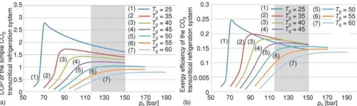
Figure 2 demonstrates the values ofCOPandetotfor different assumed temperaturesT0 in order to estimate the optimal pressure within the gas cooler. The character ofCOPcurves ob-tained here is qualitatively similar to the data reported by Kauf [21],i .e. flat character of theCOP functions forT0> 40 ºC andCOP< 1 forT0> 50 ºC. With increasing temperature of the environ-ment, the optimal value of the pressure in the gas cooler increases (tab. 1). Taking into account the equipment limitations associated with the pressure at the outlet of the compressor, we can con-clude, that for the rangeT0= 34 to 50 ºC the possibility to optimize the system thermodynamically
Figure 2.COPand exergy efficiency (e
is limited (shaded zone in fig. 2) and forT0> 50 ºC we cannot achieve thermodynamically optimal op-eration conditions.
For European operation conditions (T0 is around 25 ºC) the value ofCOPat optimal opera-tion condiopera-tions is around 2.7. With increasing tem-perature of the environment in hot climates – as-sumingT0> 40 ºC, the values ofCOPtend to 1 or even lower. This makes less attractive the use of CO2transcritical refrigeration systems for hot cli-mates; however a one-stage compression process is practically possible for both European operation conditions and hot climates operation conditions
becausep2/p1= 2.72 forT0= 25 ºC andp2/p1= 7.0 forT0= 60 ºC [23-25].
Figure 3 shows two characteristics of the thermodynamic cycle that are usually not re-ported in the literature: (a) The temperature at the outlet of the compressor, fig. 3(a) and (b) mass flow rate of the refrigerant, fig. 3(b). Based on data from [24], forpGCopt > 120 bar, problems with the lubricant may arise,i. e., the standard lubricants for the CO2transcritical refrigeration sys-tems should be replaced with special ones adapted to the higher pressures.
It is obvious that during the operation the value of pGCopt cannot be kept constant. Small variations always take place. Based on data in fig. 2, two values of pressure ratio (p< pGCopt andp> pGCopt) correspond to the same value of theCOPoretot. The question is: which value is preferable if pGCopt is not used. To answer this question we should consider the value of the mass flow rate of the refrigerant. This value affects the power supplied to the com-pressor as well as the size and, therefore, the cost of the components. Thus, the value of
&
mCO2should be as small as possible. Figure
3(b) demonstrates the interdependences be-tweenpGCandm&CO2 for different values ofT0.
For all values ofT0, the mass flow rates of the refrigerant drop significantly during increas-ing pGC until the optimum value pGCoptis achieved, and after that become almost con-stant forpGC> pGCopt. Therefore, the casep>
pGCopt is better for practical applications. The exergy analysis shows that the exergy efficiency is relative low and it varies be-tweenetot= 0.25 forT0= 25 ºC andetot= 0.14 forT0= =i60 ºC. The values ofetotreported in other publications are higher because a differ-ent definition of the exergy efficiency was used there.
Table 1. Optimal pressure in the gas cooler
Temperature of the environment,T0[ºC]
Optimal pressure, pGCopt[bar]
25 70
35 95
40 110
45 125
50 140
55 160
60 180
The influence of the isentropic efficiency of the compressor is studied using exergy analysis. Figure 4(a) shows the values ofetotas a function ofhCM(hCM = 0.7 to 0.85), and fig. 4(b) shows how the isentropic efficiency of the compressor affects the total exergy destruction within the overall refrigeration system. The reader can see that the curves ofetotare almost parallel, but the curves ofE&D, tot diverge at higherT0values.
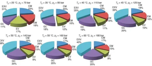
Finally the values of the exergy destruction ratios (yk) are given as a function ofT0at the opti-mal pressure in the gas cooler (fig. 5). With in-creasing temperature of the environment (T0) the ratio of exergy destruction within the compressor decreases from 23% down to 17%, whereas the ratio for the electrical motor almost remains con-stant, for the evaporator decreases from 17% down to 9%, for the gas cooler increases from 11% up to 20%, and for the expansion valve in-creases from 31% up to 39%. Based on these data we can conclude that in order to improve the CO2 transcritical refrigeration system especially for hot climates we should focus on the irreversibilities within the expansion valve. As we know, this process cannot be improved by it-self, therefore the structure of the refrigeration system and/or the operation conditions for other components should be modified.
Figure 4. Effect of the isentropic efficiency of the compressor on the exergy efficiency of the refrigeration systeme
tot(a) and the total exergy
destructionE&D, tot (b)
Figure 5. Exergy destruction ratios for the different operation conditions of the CO2 transcritical
Conclusions
In this paper the transcritical CO2refrigeration system is evaluated based on energetic and exergetic criteria. Special attention is given to the operation conditions for this system in hot climates,i. e. when the temperature of the environment is higher than 40 ºC. The optimal pres-sure in the gas cooler is defined for each considered value ofT0assuming that the temperature of the generated cold remains constant (–10 ºC). The analysis of the optimal pressure in the gas cooler and the limitations associated with the pressures for modern available compressors for transcritical CO2refrigeration systems demonstrate that optimal operation conditions cannot al-ways be achieved. Based on exergetic evaluations, a very important conclusion in obtained. The most important issue for the improvement of the transcritical CO2refrigeration system is to find an engineering solution for decreasing the exergy destruction (irreversibilities) within the ex-pansion valve. In this way the transcritical CO2refrigeration system will become also attractive for the countries with hot climates. Further work will focus on the economic evaluation of the transcritical CO2refrigeration system.
Acknowledgments
The author wish to thank the Islamic Azad University – South Tehran Branch for the financial support of this work (project B/16/90644).
References
[1] ***, United Nations Environment Programme (UNEP), Montreal Protocol on Substances that Deplete the Ozone Layer, 1987
[2] Lorentzen, G., Pettersen, J., A New Efficient and Environmentally Benign System for Car Air-Condition-ing,International J Refrigeration, 16(1993), 1, pp. 4-12
[3] Lorentzen, G., Revival of Carbon Dioxide as a Refrigerant,International J Refrigeration, 17(1994), pp. 292-300
[4] ***, 15thInformatory Note on Refrigerants, Carbon Dioxide as a Refrigerant, Paris, France, 2000
[5] Pearson, A., Carbon Dioxide – New Uses for an Old Refrigerant, Review,International J Refrigeration, 28(2005), 8, pp. 1140-1148
[6] Kim, M.-H.,et al., Fundamental Process and System Design Issues in CO2Vapor Compression Systems,
Progress in Energy and Combustion Science, 30(2004), 2, pp. 119-174
[7] Sadorsky, P., Trade and Energy Consumption in the Middle East,Energy Economics, 33(2011), 5, pp. 739-749
Nomenclature
COP – coefficient of performance, [–] &
E – exergy rate, [MW] e – specific exergy, [kJkg–1]
h – specific enthalpy, [kJkg–1]
&
m – mass flow rate, [kgs–1]
p – pressure, [MPa] &
Q – heat rate, [MW]
s – specific entropy, [kJkg–1K–1]
T – temperature, [ºC] &
W – power, [MW]
0 – reference state for the exergy analysis
Greek symbols
e – exergy efficiency, [–] h – isentropic efficiency, [–]
Aronyms
CM – compressor EM – electrical motor EV – evaporator EXV – expansion valve GC – gas cooler
Subs- and superscripts
a – average cm – cooling medium D – exergy destruction F – fuel
[8] Neksfit, P.,et al., CO2-Heat Pump Water Heater: Characteristics, System Design and Experimental
Re-sults,International J Refrigeration, 21(1998), 3, pp. 172-179
[9] Schmidtt, E. L.,et al., Applying the Transcritical CO2Process to a Drying Heat Pump,International J
Re-frigeration, 21(1998), 3, pp. 202-211
[10] Neksa, P., CO2Heat Pump Systems,International J Refrigeration, 25(2002), 4, pp. 421-427
[11] Cecchinato, L.,et al., Carbon Dioxide as Refrigerant for Tap Water Heat Pumps: A Comparison with the Traditional Solution,International J Refrigeration, 28(2005), 8, pp. 1250-1258
[12] Yokoyamaa, R.,et al., Influence of Ambient Temperatures on Performance of a CO2Heat Pump Water
Heating System,Energy, 32(2007), 4, pp. 388-398
[13] Fernandez, N.,et al., Comparison of CO2Heat Pump Water Heater Performance with Baseline Cycle and
Two High COP Cycles,International J Refrigeration, 33(2010), 3, pp. 635-644
[14] Zhang, X. P.,et al., Theoretical and Experimental Studies on Optimum Heat Rejection Pressure for a CO2
Heat Pump System,Applied Thermal Engineering, 30(2010), 16, pp. 2537-2544
[15] Bilgen, E., Takahashi, H., Exergy Analysis and Experimental Study of Heat Pump Systems,International J Exergy, 2(2002), 4, pp. 259-265
[16] Tao, Y. B.,et al., Exergetic Analysis of Transcritical CO2Residential Air-Conditioning System Based on
Experimental Data,Applied Energy, 87(2010), 10, pp. 3065-3072
[17] Srinivasan, K.,et al., Exergetic Analysis of Carbon Dioxide Vapour Compression Refrigeration Cycle Us-ing the New Fundamental Equation of State,Applied Energy, 44(2003), 20, pp. 3267-3278
[18] Fartaj, A.,et al., Second Law Analysis of the Transcritical CO2Refrigeration Cycle,Energy Conversion &
Management, 45(2004), 13-14, pp. 2269-2281
[19] Sarkar, J.,et al., Transcritical CO2Heat Pump Systems: Exergy Analysis Including Heat Transfer and
Fluid Flow Effects,Energy Conversion & Management, 46(2005), 13-14, pp. 2053-2067
[20] Kotas, T. J.,The Exergy Method of Thermal Plant Analysis, Krieger Publishing Company, Malabar, Fla., USA, 1985
[21] Kauf, F., Determination of the Optimum High Pressure for Transcritical CO2-Refrigeration Cycles,
Inter-national J Thermal Sciences, 38(1999), 4, pp. 325-330
[22] Rozhentsev, A., Wang, C.-C., Some Design Feature of a CO2Air Conditioner,Applied Thermal
Engineer-ing, 21(2001), 8, pp. 871-880 [23] ***, Bock, http://www.bock.com [24] ***, Bitzer, http://www.bitzer.de
[25] ***, Adson – Engineering Corporation, http://www.adsoncompressors.com
[26] ***, Cool Pack. Version 1.46. Department of Mechanical Engineering, University of Denmark, http://www.et.dtu.dk/coolpack.
[27] Bejan, A.,et al.,Thermal Design and Optimization, John Wiley and Sons, New York, USA, 1996 [28] Tsatsaronis, G., Definitions and Nomenclature in Exergy Analysis and Exergoeconomics,Energy, 32
(2007), 4, pp. 249-253
[29] Tsatsaronis, G., Recent Developments in Exergy Analysis and Exergoeconomics,International J Exergy, 5(2008), 5/6, pp. 489-499
[30] Morosuk, T., Tsatsaronis, G., Advanced Exergetic Evaluation of Refrigeration Machines Using Different Working Fluids,Energy, 34(2009), 12, pp. 2248-2258
![Table 1. Optimal pressure in the gas cooler Temperature of the environment, T 0 [ºC] Optimal pressure,p GCopt [bar] 25 70 35 95 40 110 45 125 50 140 55 160 60 180](https://thumb-eu.123doks.com/thumbv2/123dok_br/18356128.353602/7.892.456.743.602.1029/table-optimal-pressure-cooler-temperature-environment-optimal-pressure.webp)