Abstract—This paper proposes a new Frequency Selective Surface (FSS) with modifications on the Jerusalem Cross (JC) geometry to provide a multiband response. Fractal levels are created by introducing concentric self-similar JC copies in the original unit cell. This modification results in new dipoles at the structure which allows for the appearance of new bands proportional to these diploles’ lengths, while maintaining total unit cell size. Three fractal levels of the JC FSS are studied in this paper, and third level presents five resonant frequencies which are
f1=1.78 GHz, f2=6.42 GHz, f3=8.69 GHz, f4=10.94 GHz and f5=12.98
GHz. Simulation results for the insertion loss (S21), surface current distribution and measurement results are presented.
Index Terms—Frequency Selective Surface, Jerusalem Cross, Multiband
Response, Fractal.
I. INTRODUCTION
Recently, interest in the potential application of fractal geometries has increased. Some fractal shapes are highly convoluted geometries, giving the possibility to embed resonant elements into small areas. In some applications, self-similarity [1, 2] property of certain fractals can be exploited to create multi-resonant behavior [3]. The self-similarity can be described as the replication of the geometry of the initial element with different scale in the same structure [4].
This paper proposes the use of fractal characteristics to design a set of four orientation insensitive (OI) multi-band Frequency Selective Surfaces (FSSs). FSSs are bi-dimensional structures, composed by periodic arrays of metallic elements that are printed on one or more dielectric substrates [5]. When an incident electromagnetic wave encounters a FSS, resonance effects can occur on the grid elements in a given frequency band, depending on the elements’ geometry and periodicity, and the properties of the dielectric substrate [5]. For some frequencies, the induced currents in the cells are constructive and all incident power is transmitted through the structure [6].
H. V. H. Silva Filho¹†, C. P. N. Silva¹, M. R. T. de Oliveira¹, E. M. F. de Oliveira¹,², M. T. de Melo¹,
T. R. de Sousa³ and A. Gomes Neto³.
1-Departamento de Eletrônica e Sistemas, Universidade Federal de Pernambuco, Recife, Brazil 2-Unidade Acadêmica do Cabo de Santo Agostinho, Universidade Federal Rural de Pernambuco,
Cabo de Santo Agostinho, Brazil
3-Instituto Federal de Educação, Ciência e Tecnologia da Paraíba, João Pessoa, Brazil.
†Corresponding Author: [email protected]
diplexers, dichroic surfaces for reflectors and large aperture antennas’ subreflectors and absorbers [7-10]. Fractal geometries have been extensively implemented in the design of multiband antennas and FSSs.
This paper investigates the behavior of a modification in the Jerusalem Cross FSS (JC-FSS) [11-13]. This modification consists in replicating the JC geometry in different scales to provide a multiband structure without changing the area occupied by the primary structure, hereby called Modified Jerusalem Cross Frequency Selective Surface (MJC-FSS). These modifications present auto-similarity fractal characteristics where each fractal level consists in adding a rescaled JC geometry. It is presented structures for three fractal levels. The third level presents five resonant frequencies which are f1=1.78 GHz, f2=6.42 GHz, f3=8.69 GHz, f4=10.94 GHz and f5=12.98 GHz.
These frequencies of the Multiband FSS have applications in satellite communication [14], electromagnetic absorbers used in panels for blocking wireless signals and shielding internal environments [15,16], passive RFID chips based on multiband FSS [17] and reflectors for antennas operating in the S and Ku band [18,19]. The simulation results for insertion loss (S21) and surface
currents distribution were obtained using CST Microwave Studio software 2016®.
II. DESCRIPTIONOFSTRUCTURES
III. JERUSALEM CROSS FSS
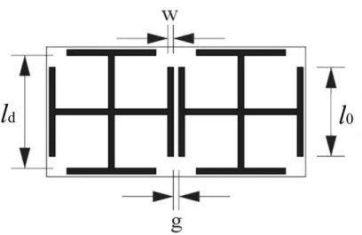
Fig. 1 shows two unit cells of the JC-FSS. This geometry consists of a central cross-dipole with length ld and dipoles placed perpendicularly at the end of each dipole with length l0. The unit cells are
separated by a distance g, and all dipoles have a width w. The unit cell is a patch element, thus the
black region represents the metallic part of the structure. This structure presents a stop band response because the FSS contains patch elements.
The JC-FSS presents dual stop-band frequency response and orientation-insensitiveness (resonance occurs for both vertical and horizontal polarizations) due to its symmetrical geometry [6]. The first resonant frequency is mainly caused by the cross dipole with length ld, as well as the second
resonant frequency is related to the perpendiculars dipoles with length l0.
A. Modified Jerusalem Cross
The proposed unit cells of the modified JC-FSS (MJC-FSS) are shown in Fig. 2. The Fig. 2(a) shows the first fractal level of this modification. It consists in inserting a rescaled concentric JC-FSS inside of the original JC-FSS. This results in the appearance of dipoles with the same orientation of the original dipoles. These new dipoles have length l2, slightly smaller than l1, and they are separated
by a distance d. For the other fractal levels, the same procedure is carried out. Fractal levels 2 and 3
are shown in Fig. 2(b) and 2(c).
This procedure gives the structure fractal characteristics because of its self-similarity. Other parameter that indicates the fractal characteristics is the fractal dimension [1, 3]. When the fractal dimension is non-integer, the geometry can be classified as a fractal [20]. According to the box counting method [1, 3], the fractal dimension for the third interaction of the MJC-FSS is non-integer and approximately 1.5, which indicates that the structure can be fractal.
Fig .2 MJC-FSS geometry unit cells, (a) fractal level 1; (b) fractal level 2; and (c) fractal level 3.
In the JC-FSS, the cross dipole is responsible for the first resonant frequency and the perpendicular dipoles for the second one; therefore, it is expected that the new dipoles result in the appearance of new resonant frequencies. This way, the first fractal level, shown in Fig. 2(a), is expected to present three resonant frequencies, the second fractal level, shown in Fig. 2 (b), should present four resonant frequencies and the third fractal level, shown in Fig. 2(c), should present five resonant frequencies.
The traditional JC-FSS and the fractal levels of MJC-FSS studied here were designed according to the dimensions: ld = 20.5, l0 = 16.1, l1 = 11.2, l2 = 8.96, l3 = 7.16, w = 1, d = 1 and g = 1 mm. Each
IV. RESULTS AND DISCUSSION
A. Insertion Loss (|S21|)
This section presents the measured and simulated results for the proposed FSSs considering a normal incidence angle of a plane wave.
In order to validate the simulations, a 9x9 array of the JC-FSS and of the three fractal levels of the MJC-FSS were fabricated as shown in Fig. 3. The substrate used was FR-4 (h = 1 mm, r = 4,4, tan = 0.02) with dimensions of 20 cm x 20 cm.
Fig. 3 Photograph of the FSS prototypes: (a) JC-FSS, (b) fractal level 1, (c) fractal level 2 and (d) fractal level 3.
Fig.4 Measurement setup.
Fig.5 (a) shows the simulated and measured results of S21 for the JC-FSS for normal incident
angle. As expected, two resonant frequencies appear as mentioned in previous section
Fig. 5 Simulated and measured results of the (a) JC-FSS; (b) MJC-FSS first fractal level; (c) MJC-FSS second fractal level;
(d) MJC-FSS third fractal level.
(a) (b)
insertion of the rescaled JC in the FSS provides a new resonant frequency due the dipole l1. Fig. 5 (c)
and 5(d) present the second and third fractal level results, respectively. As it is shown, the addition of self-similarity JC at each fractal level results in the appearance of new resonant frequencies.
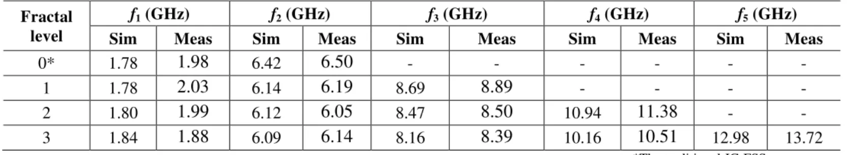
The Table 1 summarizes the simulated and measured resonant frequencies. Because of coupling effects, the resonant frequency of a dipole can be shifted when a new dipole is inserted. However, on this design, these shifts were small. When new dipoles were inserted, the f1 had a maximum shift of
2.5%, f2 had a maximum shift of 4.7%, f3 had a maximum shift of 4.3% and f4 had a maximum shift of
7.6% considering the measured values. These small shifts indicate that the coupling between the dipoles is low; therefore, an independent control of frequency in each fractal level is possible.
Comparing the simulated and measured results at the third fractal level, there was a shift of 2.7% at the first resonant frequency, 0.8% at the second resonant frequency, 2.8% at the third resonant frequency, 3.4% at the fourth resonant frequency, 5.7% at the fifth resonant frequency. A good agreement is observed between measured and simulated results. The shift at the f1, f4 and f5 can be
attributed to the small gain of the horn antennas used to measure this frequency bands and to standing wave effects.
Papers [21-23] also investigate fractal FSSs. In [21], the proposed fractal FSS provides only one resonant band. In [22,23], FSSs fractal based on Sierpinski and Cross dipole presented three resonant bands spaced by scalar factor of two, which is determined by the FSS geometry. The structure developed in this paper is able to achieve five or more bands which can be easily adjusted varying the dipoles length.
Table 1 Measured and simulated resonant frequency characteristics.
Fractal level
f1 (GHz) f2 (GHz) f3 (GHz) f4 (GHz) f5 (GHz)
Sim Meas Sim Meas Sim Meas Sim Meas Sim Meas
0* 1.78
1.98
6.426.50
- - --1 1.78
2.03
6.146.19
8.698.89
- - --2 1.80
1.99
6.126.05
8.478.50
10.9411.38
--3 1.84
1.88
6.096.14
8.168.39
10.1610.51
12.98 13.72*The traditional JC-FSS
B. Measurements for incident wave angle sensitivity test
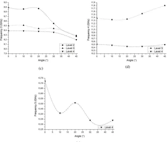
Comparing the incident angle of 45º and normal incidence at the third fractal level, there is a shift of 6.3% at the first resonant frequency, 7.1% at the second resonant frequency, 2.26% at the third resonant frequency, 0.1% at the fourth resonant frequency and 2.7% at the fifth resonant frequency. As the frequency shift is small when the plane wave incident angle is varied, the structures have a good angular stability.
Fig. 6 Measured results for different incident angles of the plane wave. (a) JC-FSS; (b) FSS first fractal level; (c)
MJC-FSS second fractal level; (d) MJC-MJC-FSS third fractal level.
(a) (b)
(a) (b)
Fig. 7 Resonant frequency as a function of incident angle. (a) 1st resonant frequency; (b) 2nd resonant frequency; (c) 3rd
resonant frequency; (d) 4th resonant frequency; (e) 5th resonant frequency;
C. Current Distribution
Fig. 8 shows the current distribution for all the resonant frequencies of the fractal level 3 of MJC-FSS for vertical polarization. The regions with the darker colors indicate where there is a greater concentration of current. It is observed that in 1.85 GHz, the current induced in the central dipole is more intense, meaning that it is the main responsible structure for this resonant frequency (Fig. 8a). The same analysis is done for the other frequencies as shown in Figure 8(b), 8(c), 8(d) and 8(e) that present the main responsible element for the resonant frequencies 6.09, 8.16, 10.16 and 12.68 GHz, respectively.
(c) (d)
Fig. 8 Simulated current distribution for the five resonant frequencies of the MJC-FSS third fractal level
CONCLUSION
[1] K. Falcone, Fractal Geometry: Mathematical Foundations and Applications, 3rd ed., John Wiley & Sons, 2013. [2] É. C. Braz and A. L. P. de S. Campos, “Multiband Frequecy Selective Surfaces with a Modified Multifractal Cantor
Geometry,” Journal of Microwaves, Optoelectronics and Electromagnetic Applicat., vol. 13, no. 2, Dec. 2014.
[3] J. Romeu, Y. Rahmat-Samii, “Fractal Elements and Their Applications to Frequency Selective Surfaces,” IEEE
Aerospace Conference Proceedings, 2000, vol.5, pp 77- 81.
[4] J. Romeu, Y. Rahmat-Samii, “Fractal FSS: a novel dual-band frequency selective surface,” IEEE transactions on
Antennas and Propagation, vol. 48, no. 7, pp. 1097- 1105, 2000.
[5] B. A. Munk, Frequency Selective Surfaces: Theory and Design, John Wiley & Sons, 2000.
[6] B. Rahmati and H. R. Hassani, “Multiband Metallic Frequency Selective Surface With Wide Range of aBand Ratio,”
IEEE Transactions on Antennas and Propagation, vol. 63, no. 8, Aug., 2015.
[7] M. Yan et. al., “A tri-band, highly selective, band-pass FSS using cascaded multi-layer loop arrays,” IEEE Transactions
on Antennas and Propagation, vol. 64, no. 5, may, 2016.
[8] D. Singh, A. Kumar, S. Meena and V. Agarwala., “Analysis of Frequency Selective Surfaces for Radar Absorbing Materials,” Progress Electromagnetics Research B, vol. 38, pp. 297-314, 2012.
[9] H. So, A. Ando, T. Sugiyama, and K. Cho, “Design for Suppressing Undesired Reflections from Frequency-Selective
Surfaces Employed in Multiband Sector Antenna,”2015 IEEE International Symposium on Antennas and Propagation
& USNC/URSI National Radio Science Meeting, Vancouver, BC, 2015, pp. 824-825.
[10] C. Ratnaratorn, C. Mahatthanajatuphat and P. Akkaraekthalin, "Gain enhancement for multiband antenna with frequency selective fractal surface reflector," 2014 Asia-Pacific Microwave Conference, Sendai, Japan, 2014, pp. 714-716.
[11] R. J. Langley and A. J. Drinkwater, "Improved empirical model for the Jerusalem cross," in Microwaves, Optics and
Antennas, IEE Proceedings H, vol. 129, no. 1, pp. 1-6, February 1982.
[12] J. J. Liu et. al., “A Multi-mode Cavity Filter with Jerusalem Cross Structure Resonator,”Asia-Pacific Microwave
Conference Proceedings, pp 2-8, 2013.
[13] T. Manabe, K. i. Kikuchi, S. Ochiai and T. Nishibori, "Dual-polarization Jerusalem-cross slot type FSS for a submillimeter-wave band," 2015 International Symposium on Antennas and Propagation (ISAP), Hobart, TAS, 2015,
pp. 1-3.
[14] Mert KARAHAN, Ertugrul AKSOY, Yasin YAVUZ ,“ A Frequency Selective Surface Design To Reduce The Interference Effect On Satellite Communication,” 8th International Conference on Recent Advances in Space Technologies (RAST),
June 2017.
[15] Liu Hai-Tao *, Cheng Hai-Feng, Chu Zeng-Yong, Zhang De-Yong, “Absorbing properties of frequency selective surface absorbers,” Materials and Design 28, 2007.
[16] Douglas J. Kern, Douglas H. Werner, Agostino Monorchio, Luigi Lanuzza and Michael J. Wilhelm, “The Design Synthesis of Multiband Artificial Magnetic Conductors Using High Impedance Frequency Selective Surfaces,”IEEE
Transactions on Antennas and Propagation, VOL. 53, NO. 1, January 2005.
[17] Md. Aminul Islam and Nemai Chandra Karmakar,” Compact Printable Chipless RFID Systems,” IEEE Transactions on
Microwave Theory and Techniques, VOL. 63, NO. 11, NOVEMBER 2015.
[18] Jonatha M. Riglsford, Sandra Martin Benito and Andrea Vallecchi,”A Tri-band Inductive Frequency Selective Surface Sub-Reflector for Satellite Communications Systems,” The 8th European Conference on Antennas and Propagation, april 2014.
[19] Te-Kao Wu and Shung-Wu Lee,” Multiband Frequency Selective Surface with Multiring Patch Elements,” IEEE
Transactions on Antennas and Propagation, VOL. 42, NO. 11, November 1994
[20] D. Harte, Multifractals: Theory and Applications, Chapman Hall/CRC Press, Washington, D.C., 2001).
[21] A. L. P. S. Campos, E. E. C. de Oliveira and P. H. da F. Silva, “Design of Miniaturized Frequency Selective Surfaces Using Minkowski Island Fractal,”Journal of Microwaves, Optoelectronics and Electromagnetic Applications, vol. 9, no. 1, Jun. 2010.
[22] A. K. Palange, A. Sonker and S. S. Yadav, "Designing of multiband frequency selective surfaces," 2016 International
Conference on Communication and Signal Processing (ICCSP), Melmaruvathur, 2016, pp. 0491-0494.
[23] H. Wang, X. Sun, W. He, Y. Wang and Y. Wang, "The Design of Multi-bandpass FSS," 2015 IEEE 12th Intl Conf on Ubiquitous Intelligence and Computing and 2015 IEEE 12th Intl Conf on Autonomic and Trusted Computing and 2015
IEEE 15th Intl Conf on Scalable Computing and Communications and Its Associated Workshops (UIC-ATC-ScalCom),