Abstract— Diplexers are used to separate or combine two bands of frequencies and they are designed by combining channel filters using distribution circuit or alternatively designed based on coupled resonator circuits. Design parameters of coupled resonator circuits such as coupling coefficients, self-resonant frequencies and external couplings are done using optimization techniques. However, optimization techniques are not always efficient particularly for large set of parameters and hence more efficient approaches are required. In this paper, numerical solution instead of optimization is proposed to synthesize coupled resonator diplexers and obtain coupling coefficients directly from equations. The proposed direct approach achieves the desired characteristics for any given number of resonators and some numerical examples are given to demonstrate the validity of the proposed approach. One of the given examples is compared to a diplexer in literature synthesized using optimization technique and implemented using cavity resonators.
Index Terms— coupling coefficients, coupling matrix, diplexer, resonators, T-topology.
I. INTRODUCTION
Diplexers play an important role in communication systems where they are used to separate or
combine different bands of frequencies. Usually diplexers are consisted of two filters connected with
a junction. The design of coupled resonator filters is well known in filter theory and it is based on
coupling matrix that represents coupling coefficients calculated using g-values [1, 2]. Another
approach to synthesize filters based on optimization techniques is also presented in literature [3]-[5].
The theory of two-port coupled resonator filters is extended to multi-port coupled resonator structures
that consist of only resonators without external junctions and thus forming miniaturized diplexers and
multiplexers [6]-[18]. In [7], synthesis of coupled resonator diplexers is proposed. However, the
synthesis method of coupling coefficients is done by optimization techniques that may not give a
solution for relatively large structures with large set of optimization variables. Many coupled
resonator diplexer components synthesized using coupling matrix optimizations have been presented
in literature [7]-[11]. Furthermore, coupling matrix optimization approach has been extended to all
resonator multiplexers [12]-[18]. The synthesis of such components becomes more complex for large
structures and optimization algorithms may not converge to give a solution.
A Direct Approach for Coupling Matrix
Synthesis for Coupled Resonator Diplexers
Deeb Tubail1, Talal Skaik2
1
Palestinian Technology Research Center, Palestine, Email: [email protected]
2
Fig. 1 exhibits the main coupled resonator diplexer topology presented in [7]-[10], where the
coupling between the resonators, self-coupling and the external coupling coefficients are obtained
using coupling matrix optimization. In this paper, we propose an alternative synthesis of coupling
matrix for the topology in Fig. 1 directly from mathematical equations deduced empirically from
optimization-based observations. The solution using the direct approach releases the need to use
complex optimization algorithms that require defining a cost function, optimization variables and
some constraints. The proposed direct synthesis achieves the desired characteristics for any number of
resonators. Some numerical examples are presented in this paper for coupled resonator diplexers and
an example is compared to a diplexer in literature synthesized using coupling matrix optimization.
Fig. 1. Diplexer Topology.
II. DIRECT SYNTHESIS APPROACH
This section presents the proposed numerical solution to obtain the normalized coupling
coefficients of the diplexer presented in Fig. 1 with pass-band ripple LAr=0.04321 dB. Considering a
symmetrical channel diplexer with channel 1 extending from x1 to x2 (normalized frequencies) and
channel 2 from –x2 to –x1, the normalized bandwidth Bw and the diplexer center frequency mc are
given by
Bw
x2
x1 (1a)
1 2
5
.
0
x xmv
(1b)mc x1x2 (1c)
The normalized coupling coefficient m12 is given by
a120.9756mv22.0877mv1.4409 (2a)
0048
.
0
0382
.
0
12 12
c b
m12 a B12 w2 b B12 w c12 mc (2b)
The normalized coefficient m23 which equals to m2x is given by 6939 . 0 0209 . 0
23 mv
a (3a)
b231.0001mv 0.008 (3b)
c
w b m
B a
m23 23 23 (3c)
where a23 and b23 are the coefficients of the linear equation of the coupling coefficient m23. The
normalized coupling coefficients between any other adjacent resonators mi,i+1 is given by
1 1 ,
5
.
0
i i w i i g g Bm (4)
The first two resonators R1 and R2 have no frequency offsets, and hence the self-coupling
coefficients m11 and m22 are equal to zero. The self-coupling coefficient m33 which equals mxx is given
by
1349
.
0
log
1177
.
0
1033
mv
a (5a)
b33
0
.
0448
mv
0
.
1777
(5b)c33
0
.
9936
mv
0
.
0325
(5c)c v w
w b B c m m
B a
m33 33 2 33 33 (5d)
The self-coupling coefficients mii of the other resonators in left arm Ri where i=4,…, x-1 are given
by mii=mv in (1b), and similarly the other self-coupling coefficients mii of other resonators in the right
arm Ri where i=x+1,…, N are equal to -mv in (1b).
The external quality factor at port one qe1, at port two qe2 and at port three qe3 are given from [7] as
2 3 1
2 e w e e q B q
q (6a)
2 2 3 2 1 e e e q q
q (6b)
where qe±1 is the normalized external quality factor of the filter with edges of ±1, that can be
calculated from the g-values as known in filter theory [1]. Finally, the scattering parameters are
related to the coupling matrix as given in [7].
To illustrate how the proposed equations are deduced empirically from extensive study of
optimization-based results, the following procedure is followed to give a brief insight on the
foundation of the proposed method:
1- The specifications of the diplexer are firstly defined which are the total number of resonators and
the edges of the channels: x1 to x2 for channel 1 and –x2 to –x1 for channel 2.
2- The center frequency for each channel mc is now directly calculated by (1c) and the bandwidth
Bw by (1a).
defined in [7].
4- A comprehensive study is carried out on the effect of changing the channel bandwidth Bw on the
values of coupling coefficients.
5- Plots of optimized coupling coefficients (y-axis) versus channel bandwidth Bw (x-axis) are
obtained.
6- Step 5 is repeated for various channel positions mv as in (1b).
7- The coupling coefficients between adjacent resonators other than those at the junction are
observed from the optimization results and they are found to be directly related to the known g-values.
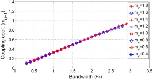
Fig. 2 presents an example of the optimized values of the coupling coefficients (mi,i+1) between two
adjacent resonators other than those at the junction. Those coupling coefficients linearly change with
the bandwidth of the channels Bw and they are independent of the channel position mv and then (4) is
deduced.
8- The self-coupling coefficients of the resonators (except resonators at the junction: R1, R2, R3 and
Rx) are displayed in Fig. 3 and they are found to be independent of the bandwidth Bw and their values
are very close to the channel position mv where mii=mv is deduced.
9- The graphs of the coupling coefficients at the junction: m12, m23 and m33 are presented in Figures
4, 5, 6 respectively. Curves in Fig. 4 represent quadratic equations for m12-mc versus channel
bandwidth where each curve is given for a certain channel position mv. It can be noticed that the
coupling coefficient m12 is dependent on channel bandwidth Bw, channel position mv and center
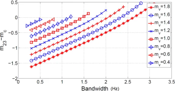
frequency mc. Moreover, the curves representing m23-mc in Fig. 5 vary linearly with bandwidth and
they are dependent on channel position mv. Furthermore, the coefficient m33 is depicted in Fig. 6 that
exhibits quadratic equations for m33-mv+mc versus channel bandwidth Bw. It is evident from Fig. 6 that
m33 depends on Bw, mv and mc.
10- The equations of the coupling coefficients at the junction (m12, m23 and m33) are empirically
deduced from the graphs in terms of the channel bandwidth Bw and channel position mv.
11- The coefficients of the linear/quadratic equations which are labeled (a, b, c) in equations (2, 3,
and 5) are also determined.
12- For diplexers with different number of resonators, the previous steps are repeated. Very similar
results for coupling coefficients have been obtained for diplexers with different number of resonators
Fig. 2. Optimized values of coupling coefficient mi,i+ 1.
Fig. 3. Optimized values of coupling coefficient mii.
Fig. 5. Optimized values of coupling coefficient m23.
Fig. 6. Optimized values of coupling coefficient m33.
III. NUMERICAL EXAMPLES
This section presents numerical examples for coupled resonator diplexers synthesized using
proposed equations in previous section. Five examples are given to prove the ability of the direct
method to satisfy various diplexers' characteristics and requirements. These examples are different in
number of resonators as well as different bandwidths. One of the examples is synthesized using direct
method and compared with a diplexer in a literature synthesized using optimization and implemented
using waveguide cavities.
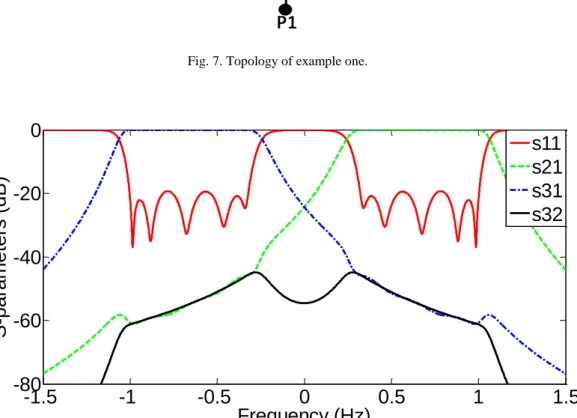
Fig. 7 presents the topology of example one which consists of ten resonators. The normalized edges
of the channels are x1=0.3, x2=1 and the normalized calculated coupling coefficients are m12=0.8127,
m23=m27=0.3659, m34=m78=0.2226, m45=m89=0.2226 and m56=m9,10=0.3032. The self-coupling
external quality factor of port two and port three is qe2=qe3=2.7754, while the normalized external
quality factor of the common port is qe1=1.3877. The diplexer response is presented in Fig. 8 and it
can be seen that the desired diplexer specification is achieved with five reflection zeros for each
channel and with the specified channel edges and return loss.
Fig. 7. Topology of example one.
-1.5
-1
-0.5
0
0.5
1
1.5
-80
-60
-40
-20
0
Frequency (Hz)
S
-p
a
ra
m
e
te
rs
(d
B
)
s11
s21
s31
s32
Fig. 8. Theoretical response of example one.
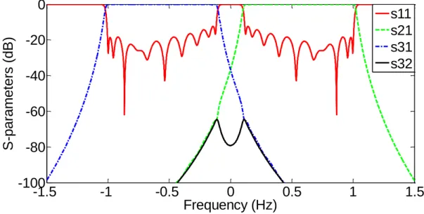
Topology in Fig. 9 presents the diplexer of example two of sixteen resonators. The normalized
edges of the channels are x1=0.15, x2=1 and the normalized coupling coefficients are m12=0.8218,
m23=m2,10=0.3838, m34=m10,11=0.2515, m45=m11,12=0.2354, m56=m12,13=0.2321, m67=m13,14=0.2354,
m78=m14,15=0.2515 and m89=m15,16=0.3498. The self-coupling coefficients are m11=m22=0, m33=˗ m10,10=
0.5178, m44=m55=m66=m77=m88=m99= ˗m11,11= ˗m12,12 = ˗m13,13= ˗m14,14= ˗m15,15 = ˗m16,16 =0.5750. The
normalized external quality factor of port two and port three is qe2=qe3=2.3932, while the normalized
external quality factor of the common port is qe1=1.1966. The response of the diplexer is shown in
Fig. 10 and it can be noticed that eight reflection zeros appear in each channel and that the specified
channel bandwidth is satisfied.
Example three is a diplexer formed of twenty coupled resonators and its topology is depicted in Fig.
factors are qe2=qe3=2.3364 and qe1=1.1682. The calculated normalized coupling coefficients are
m12=0.8226, m23=m2,12=0.3787, m34=m12,13=0.2570, m45=m13,14=0.2396, m56=m14,15=0.2342,
m67=m15,16=0.2328, m78=m16,17=0.2342, m89=m17,18=0.2396, m9,10=m18,19=0.2570, and
m10,11=m19,20=0.3580. The self-coupling coefficients are m11=m22=0, m33=˗m12,12=0.5109,
m44=m55=m66=m77=m88=m99=m10,10=m11,11=˗m13,13=˗m14,14=˗m15,15=˗m16,16=˗m17,17=˗m18,18=˗m19,19 =˗m20,20
= 0.5600. The diplexer response is presented in Fig. 12 and it is evident that the specification of the
diplexer is met which indicates that the proposed direct synthesis method is robust and convenient for
large topologies. If this diplexer is synthesized using optimization techniques, it requires more than
twenty variables with some constraints which may complicate the optimization problem and make the
solution infeasible.
Fig. 9. Topology of example two.
-1.5
-1
-0.5
0
0.5
1
1.5
-100
-80
-60
-40
-20
0
Frequency (Hz)
S
-p
a
ra
m
e
te
rs
(d
B
)
s11
s21
s31
s32
Fig. 10. Theoretical response of example two.
-1.5
-1
-0.5
0
0.5
1
1.5
-100
-80
-60
-40
-20
0
Frequency (Hz)
S
-p
a
ra
m
e
te
rs
(d
B
)
s11
s21
s31
s32
Fig. 12. Theoretical response of example three.
Example four presents a diplexer with twelve coupled resonators and its topology is shown in Fig.
13. The specifications of this diplexer are the same as those in [9] that is practically implemented
using waveguide cavity resonators at 10 GHz. The values of the boundaries are x1=0.30618 and x2=1
and the calculated normalized external quality factors are qe2=qe3=2.9806 and qe1=1.4903. A
comparison between coupling coefficients for both methods is shown in Table I that clearly shows
very close results for both methods. The response of diplexer four is depicted in Fig. 14 for both the
direct and optimization techniques. It can be seen from the graph that the plots of S-parameters are
close for both the proposed direct method and the optimization-based synthesis approach. The
optimization has been performed on computer with Intel processor core i7, a CPU at 2.4 GHz and a
RAM of 8 GB.
Fig. 13. Topology of example four.
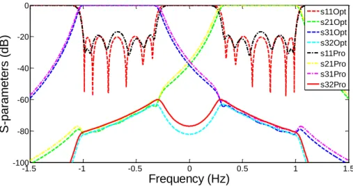
Example five presents a diplexer with fourteen coupled resonators and its topology is shown in Fig.
15. The values of the boundaries are x1=0.2 and x2=1 and the calculated normalized external quality
factors are qe2=qe3=2.52 and qe1=1.26. The coupling coefficients synthesized by both direct and
optimization methods are compared in Table II where it can be noticed that the results are close. Fig.
-1.5 -1 -0.5 0 0.5 1 1.5 -100
-80 -60 -40 -20 0
Frequency (Hz)
S
-p
a
ra
m
e
te
rs
(d
B
)
s11Opt s21Opt s31Opt s32Opt s11Pro s21Pro s31Pro s32Pro
Fig. 14. Theoretical response of example four.
TABLE I. NORMALIZED COUPLING COEFFICIENTS OF EXAMPLE FOUR
Norm. Coupling Coef. Proposed Method Optimization Method
m12 0.8125 0.7963
m23=m28 0.3560 0.3466
m34=m89 0.2039 0.2101
m45=m9,10 0.1946 0.195
m56=m10,11 0.2039 0.2035
m67=m11,12 0.2814 0.2814
m11=m22 0 0
m33=˗m88 0.6043 0.5942
m44=˗m99 0.6665 0.655
m55=˗m10,10 0.6665 0.6635
m66=˗m11,11 0.6665 0.6652
m77=˗m12,12 0.6665 0.6643
Time consumption Instant calculations 47.0782 second optimization time + time of writing
optimization code.
Complexity -No complexity, direct calculations from equations
-Complex cost function [see
equation (3) in [9].
-Large number of
optimization variables (17
variables).
The results of those previous examples verify that the proposed numerical equations achieve the
desired characteristics for different number of resonators and different channel bandwidths for
coupled resonator diplexer with T-topology. Moreover, the proposed method is preferred to
optimization techniques presented in literature for the given T-topology since the coupling
Fig. 15. Topology of example five.
-1.5 -1 -0.5 0 0.5 1 1.5
-100 -80 -60 -40 -20 0
Frequency (Hz)
S
-p
a
ra
m
e
te
rs
(d
B
)
s11Opt s21Opt s31Opt s32Opt s11Pro s21Pro s31Pro s32Pro
Fig. 16. Theoretical response of example five.
TABLE II. NORMALIZED COUPLING COEFFICIENTS OF EXAMPLE FIVE
Norm. Coupling Coef. Proposed Method Optimization Method
m12 0.8183 0.7790
m23=m29 0.3842 0.3646
m34=m9,10 0.2396 0.2304
m45=m10,11 0.2255 0.2165
m56=m11,12 0.2255 0.2146
m67=m12,13 0.2396 0.2242
m78=m13,14 0.3324 0.3162
m11=m22 0 0
m33=˗m99 0.5360 0.5188
m44=˗m10,10 0.6000 0.5877
m55=˗m11,11 0.6000 0.6022
m66=˗m12,12 0.6000 0.5953
m77=˗m13,13 0.6000 0.5928
m88=˗m14,14 0.6000 0.5950
Time consumption Instant calculations 328.5 second optimization time + time of writing
optimization code
Complexity -No complexity, direct calculations from equations
-Complex cost function [see
equation (3) in [9].
-Large number of
optimization variables (20
IV. CONCLUSION
This paper presents a novel direct approach for synthesis of coupled resonator diplexers with
T-topology. The proposed method is based on synthesis of coupling coefficients directly from equations
instead of optimization. The direct method achieves the desired diplexer characteristics for different
number of resonators and various bandwidth requirements. An illustration on deducing the proposed
equations from comprehensive optimization results is presented to give a good insight about the basis
of the method. Five examples are given to prove the validity of the approach for relatively large
number of resonators. Moreover, one numerical example is presented and compared to a diplexer
synthesized and implemented in previous literature. The proposed method beats the optimization
technique in reducing time consumption and complexity for structures with high number of
resonators.
REFERENCES
[1] J. Hong, M. Lancaster, Microstrip Filters for RF/Microwave Applications, Wiley Interscience Publication, New York, 2001. [2] D. Pozar, Microwave Engineering, 4th edition, Wiley, 2012.
[3] S. Amari, "Synthesis of cross-coupled resonator filters using an analytical gradient-based optimization technique," IEEE Trans. Microw. Theory Tech, vol. 48, no. 9, pp. 1559-1564, 2000.
[4] A. Atia, A. Zaki, E. Atia, "Synthesis of general topology multiple coupled resonator filters by optimization," in Proc. of IEEE MTT-S Int. Microwave Symposium, Baltimore, USA, 1998, pp. 821-824.
[5] B. Jayyousi, M. Lancaster, "A gradient-based optimization technique employing determinants for the synthesis of microwave coupled filters," in Proc. of IEEE MTT-S Inter. Microwave Symposium, USA, June 2004, pp. 1369-1372.
[6] M. Lancaster, “Radio frequency filter”, W.I.P.O patent WO/01/69712, 2001.
[7] T. Skaik, M. Lancaster, F. Huang, "Synthesis of multiple output coupled resonator microwave circuits using coupling matrix optimization," IET Journal of Microwaves, Antenna and Propagation, vol. 5, no. 9, pp. 1081-1088, June 2011.
[8] T. Skaik, T., M. AbuHussain, "Design of diplexers for E-band communication systems," in Proc. of the 13th Mediterranean Microwave Symposium, Lebanon, Sept. 2013.
[9] T. Skaik, M. Lancaster, "Coupled resonator diplexer without external junction," Journal of Electromagnetic Analysis and Applications, vol. 3, no. 6, pp. 238-241, June 2011.
[10] T. Skaik, M. Lancaster, M. Ke, Y. Wang, "A micro-machined WR-3 waveguide diplexer based on coupled resonator structures," in Proc. of the 41st European Microwave Conference, UK, Oct 2011, pp. 770-773.
[11] W. Xia, X. Shang, M. Lancaster, "All-resonator-based waveguide diplexer with cross-couplings," in Electronics Letters, vol. 50, No. 25, pp. 1948-1950, 2014.
[12] F. Loras-Gonzalez, I. Hidalgo-Carpintero, S. Sobrino-Arias, A. Garca-Lamprez, M. Salazar-Palma, "A novel Ku-Band dielectric resonator triplexer based on generalized multiplexer theory," in Proc. of IEEE MTT-S International Microwave Symposium, 2010, Anaheim, CA, 2010, pp. 884-887.
[13] T. Skaik, "Novel star junction coupled resonator multiplexer structures," Progress in Electromagnetics Research Letters, vol. 31, pp. 113-120, April 2012.
[14] D. Tubail, T. Skaik, "Synthesis of coupled resonator based multiplexers with generalized structures using coupling matrix optimization," IET Electronic Letters, vol. 51, no. 23, pp. 1891-1893, Nov 2015.
[15] A. Garcia-Lamperez, M. Salazar-Palma, T. Sarkar, "Compact multiplexer formed by coupled resonators with distributed coupling," in Proc. IEEE Antennas and Propagation Society International Symposium, USA, 2005, pp. 89-92.
[16] T. Skaik, D. Tubail, "Novel multiplexer topologies based on coupled resonator structures," in Proc. of the 15th Mediterranean Microwave Symposium, Lecce, Italy, Dec. 2015.
[17] X. Shang, Y. Wang, X. Wenlin, M. Lancaster, "Novel multiplexer topologies based on all-resonator structures," IEEE Transactions Microwave Theory and Techniques, vol. 61, no. 11, pp. 3838-3845, 2013.
![Fig. 1 exhibits the main coupled resonator diplexer topology presented in [7]-[10], where the coupling between the resonators, self-coupling and the external coupling coefficients are obtained using coupling matrix optimization](https://thumb-eu.123doks.com/thumbv2/123dok_br/18888251.424351/2.892.134.775.374.576/exhibits-resonator-diplexer-topology-presented-resonators-coefficients-optimization.webp)