Brazilian Microwave and Optoelectronics Society-SBMO received 15 June 2017; for review 26 June 2017; accepted 27 Sep 2017 Brazilian Society of Electromagnetism-SBMag © 2017 SBMO/SBMag ISSN 2179-1074
Abstract— A novel design of a printed bowtie antenna without a ground plane and with size below a quarter wavelength for RFID readers is presented. Due to the lack of a ground plane, the designed antenna has omnidirectional characteristics and is insensitive to small permittivity deviations. For matching purposes without introducing gain distortion, a shorting strip connecting the radiating arms and four triangular shaped extensions of the radiating arms are added to the antenna design. Measurements show that operation in the 915 MHz band is met with a bandwidth of 13% (S11 < -10 dB) and gain around 2 dBi, while presenting an omnidirectional radiation pattern. Also, the proposed antenna design can be easily modified to operate at neighboring frequency bands.
Index Terms—Printed antennas, UHF, shorting strip, bowtie, RFID. I.INTRODUCTION
Radio frequency identification (RFID) systems are adequate for real-time tracking and management
of objects and people. Its application ranges from industry production to healthcare systems. Recent
trends in logistics and supply chain management require fixed RFID readers with reduced size
antennas. Also, in some situations an omnidirectional radiation is desired for this class of readers. The
challenge of impedance matching in limited size RFID reader antennas is dealt with several design
techniques: replacing radiating elements with artificial transmission lines [1], adopting a
microstrip-to-coplanar stripline Marchand balun [2], introducing four tuning stubs and an L-shaped metal strip in
a slot antenna [3], with a multi-objective optimization approach [4]. Other size reduction techniques
are described in [5-7].
Alternative antenna designs that ensures low-cost, reduced size, simple geometry, robustness
against manufacturing errors and presents an omnidirectional radiation pattern are desired. A suitable
approach for this purpose would be a printed bowtie like antenna, since simple improvements can be
made for setting up its operating frequency. Indeed, the antenna design proposed in this article is a
printed bowtie antenna that complies with its specified size restriction as a consequence of the
Optimized Limited Size Printed Bowtie
Antenna for UHF RFID Readers
Leandro Andrade-Fonseca,
Department of Communications, School of Electrical and Computer Engineering, State University of Campinas, Campinas, São Paulo, Brazil, [email protected]
Adriano C. Lisboa,
Gaia Solutions on Demand, Belo Horizonte, Minas Gerais, Brazil, [email protected] Ricardo Adriano and Elson J. Silva
Brazilian Microwave and Optoelectronics Society-SBMO received 15 June 2017; for review 26 June 2017; accepted 27 Sep 2017 Brazilian Society of Electromagnetism-SBMag © 2017 SBMO/SBMag ISSN 2179-1074 introduced modifications.
This article presents a novel design of a modified printed bowtie antenna fed by a 50 Ω coaxial line for fixed RFID readers operating from 902 MHz to 928 MHz. In the literature, printed bowtie
antennas are sometimes mounted above a ground plane [8-9]. However, in order to preserve the
omnidirectional radiation pattern, which is necessary for some RFID fixed reader applications, the
ground plane is discarded in our design. Without a conventional ground plane, the antenna is not
sensible to small permittivity deviations and an omnidirectional gain is obtained. As to overcome
limitations imposed by coaxial feeding, impedance tuning is attained by adding a shorting strip
between its radiating arms and four triangular shaped extensions of the radiating arms. The added
modifications does not distort the radiation pattern of the antenna, so that the gain of a regular printed
bowtie antenna is preserved. Moreover, the operating band of the antenna can easily be shifted by
adjusting the parameters of both the shorting strips and the radiating arms extensions, so that specific
UHF RFID frequency bands are managed with few adjustments. Maximum dimensions for this
antenna are 0.23λ × 0.23 λ × 0.005λ , where λ is the vacuum wavelength of the center frequency at
915 MHz. Measurements shows operation with S11 < -10 dB in the 915 MHz band with a bandwidth
of 13% (858-982 MHz) and gain around 2 dBi, while presenting an omnidirectional radiation pattern.
A. Antenna design workflow
In this work, at first a classical printed bowtie antenna fed by a coaxial line is modeled and
optimized. However, as the largest size of the substrate is less than a quarter of the operating
wavelength, the desired specifications cannot be achieved. Then, by introducing and adjusting
modifications on the geometry of the antenna, considerable low values of VSWR at the operating
frequency are obtained, and an omnidirectional gain is accomplished. Introduced modifications does
not distort radiation pattern of the antenna, so that the gain of a regular printed bowtie antenna is
preserved. Overall, the work-flow of the antenna design is:
i. Design a classical printed bowtie antenna without a conventional ground plane.
ii. Optimize the classical bowtie antenna.
iii. Introduce a first modification to the classical bowtie antenna: a shorting strip between its
radiating arms.
iv. Introduce a second modification to the classical bowtie antenna: four triangular shaped
extensions of the radiating arms.
v. Adjust the parameters of the two introduced modification to improve the antenna performance
and handle its specifications.
All computational models were built with Ansys HFSS software [10]. The interface between the
Brazilian Microwave and Optoelectronics Society-SBMO received 15 June 2017; for review 26 June 2017; accepted 27 Sep 2017 Brazilian Society of Electromagnetism-SBMag © 2017 SBMO/SBMag ISSN 2179-1074
II. CLASSICAL BOWTIE DESIGN
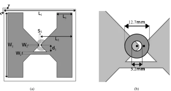
Initially a classical printed bowtie antenna is designed, as shown in Fig. 1, without a ground plane.
Parameterization is also presented in this figure. Note that the conductive part shown in Fig. 1(b) is
just an extension of the outer conductor of the coaxial line, used only for feeding purposes. This
coaxial line transition acts as a balanced to unbalanced balun impedance matching transformer.
(a) (b)
Fig. 1. Classical bowtie design. The white inside the L1 sided box depicts the FR4 substrate, gray depicts conducting parts,
black circles depicts via holes for feeding. a) Top View. b) Bottom view.
The antenna is printed on a FR-4 substrate with dimensions L1 × L1 × h, where h is the substrate thickness, with a dielectric constant r =4.4 and loss tangent tan = 0.02. The dielectric is used for mounting purposes and does not affect the antenna operation considerably. With a 1.6 mm substrate
height and a neglected ground plane, the dielectric losses due to the low-cost lossy dielectric adopted
are avoided, therefore a high radiation efficiency is ensured. In RFID readers the maximum
dimensions for the antenna is a major constraint in the antenna design. Usually less than a quarter of a
wavelength is available in the RFID system for the antenna. Here the substrate dimensions are fixed at
75 × 75 × 1.6 mm³ in order to comply with specifications of a fixed RFID reader device under
development.
A. Antenna feeding
Although microstrip transmission lines are widely used for feeding printed antennas, microstrip
feeding method requires considerable increase in ground plane, which would distort the desired
omnidirectional radiation pattern. Recent antenna designs [11, 12] inserts defects in the ground plane
for size reduction and to excite additional resonance bands. But, these defects are not applicable in the
present design.
For the proposed antenna design, a coaxial transition feeding method was chosen in order to
achieve a simple and low-cost design. Furthermore, with this feeding method the ground plane can be
Brazilian Microwave and Optoelectronics Society-SBMO received 15 June 2017; for review 26 June 2017; accepted 27 Sep 2017 Brazilian Society of Electromagnetism-SBMag © 2017 SBMO/SBMag ISSN 2179-1074
B. Classical bowtie optimization
The antenna parameters [L2, W1, W2, S1] are subjected to an optimization problem for maximum
VSWR minimization from 900 MHz to 930 MHz. The Differential evolution (DE) algorithm [13] is
applied. The optimization problem objective function is the maximum antenna VSWR value in the
900-930 MHz frequency range [4]. With this objective function the best parameters settings can be
achieved for operation at the desired frequency range.
After several iterations of the optimization, the best individual achieved maximum VSWR of 6.9 at
the operating frequency, which is highly undesired. High VSWR values are caused mainly due to
substrate side size restriction. The optimal parameters are L2=35.3 mm, W1=1.2 mm, W2=73 mm,
S1=2 mm. The distance from the central point of the antenna to the feeding point, represented as black
circles in Fig. 1, is 1.2 mm. Fig. 2 presents return loss simulation in a blue color dashed line, which
shows an impedance matching around 1,150 MHz.
Fig. 2. Comparative simulations of return loss for printed bowtie antennas over a large bandwidth.
It is clear that impedance matching techniques must be applied in order to obtain reasonable values
of VSWR at the operating frequency range. Since a feed reshaping is not feasible, the above
mentioned matching techniques are not applicable. Therefore, antenna characteristics were improved
as described in the following sections, while the antenna bottom face is kept the same as the one
shown in Fig. 1(b).
III. PROPOSED MODIFICATIONS
For a proper impedance matching, a shorting strip between the radiating arms and four triangular
shaped extensions of the radiating arms are added to the classical bowtie antenna presented in section
II, thus reshaping it. The proposed modified bowtie antenna design is depicted in Fig. 3, where the
Brazilian Microwave and Optoelectronics Society-SBMO received 15 June 2017; for review 26 June 2017; accepted 27 Sep 2017 Brazilian Society of Electromagnetism-SBMag © 2017 SBMO/SBMag ISSN 2179-1074
(a) (b)
Fig. 3. Proposed antenna design and main parameters. (a) Top view with shorting strip and radiating arms extensions. (b) Bottom view.
A. Shorting Strip
Close to the gap at the feeding region, a shorting strip is inserted connecting both bowtie radiating
arms as shown in Fig. 3. The shorting strip is parameterized by two variables: its distance d1 from the
center of the antenna, and its track width W3. By adjusting these parameters, the input impedance Zin
of the antenna can be significantly changed. For example, the capacitive coupling generated by the
gap that separates both radiating arms of the antenna can be compensated with the shorting strip. The shorting strip effect on the antenna’s input impedance is shown in Fig. 4, in which the capacitive coupling is compensated in almost half of its bandwidth. In this figure the Zin of the
classical bow-tie antenna with and without the shorting strip can be compared. In the proposed
antenna the shorting strip increases the Re(Zin) and the undesired gap capacitive coupling was reduced
in a significant portion of the frequency band.
(a) (b)
Brazilian Microwave and Optoelectronics Society-SBMO received 15 June 2017; for review 26 June 2017; accepted 27 Sep 2017 Brazilian Society of Electromagnetism-SBMag © 2017 SBMO/SBMag ISSN 2179-1074 The shorting strip parameters are subjected to a local adjustment for minimizing VSWR, and then
are set as d1=2.9 mm and W3=0.3 mm. Simulation of the return loss for the printed bowtie antenna
with shorting strip is presented with the color black in Fig. 2. Only by adding this connection,
maximum VSWR values decrease from 6.9 to 2.8 at the operating frequency. Furthermore, return loss
is shifted towards the desired operating frequency, as shown in the same figure.
Indeed, an improvement was observed with the advent of the shorting strip. However, it is clear that
in order to achieve a perfect matching, the return loss must be further shifted towards the operating
frequency. Such improvement can be attained by decreasing the Re(Zin).
B. Shorting strips and radiating arms extensions
Aiming to improve the bandwidth of its designed antenna, [2] uses a closely-coupled parasitic
element. Differently, [14] reports shorted parasitic elements for bandwidth improvement. Inspired by
these, in the present design four triangular shaped elements are inserted close to the outermost vertex
of the bowtie antenna, extending its radiating arms.
It was observed through simulation that, in this case, connecting the triangular shaped elements
with the radiating arms performs a better impedance matching than detached elements. Additionally,
the design complexity is not affected with the new elements directly connected to the radiating arms,
only one new degree of freedom is inserted. The radiating arms extensions are parameterized with one
parameter only, which is L3, as shown in Fig. 3.
Pursuing to shift the return loss to the desired operating frequency, the L3 parameter is also
subjected to a local adjustment for VSWR minimization in the operating frequency bandwidth, which
results in L3=16.3 mm.
Simulation of the proposed antenna with both radiating arms extensions and shorting strip is also
depicted in Fig. 2 in the red color solid line, with the optimal parameter set. The return loss placement
suggests that a proper matching is obtained for the proposed antenna at the desired operating band of
915 MHz. The maximum VSWR value at the 902-928 MHz bandwidth is 1.32, which implies an
almost perfect match with the 50 Ω coaxial line. This impedance matching is achieved since the
Re(Zin) is shifted to almost 50 Ω through the operating frequency bandwidth due to the radiating arms
extensions. Therefore, the shorting strip along with the triangular shaped extensions of the radiating
arms are a simple and efficient tool for impedance matching.
C. Final antenna design
So, in the final antenna design the parameters [d1, L3, W3] are adjusted as to attain a perfect
impedance matching with the fed line. This is done by experimental test, which is suitable because of
few parameters. Finally, the proposed modified bowtie antenna design optimal dimensions are: L1=75
mm, L2=35.3 mm, W1=1.2 mm, W2=73 mm, W3=0.3 mm, S1=2 mm, d1=2.9 mm and L3=16.3 mm.
D. Dealing with FR-4 εr deviation
Brazilian Microwave and Optoelectronics Society-SBMO received 15 June 2017; for review 26 June 2017; accepted 27 Sep 2017 Brazilian Society of Electromagnetism-SBMag © 2017 SBMO/SBMag ISSN 2179-1074 depending on its manufacturer. An antenna with r insensitiveness is desired when a low-cost dielectric is used. However, in this antenna design the substrate is adopted for mounting purpose only, the antenna resonance is not considerably affected by r deviation. The proposed optimized and modified antenna was simulated thrice with r =4.2, r =4.4 and r =4.6, the results are presented in Fig. 5. This figure shows that there is no significant variation for VSWR values through the operating
frequency bandwidth.
Fig. 5. Simulated VSWR of the proposed antenna when the FR-4 r is varied.
IV. EASINESS OF FREQUENCY SHIFTING
The UHF RFID frequency band is country dependent, therefore, reader antennas must be easily
scalable for specific frequency bands. Some examples of UHF RFID frequency assignments are:
Europe (866-869 MHz), North and South America (902-928 MHz) and Japan (950-956 MHz). The
operating frequency of the antenna design presented in this paper can be easily shifted by simply
adjusting the parameters of both the shorting strip and the triangular shaped extensions, which is a
relevant advantage compared to other designs.
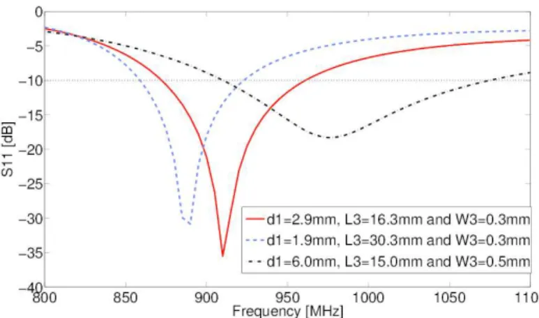
Fig. 6 presents some alternative parameters settings for [d1, L3, W3] obtained from simulation. It can
be seen that the added modifications can be used to shift the operating band of the antenna for other
frequency ranges. Only by setting d1=1.9 mm, L3=30.3 mm and W3=0.3 mm operation at lower
frequencies ranges can be achieved. On the other hand, setting d1=6 mm, L3=15 mm and W3=0.5 mm
allow the designed antenna to operate in higher frequency bands.
Brazilian Microwave and Optoelectronics Society-SBMO received 15 June 2017; for review 26 June 2017; accepted 27 Sep 2017 Brazilian Society of Electromagnetism-SBMag © 2017 SBMO/SBMag ISSN 2179-1074 The Table I. below details the simulated bandwidth for the three above mentioned UHF RFID
frequency bands. In higher frequencies the impedance matching is broadened since the antenna is
electrically larger.
Table I. Designed antenna frequency shift
Frequency Band Bandwidth (%)
867.5 MHz 9.29
915 MHz 6.92
953 MHz 16.26
V. MEASURED RESULTS
In order to fully characterize and verify the designed antenna with its final optimal dimensions,
return loss and gain measurements were conducted. The fabricated antenna is shown in Fig. 7.
(a) (b)
Fig. 7. Photograph of the fabricated antenna, where the light green region depicts the conductive parts. The shorting strip is the thin line between the radiating arms. (a) Top view, (b) bottom view.
Fig. 8 shows a good agreement between return loss simulation (S11) and measurement. The
simulated bandwidth with S11 < -10 dB is 9.29% (875-960 MHz), while the measured bandwidth is
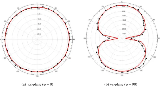
13.55% (858-952 MHz). Fig. 9 presents gain radiation pattern simulation and measurement, which
confirms the expected antenna performance. Approximately 2 dBi peak gain was observed in
measurement, which is in compliance with the simulated one. Omnidirectional gain is observed at the
Brazilian Microwave and Optoelectronics Society-SBMO received 15 June 2017; for review 26 June 2017; accepted 27 Sep 2017 Brazilian Society of Electromagnetism-SBMag © 2017 SBMO/SBMag ISSN 2179-1074
Fig. 8. Return loss simulation and measurement.
(a) xz-plane (φ = 0) (b) yz-plane (φ = 90)
Fig. 9. Simulated and measured radiation patterns for the proposed modified bowtie antenna. The simulation is in color red with a line, and the measurement is in color black with lines and point markers.
VI. CONCLUSION
A novel design of a printed bowtie antenna is proposed, in which the conventional ground plane
that occupies one face of the substrate is removed. Therefore, an omnidirectional gain is achieved. The antenna design is not sensitive to r since the substrate is used mainly for mounting purposes. The proposed combined alterations of shorting strip and radiating arms extensions for impedance
matching improved the antenna as desired, without changing its size and feeding method. Another
advantage of the antenna design presented is that by simply adjusting parameters of the added
modifications, operation at specific RFID bands and other frequency bands can be achieved. Also,
gain characteristics of the respective regular printed bowtie antenna were preserved. Furthermore, the
novel proposed combined method for matching does not increase design complexity. Therefore
Brazilian Microwave and Optoelectronics Society-SBMO received 15 June 2017; for review 26 June 2017; accepted 27 Sep 2017 Brazilian Society of Electromagnetism-SBMag © 2017 SBMO/SBMag ISSN 2179-1074
ACKNOWLEDGMENT
This work was supported by CNPq, CAPES and FAPEMIG, Brazil.
REFERENCES
[1] P. Hajizadeh, H. R. Hassani, S. H. Sedighy, Planar artificial transmission lines loading for miniturization of rfid printed quasi-yagi antenna, IEEE Antennas and Wireless Propagation Letters 12 (2013) 464–467.
[2] R.-C. Hua, T.-G. Ma, A printed dipole antenna for ultra high frequency (uhf) radio frequency identification (rfid) handheld reader, IEEE Trans. Antennas Propag. 55 (12) (2007) 3742–3745.
[3] B. Xu, S. Zhang, Y. Liu, J. Hu, S. He, Compact broadband circularly polarised slot antenna for universal uhf rfid readers, Electronics Letters 51 (11) (2015) 808–809.
[4] D. B. Oliveira, A. C. Lisboa, L. A. C. Fonseca, E. J. Silva, R. Adriano, Low-cost antenna design for rfid readers using multiobjective optimization, Microwave and Optical Technology Letters 58 (4) (2016) 905–908.
[5] H.-W. Liu, C.-F. Yang, C.-H. Ku, Novel miniature monopole tag antenna for uhf rfid applications, IEEE Antennas Wireless Propag. Lett. 9 (2010) 363–366.
[6] Z. L. Ma, L. J. Jiang, J. Xi, T. Ye, A single-layer compact hf-uhf dualband rfid tag antenna, IEEE Antennas Wireless Propag. Lett. 11 (2012) 1257–1260.
[7] W. Yeoh, K. Wong, W. Rowe, Wideband miniaturized half bowtie printed dipole antenna with integrated balun for wireless applications, IEEE Trans. Antennas Propag. 59 (1) (2011) 339–342.
[8] Bailey, M. Broad-band half-wave dipole. IEEE transactions on antennas and propagation 32.4 (1984): 410-412. [9] Wong, Hang, Ka-Ming Mak, and Kwai-Man Luk. Wideband shorted bowtie patch antenna with electric dipole. IEEE Transactions on Antennas and Propagation 56.7 (2008): 2098-2101.
[10] Ansys HFSS simulator version 13.
[11] A. K. Gautam, A. Bisht, B. K. Kanaujia, A wideband antenna withdefected ground plane for wlan/wimax applications, (AEU) - International Journal of Electronics and Communications 70 (3) (2016) 354 - 358.
[12] M. K. Khandelwal, B. K. Kanaujia, S. Dwari, S. Kumar, A. Gautam, Analysis and design of dual band compact stacked microstrip patch antenna with defected ground structure for wlan/wimax applications, {AEU} - International Journal of Electronics and Communications 69 (1) (2015) 39 – 47.
[13] R. Storn, K. Price, Differential evolution – a simple and efficient heuristic for global optimization over continuous spaces, J. of Global Optim. 11 (4) (1997) 341–359.