Objective: To assess whether palatal mini-implants are effective as direct anchorage for distal movement of the up-per molars. Methods: It was used an acrylic model of the upper dental arch. After making a groove in the region corresponding to dental alveolus, acrylic teeth were fixed in groove with #7 wax, with the roots being previously immersed in adhesive wax. The orthodontic appliance was placed according to the Edgewise technique and then a mini-implant (SIN, São Paulo, Brazil) was inserted at the site corresponding to the palatal raphe. A 0.019 x 0.025-in stainless steel archwire was made and attached to the upper arch with elastics. A transpalatal arch bar (0.019 x 0.025-in) was mounted and two hooks were soldered to it in order to retain chain elastics (Unitek, Brazil) to be connected to the mini-implant under a force of 1.5 N on each side. The maxillary model was immersed in water 40 times and photographed after each immersion, for observation of dental movements. Analysis of variance (ANOVA) and Tukey’s test were employed for analyzing the obtained data. Results: Molars displaced distally 3.1 mm, in average, with distal inclination ranging from 3 to 5 mm. Conclusions: Molar movements occurred due to distal inclination, with a slight rotation and no extrusive effect.
Keywords: Tooth movement. Orthodontic anchorage procedures. Hard palate.
Distal movement of upper permanent
molars using midpalatal mini-implant
Ana de Lourdes Sá de Lira1, Sávio Prado2, Mônica Tirre Araújo3,
Eduardo Franzotti Sant’Anna3, Antonio Carlos de Oliveira Ruellas3
How to cite this article: Lira ALS, Prado S, Araújo MT, Sant’Anna EF, Ruellas ACO. Distal movement of upper permanent molars using midpalatal mini-implant. Dental Press J Orthod. 2013 Mar-Apr;18(2):18.e1-5.
Submitted: May 15, 2009 - Revised and accepted: April 12, 2010
Contact address:Ana de Lourdes Sá de Lira Rua Motorista Gregório, 2530 – Horto Florestal CEP: 64052-140 – Teresina/PI – Brazil E-mail: anadelourdessl@hotmail.com
1 Professor of the specialization courses in Orthodontics, UFPI.
2 Adjunct Professor, UFPA.
3 Adjunct Professor, UFRJ.
» The authors report no commercial, proprietary or financial interest in the products or companies described in this article.
Objetivo: verificar se o mini-implante no palato é eficaz como ancoragem direta para distalização dos molares superiores. Métodos: foi utilizado um modelo em acrílico da arcada superior. Após a confecção da canaleta na região correspondente aos alvéolos dentários, os dentes em acrílico foram fixados com cera #7, montado aparelho ortodôntico com a técnica Edgewise e inserido um mini-implante (SIN, São Paulo) no local correspondente à rafe palatina. Foram colocados arco 0,19” x 0,25” e barra transpalatina, soldados na barra dois ganchos para retenção de dois elásticos em cadeia de dois elos, a uma carga de 150g/f de cada lado (Unitek), que se estenderam dos ganchos até o mini-implante. O modelo da maxila foi mergulhado 40 vezes em banheira e fotografado após cada mergulho para observação da movimentação dentária. Os dados foram analisados pela análise da variânçia (ANOVA) e teste de Tukey. Resultados: os molares deslocaram-se distalmente 3,1mm, em média, com inclinação distal entre 3 e 5mm.
Conclusões: a movimentação dos molares ocorreu pela inclinação distal, com leve rotação, mas sem efeito extrusivo.
INTRODUCTION
Methods for controlling anchorage during distal movement of molar teeth tend to cause undesirable movements in other teeth, and they also depend on the patient’s cooperation when extraoral anchorage is use. However, with the advent of skeletal anchor-age, such a disadvantage has been overcome and gain
respect among orthodontists.17
The orthodontic use of palatal mini-implants for
anchorage was first described in the 90’s,22 and
addi-tional studies on skulls were carried out to determine
the most suitable area for placement of these devices.23
Palatal mini-implants can be used as skeletal an-chorage because the midpalatal suture has cortical bone enough to support them and, in addition, there are no tooth roots, nerves or blood vessels in this
region, which makes surgical procedures difficult.1
Similarly to other mini-implants, the palatal ones al-low immediate load application without suffering os-seointegration, thus being easily removed, as they are made of titanium-aluminium alloy instead of pure
titanium, as in the conventional implants.17
Palatal mini-implants can be used for direct or indirect anchorage. In the former case, force is di-rectly applied to the mini-implant, whereas in the latter case force is applied to a group of teeth in or-der to stabilise them. This is achieved by means of a transpalatal arch with adequate dimensions so that anchorage loss could be prevented due to the
intrin-sic elasticity of the system.23
Some authors suggest the placement of a mini-implant in the palatal midline, for molar distal move-ment and application of force by means of palatal bar, since the cortical bone has excellent quality. This eliminates the need to remove the mini-implant dur-ing retraction of anterior teeth as it occurs when the mini-implants are inserted buccally. However, load application for the movement described earlier is of difficult control, because the point of application of the force is above the center of resistance and pro-motes dental inclination, with distal movement being
more enhanced in the root portion.5,18
As the palatal suture is thick, the mini-implant for this region should have a diameter greater than that for the alveolar ridge, and in case of primary instability, the mini-implant should be inserted
ad-jacently to the suture.23
The objective of the present study was to assess whether palatal mini-implants provide effective an-chorage for distal movement of the upper molars un-der forces similar to the orthodontically applied ones.
MATERIAL AND METHODS
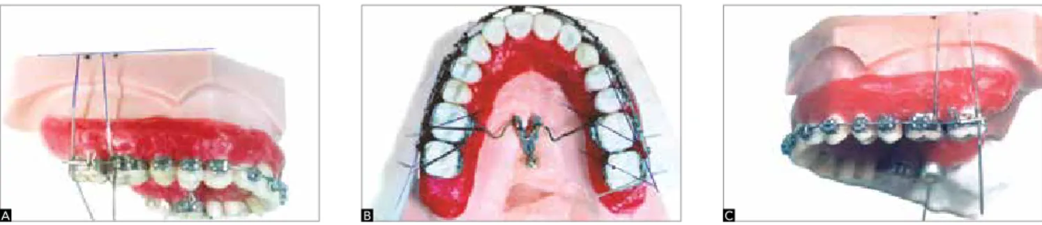
Five upper arch plaster models made in acrylic were used; with resin teeth; bands for permanent first and second molars; brackets for bonding on the other anterior teeth; a 0.019 x 0.025-in wire; a 0.9-mm wire; two double molar tubes; two first molars twin brackets for welding; two single molar tubes for sec-ond molars (Unitek, Rio de Janeiro, Brazil) and one mini-implant (SIN, São Paulo, Brazil).
A groove was made in the region corresponding to dental alveolus to be then filled with #7 wax. Acrylic teeth were fixed in the groove with this wax, with their roots being previously immersed in adhesive wax. The brackets, whose bonding sites were previously sand-blasted with aluminium oxide, were bonded from right second premolar to left second premolar with resin (Concise) according to the Edgewise technique. The mini-implant was inserted in the region corresponding to the palatal midline between the first molars by using an appropriate screw-drive. Orthodontic bands for the first and second molars were selected and the respective accessories were buccally welded to them as well as a 0.019 x 0.025-in rectangular 5-cm wire, perpendicular to its cervical third. A 0.019 x 0.025-in archwire was made and attached to the upper arch with elastics. Dou-ble tubes were welded on the lingual aspect of the first molar bands for adaptation of the transpalatal bar, and later the bands were bonded. The transpalatal bar was made of 0.9 x 0.9-mm wire and adapted to the tubes, with its curvature between the second premolars, be-ing welded in it two hooks for retention of double link chain elastics (Unitek), both reaching the mini-implant under a load of 150 gf each, totalizing a load of 300 gf.
The upper arch model was immersed in water at a
temperature of 60 oC until the wax softened and then
guarantee the reliability of the experiment. After each immersion, the shift of the permanent molars was recorded in the occlusal photographs and a digital calliper was used to measure the shortest distance be-tween the occlusal surface of the first molars and the second premolars. A line connecting the buccal cusps of the premolars at each side was traced in the occlu-sal photographs. Other two lines were also traced on the enamel bridges of the first and second permanent molars on both sides (Figs 1 and 2).
The inner angles formed by the intersection of these lines traced on the photographs, taken before and after immersion of the upper arch model, were measured. In addition, the shortest distance between second premolars and first molar at the interproximal space was measured as well. In the lateral photographs, the angle between the upper edge of the model and the wire welded buccally to the first and second mo-lars on each side was measured before and after each immersion, to verify any distal movement or inclina-tion of these teeth. The experiment was performed 40
Figure 2 - Final photographs: A) right side, B) occlusal view, C) left side. Figure 1 - Initial photographs: A) right side, B) occlusal view, C) left side.
A
A
B
B
C
C
times, with the wax being replaced after every 5 im-mersions. Two hundred and forty photographs were ob-tained for each model, being three before and three after each immersion, for each model. Thus, for the 5 studied cast models 1,200 photographs were evaluated, all taken and analyzed by the same observer. For each linear and angular measurement, the mean and standard deviation
was calculated at the time before the immersion (T0) and
after it (T1). The behavior of the measures between the
times (T1 x T0) was tested for significance with the paired
Student t test, with significance level of 5%.
Method error
One hundred and twenty photographs were ob-tained from two randomly chosen models, before be-ing subjected to immersion. No significant difference was found using the paired t test. The accuracy of the measurements was calculated using the Dahlberg’s
for-mula.6 For the angular measurements, the method
region is secure and allows easy access, with low sus-ceptibility of inflammation due to the existing fibrous connective tissue. In addition, palatal mini-implant does not interfere with dental movement, although this may occur if mini-implants are placed onto alve-olar processes. Nevertheless, the length of the mini-implant should not exceed 4-6 mm in order to avoid
the risk of perforation of the nasal cavity.22
Intraoral appliances and devices have been intro-duced to minimize the need for patient cooperation, which is required with the use of extraoral
applianc-es.16 Among them, one can cite the following:
Repel-ling magnet,7 arches with coil springs,9,10 NiTi
super-elastic arches,19 Jones jig,10,13 distal jet,4,21 Keles
Slid-er,15 pendulum appliance2,7,13 and K-loop.3 Although
these appliances are aimed at applying a continuous distal force to molars, they also promote mesial force on anterior teeth. Therefore, loss of anchorage result-ing in protrusion of anterior teeth also occurs. Distal inclination and extrusion of upper first molars have been observed and considered as undesirable move-ments during distal movement using these intraoral
appliances.2,3,4,6,9-15,20,21 The mechanics involving
in-traoral Class II elastics also have harmful effects, such as extrusion of lower molars, retroclination of upper
incisors and projection of lower incisors.12
With the advent of mini-implants, however, the anchorage problem of anterior teeth during distal movement of molars has been solved. However, dis-RESULTS
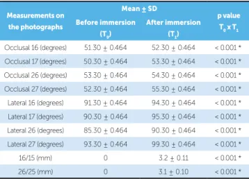
In the analysis of occlusal photographs of the upper arch, it was observed a mean distal rotation of 1 degree in the first permanent molars and 3 degrees in the sec-ond permanent molars. Observing the buccal aspect of the intraoral lateral photographs, the crowns of the first permanent molars on the right and left sides were found to be distally inclined, in average, 3 degrees and 5 degrees, respectively. On the other hand, the second permanent molars inclined distally, in average, 5 de-grees on both sides (Table 1).
As regards the linear measurements performed on 400 occlusal photographs of the five plaster models, it was observed that molars crowns shifted 3.2 mm dis-tally, in average, on the right side, and 3.1 mm on the left side, presenting statistical significancy (Table 1).
DISCUSSION
The results have shown that palatal mini-implant is ef-ficient as a direct anchorage device for distal movement of molars, although distal rotations of 3 degrees and 1 degree had occurred, respectively, in second and first molars. As the transpalatal bar was mounted and attached to first molars by means of ligature wires, a smaller moment of distal inclination was generated onto these teeth, com-pared to second molars. This is due to the fact that distal forces generate a moment of distal inclination, while the bar movement inside the lingual tube of the first mo-lars generates moment of mesial inclination. The second molars had a greater distal inclination because during distal movement they received only distal forces without suffering the effect of mesial moment, as they did not have a bar associated.
No molar extrusion was observed, probably due to the force being applied above the centre of resistance and parallel to the occlusal plane. Distal molars dis-placement of 3.1 mm, in average, with mesial diaste-mas in the second premolars was found. This suggests that distal movement of the first and second molars can be simultaneously achieved by means of skeletal anchorage in the palatal raphe. Similar results were
re-ported by Lim an Hong,19 although differing in terms
of neutralization of rotation and distal inclination of the molars as skeletal anchorage involved the palatal raphe and alveolar border buccally.
Because palatal raphe is composed of a thick cor-tical bone, the placement of a mini-implant in this
Table 1 - Mean values of angular measurements regarding upper first and second permanent molars assessed on occlusal and lateral photographs of the right and left sides.
16, 17, 26 and 27 = first and second molars on the right and left sides, respec-tively. * p = 5% significance.
Measurements on
the photographs
Mean ± SD
p value
T0 x T1 Before immersion
(T0)
After immersion
(T1)
1. Block MS, Hoffman DR. A new device for absolute anchorage for orthodontics. Am J Orthod Dentofacial Orthop. 1995;107(3):251-8.
2. Byloff FK, Darendeliler MA. Distal molar movement using the pendulum
appliance. Part 1: clinical and radiological evaluation. Angle Orthod. 1997;67(4):249-60.
3. Byloff FK, Kärcher H, Clar E, Stoff F. An implant to eliminate anchorage loss during molar distalization: a case report involving the Graz implant-supported pendulum. Int J Adult Orthodon Orthognath Surg. 2000;15(2):129-37.
4. Carano A, Testa M. The distal jet for upper molar distalization. J Clin Orthod. 1996;30(7):374-80.
5. Crismani AG, Celar AG, Burstone CJ, Bernhart TG, Bantleon HP,
Mittlboeck M. Sagittal and vertical load-deflection and permanent deformation of transpalatal arches connected with palatal implants: an in-vitro study. Am J Orthod Dentofacial Orthop. 2007;131(6):742-52. 6. Dahlberg G. Statistical methods for medical and biological students.
London: Allen & Unwin; 1940.
7. Ghosh J, Nanda RS. Evaluation of an intraoral maxillary molar distalization technique. Am J Orthod Dentofacial Orthop. 1996;110(6):639-46.
8. Gianelly AA, Vaitas AS, Thomas WM. The use of magnets to move molars
distally. Am J Orthod Dentofacial Orthop. 1989;96(2):161-7.
9. Gianelly AA, Bednar J, Dietz VS. Japanese NiTi coils used to move molars
distally. Am J Orthod Dentofacial Orthop. 1991;99(6):564-6. 10. Gianelly A. Distal movement of the maxillary molars. Am J Orthod
Dentofacial Orthop. 1998;114(1):66-72.
11. Gulati S, Kharbanda OP, Parkash H. Dental and skeletal changes after intraoral molar distalization with sectional jig assembly. Am J Orthod Dentofacial Orthop. 1998;114(3):319-27.
REFERENCES
12. Hanes RA. Bone profile changes resulting from cervical traction compared with those resulting from intermaxillary elastics. Am J Orthod Dentofacial Orthop. 1959;45(5):353-64.
13. Hilgers JJ. The pendulum appliance for Class II non-compliance therapy. J Clin Orthod. 1992;26(12):700-3.
14. Jones RD, White JM. Rapid Class II molar correction with an open coil jig. J Clin Orthod. 1992;26(10):661-4.
15. Keles A. Maxillary unilateral molar distalization with sliding mechanics: a preliminary investigation. Eur J Orthod. 2001;23(6):507-15.
16. Kloehn SJ. Evaluation of cervical anchorage force in treatment. Angle Orthod. 1961;31(2):91-104.
17. Kyung SH, Hong SG, Yung CP. Distalization of maxillary molars with a midpalatal miniscrews. J Clin Orthod. 2003;37(1):22-5.
18. Lee J, Kim D, Yung CP, Kyung S, Kim T. The efficient use of midpalatal miniscrew implants. Angle Orthod. 2004;74(5):711-4.
19. Lim SM, Hong RK. Distal movement of maxillary molars using a lever-arm and mini-implant system. Angle Orthod. 2008;78(1):167-75.
20. Locatelli R, Bednar J, Dietz V, Gianelly A. Molar distalization with superelastic NiTi wire. J Clin Orthod. 1992;26(2):277-9.
21. Ngantung V, Nanda RS, Bowman J. Posttreatment evaluation of the distal jet appliance. Am J Orthod Dentofacial Orthop. 2001;120(2):178-85. 22. Wehrbein H, Merz B, Diedrich P, Glatzmain J. The use of palatal implants
for orthodontic anchorage. Design and clinical application of the orthosystem. Clin Oral Implants Res. 1996;7(4):410-6.
23. Wehrbein H, Merz BR, Diedrich P. Palatal bone support for orthodontic implant anchorage – a clinical and radiological study. Eur J Orthod. 1999;21(1):65-70.
tal inclination, extrusion and rotation of upper
mo-lars still demand additional care.19
CONCLUSIONS
» Simultaneous distal movement of first and
sec-ond molars can be possibly achieved with direct skeletal anchorage in the palatal raphe, with
forc-es being applied by means of a transpalatal bar.
» Distal inclination was observed with slight
ro-tation and no extrusive effect.
» It was suggested the placement of