IAC-06-C1.1.8
ATTITUDE DYNAMICS OF A COMPOUND SOLAR SAIL
A. Guerman,
University of Beira Interior, Covilhã, Portugal [email protected],
G. Smirnov,
University of Porto, Porto, Portugal, [email protected]
ABSTRACT
We consider two schemes of a compound solar sail and discus their main characteristics and limitations. Basing on the analysis of the realistic light paths, numerical simulation, and considerations regarding the attitude control system requirements we conclude that the simpler scheme offers some significant advantages. We analyze the restrictions due to the attitude control and thermal resistance limitations and show that they only slightly deteriorate the performance of the simple solar photon thrustor. We develop a model of the attitude dynamics of a non-ideal sailcraft, deducing the expressions for solar radiation force and torque valid also for the case of misalignment of the sail axis from the Sun direction. Analysis of the motion of a sailcraft along a circular heliocentric orbit is performed. The respective orientation is unstable, and can not be stabilized without an additional attitude control system. Considering a system of small vanes installed symmetrically around the sailcraft, we prove that the motion is controllable for any mission that does not require fast trajectory maneuvers
.
1. INTRODUCTION
The use of solar pressure to create propulsion can minimize on-board energy consumption during a mission [1]. Many projects of solar sails are now under development, making solar sail dynamics the subject of numerous studies. So far, the most extensively studied problem is the orbital maneuver of a Flat Solar Sail (FSS). In this case, the control is performed by turning the entire sail surface with respect to the Sun direction. This changes the radiation pressure and results in evolution of the vehicle trajectory. Attitude dynamics and control of a flat solar sail was examined in [2].
The use of Solar Photon Thruster (SPT) was proposed long ago (see [3] and [4]), but the study of this spacecraft began quite recently (e.g. [5] - [8]). The SPT consists of a parabolic surface which concentrates the solar radiation pressure on a system of smaller mirrors. The control effort in such system is produced by rotation of a small mirror with respect to the
parabolic surface. The sail axis is supposed to be oriented along the Sun direction.
In the present article, we examine attitude motion and stabilization of a parabolic compound sailcraft. We study two versions of the SPT scheme, Dual Reflector SPT (DR SPT) and Simple SPT (SSPT). Both schemes are described in [4]. Here we compare the feasibility of these two schemes.
A force model for an ideal DR SPT was developed in [4] and the respective equations of orbital motion were used in several studies to investigate trajectory control of this sailcraft. A force model of a DR SPT with non-ideal elements was suggested in [8]. However, these models do not reflect some essential properties of a DR SPT and can be used only as a rough approximation. They also do not account for axis misalignment with the Sun-sailcraft direction, and therefore cannot be used for analysis of SPT attitude motion.
In [9] we developed a force and torque model for an SSPT supposing its ideal reflection properties, and compared it with an ideal FSS. Here we study the force applied to a compound solar sail and the effect of a small attitude control errors on its behavior.
The objectives of this paper are:
• To study the force applied to a compound solar sail and the effect of a small attitude control errors on its behavior.
• To compare two described above versions of a SPT and to choose the best scheme.
• To develop a model of attitude dynamics for the best scheme of a SPT sailcraft taking into account the non-ideal reflection on the collector.
• To apply the obtained force and torque model to study attitude stabilization of a compound solar sail.
2. COMPOUND SOLAR SAILS: TWO SCHEMES OF PROPULSION
We begin with the comparison of two schemes of compound solar sail, simple and double reflection. First we present the ideas used in the development of the existent force models for such systems.
2.1.1 Idealized light paths
Figures 1 and 2 show their general schemes and the light paths that were usually considered in previous studies. It is supposed that the sailcrafts are accurately oriented towards the Sun and all the surfaces are ideal reflectors.
The principal elements of a simple solar photon thrustor (SSPT) (Fig. 1) are collector C and director D. Collector C is a big parabolic mirror which concentrates the parallel light flux from the Sun at its focus. Director D is a relatively small plane mirror located at the focus of the collector. It can be rotated changing the direction of the outgoing light and consequently controlling the sailcraft motion.
In [9] we studied the case when the light beam from the director leaves the system.
Figure 1: Scheme of SSPT
Figure 2: Scheme of DR SPT
The force acting on an ideal SSPT has the following components in the plane Oxz (Fig. 1):
[
+ − Φ = + − Φ =α
θ
π
α
π
2 cos 4 1 ln 4 cos 2 , 2 sin 4 1 ln 8 1 2 2 2 2 2 2 2 2 2 2 2 2 2 2 2 c c c c c s E z c c c c c s E x f R R f R r r P f R R f R r r P (1)Here Rc and fc are the radii of the collector and
its focal distance, respectively, rE and rs are the
the Sun to the sailcraft, and F is the intensity of the light flux at 1AU.
A double reflector solar photon thrustor (DR SPT) consists of a collector C, reflector R and director D (Fig. 2). Collector C and reflector R are co-focal parabolic mirrors. Collector transforms the parallel light flux into a converging beam which reflector R turns into a parallel beam. The light is then reflected on the director D and the total force acting on the sailcraft can be controlled by rotation of the director through an angle a with respect to the sail axis. In accordance with this scheme, the incoming and outgoing beams possess the same energy and therefore apply to the sailcraft forces of the same magnitude
P
x=
2
S
Φ
r
E2/
r
s2 where S is the collector effective area. Their resultant P has the magnitude(
/
)
cos
α
S
2
P
2 2 s Er
r
Φ
=
(2)and forms angle a with the sailcraft symmetry axis.
In both cases the director should be installed in the sailcraft center of mass in order to diminish the torque produced by the light radiation pressure: this torque is supposed to vanish if the sail’s symmetry axis coincides with the sail-sun direction.
Comparison of Fig. 1 and 2 permits one to indicate some advantages of SSPT. SSPT consists of two elements, while DR SSPT requires a reflector, so SSPT is simpler and as such, easier to deploy and to maintain during the flight. It is more compact, which lefts more space for the useful load. And (may be the most important) it is also lighter, which means that the useful load can be heavier. On the other hand, the SSPT scheme implies that all the incoming light is concentrated in a point of the director, so the material of this element will be subject of a considerable heating. In DR SPT scheme the incoming light is supposed to be distributed on the surfaces of the reflector and the director, so the requirements for heat tolerance are lower. To continue the comparison of these schemes, let us describe now in detail the light reflection and the force produced due to the radiation pressure on these two systems.
2.1.2 Light paths analysis
One can notice that the schemes of Figs. 1 and 2 are valid only for limited intervals of control angles. The light path in SSPT follows the scheme of Fig. 1 when the control angle is sufficiently big. For small angles the light reflected by D is directed towards the collector and re-reflected there. The resulting outgoing flux is directed backwards.
Similar effect can be noticed for a DR SPT. With an increase of the control angle, the outgoing flow begins to be re-directed by the collector and the result is quite different from that predicted basing on Fig. 2. In case of a DR SPT there are other optical effects caused by reflection on system elements that should be taken into account when developing a consistent force model. First of them is shadowing. One can disregard the shadowing of the incoming sunlight by the reflector and the director since their areas are usually supposed to be small as compared to the collector’s area. However, after the reflection on C the light forms a converging beam, so the reflection of the flux on the backside of D can substantially change the resultant force. Finally, the optical path in the system changes qualitatively depending on the director’s orientation. For small values of the control angle α, the light reflected on the director hits the reflector at least once more (sometimes multiple reflections on R and D occur) and the outgoing flux is not necessarily directed backwards. With the increase of α, the director misses a greater part of the light beam which is then reflected on C. On the other hand, the director’s inclination diminishes the shadowing effect, so the total outgoing light flux reflected by D changes slowly until α attains the critical value α*, when D begins to direct the
light beam towards the collector.
The secondary reflection of the light flux on the collector has very serious consequences and has to be avoided. It increases the deterioration of the sail film and can result in the sail damages. This is especially dangerous in case of a DRSPT since the light beam is concentrated by the reflector. Obviously, the change of the light path means that models (1) and (2) are not applicable
in case of the secondary reflection on the collector.
The results of numerical simulation of the light radiation force P for an SSPT are in perfect agreement with model (1) for large control angles when the light beam from the director does not hit the collector once more. Numerical simulation for a DRSPT shows that in this case secondary reflections on system elements occur for all control angles. A significant discrepancy with formulae (2) is verified for a large interval of a, and when the secondary reflection on the collector occurs, the analytical model (2) loses any applicability.
It was also noticed that for a sailcraft with a given collector area, a SSPT scheme permits to achieve a larger interval of forces and cone angles, and so offers more possibilities for trajectory control and optimization.
2.1.3 Attitude control aspects of an SPT
Compare some properties of the two compound schemes that define the requirements for an attitude control system that has to be installed on the sailcraft.
First consideration is related to the necessity to avoid the secondary light reflections on the sailcraft elements. The light reflected on the collector creates a disturbing torque of significant intensity which can not be compensated by attitude control systems usually considered for application in a sailcraft [2]. Taking into account the attitude control system limitations, the SSPT scheme seems more advantageous since there are no secondary reflections when the control angle is limited by the relation
(
4
2 2)
/
4
tan
α
>
f
cR
cf
c−
R
c . (3)Figure 3: The effects of SSPT misalignment
Consider now the result of a misalignment of the collector axis with respect to the sun-sailcraft direction. With the increase of the angle
ϑ
between the collector axis and the sun-sailcraft direction, the light coming from C is defocused. In case of an SSPT, the light beam makes a spot
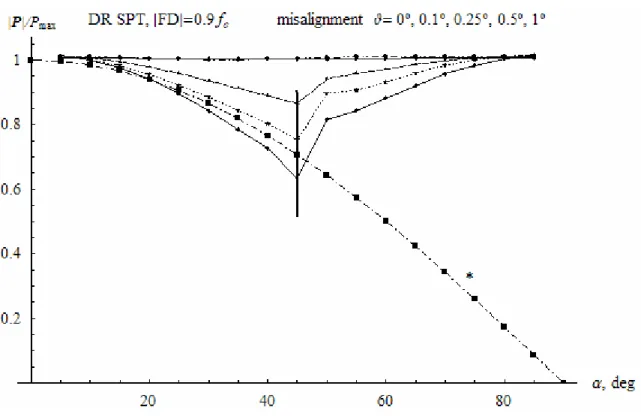
on D, and then some part of it begins to miss the director. Finally, D misses the most part of the incoming light and the sailcraft becomes uncontrollable. A similar effect occurs in the DR SPT. However, analysis of the light path in case of a slight misalignment of a sailcraft leads us to conclude that SSPT is more robust with respect to these perturbations. It can be shown that DRSPT loses controllability for smaller misalignments and hence requires much more accurate attitude control system.
Figures 3 and 4 show the results of simulation in case of a small misalignment for the SSPT and DR SPT described above. The asterisk indicates
the curve given by (1) and (2) respectively, the vertical line indicates the critical value of the control angle when the secondary reflection on the collector occurs (lower limit for an SSPT and upper limit for a DRSPT). The propulsion force is normalized by the maximum value for a flat solar sale with the same effective area
2 2 2
max
2
(
r
E/
r
s)
R
cP
=
Φ
π
. One can notice thatDR SPT is much more sensitive with respect to the attitude orientation error. The characteristics of the developed propulsion force change rapidly with the increase of axis misalignment and for 1º attitude orientation error the controllability is lost completely.
Figure 4: The effects of DR SPT misalignment
Studying the results of simulation, one can conclude that the SSPT scheme represents significant advantages compared to DR SPT. It is lighter, simpler, possesses better dynamics characteristics. Besides, it presents lower requirements for an attitude control system when the control angle is limited by relation (3).
To find out the influence of restriction (3) on the performance of a SSPT, we studied the problem of optimal Earth-Mars transfer for two cases. For
the first simulation we used the force model (1) and imposed condition (3) on the control angle α. For the second study we used model (1) for
(
4
2 2)
/
4
tan
α
>
f
cR
cf
c−
R
c , and for(
4
2 2)
/
4
tan
α
≤
f
cR
cf
c−
R
c we completed SSPT force model by a polynomial approximation of the 4th order basing on the results of numerical analysis of the propulsion force.The results of numerical simulation show that for Rc/fc¥0.5 the use of the whole spectrum of control
angle a only slightly diminishes the manoeuvre time. For Rc/fc=1 the increase of transfer time
due to restriction (3) is 12.5%, for Rc/fc=0.5 it is
0.7% and for Rc/fc=0.25 the transfer times for two
studied cases practically coincide.
Taking into account the serious problems caused by the secondary reflections, it seems quite reasonable to use the control angles that do not through the light back to the collector, that is, α should be limited by the restriction
) R -/(4f R 4f tg
α
> c c c2 c2For these control angles, the force and torque model can be obtained analytically.
3. FORCE AND TORQUE MODEL FOR A SIMPLE SOLAR PHOTON THRUSTOR In [9] we developed a force and torque model for a SSPT with ideally reflecting surfaces. However, this sailcraft contains a collector, a large surface which should be made of a thin film and consequently can not be an ideal reflector. The other elements of the sailcraft are much smaller and can possess better optical quality. Thus we develop here a model of a SSPT with non-ideally reflecting collector. In this analysis we suppose that the director surface is ideal, and that it is small so as one could disregard the effect of its shadow.
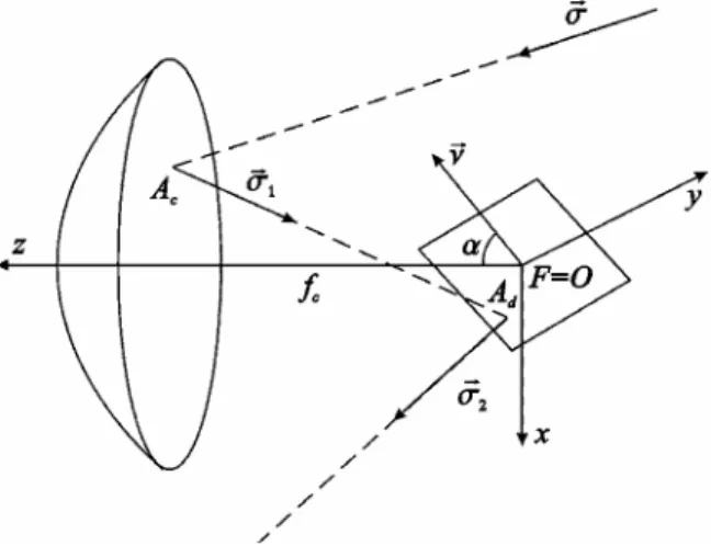
Figure 5:Scheme of reflections on SSPT with axis misalignment
To calculate the vectors of force and torque that appear due to interaction of the light with the solar photon thruster, consider a parabolic surface (Fig. 5). Its equation in the reference frame
Oxyz
(the center of mass O coincide with the focus of the paraboloid
F
) is(
)
0
,
4
2 2+
+
−
=
c cz
f
f
y
x
or(
4
)
.
4
1
f
2x
2y
2f
z
c c−
−
=
The sun light has the direction
σ
r. It is absorbed by the collector, producing forced
P
r
1 on the popint Ac of the element of the parabolic surfacedS with the position vector
ξ
r
=
x
i
r
+
y
r
j
+
z
k
r
dS
n
P
d
r
1=
−
ρ
σ
r
(
σ
r
,
r
)
.Here
ρ
=
Φ
r
E2/
r
s2 is the intensity of the light flow at this point of the orbit. The respective torque about the center of mass of the SPT O isdM
1 dP
1.
We suppose [1] that a fraction
r~
of the incident light is reflected on the element of the surface dS. A fraction s of this light is reflected specularly, and 1-s is scattered from the sail surface due to non-specular reflection.The specularly reflected light has the direction 1
σ
r n n rr r r r 2( , ) 1σ
σ
σ
= − , where 2 2 24
2
c cf
y
x
k
f
j
y
i
x
n
+
+
+
+
−
=
r
r
r
r
is the internal normal to the surface at the point
ξ
r
, andi
r
,r
j
, and kr are the Oxyz coordinate orts.This reflection of the light creates the force
dS
n
s
r
P
d
r
2r=
ρ
~
σ
r
1(
σ
r
,
r
)
.The non-specularly reflected light generates a force
dS
n
n
r
s
B
P
d
r
2s=
ρ
f(
1
−
)
~
r
(
σ
r
,
r
)
, and the re-emitted light creates a forcedS
n
n
B
B
r
P
d
b f b b f f e(
1
~
)
(
,
)
2r
r
r
r
σ
ε
ε
ε
ε
ρ
+
−
−
=
,where Bf and Bb are the surface front and back
non-Lambertian coefficients and ¶f and ¶b are the
front and back emissivities. The total force applied is e s r dP dP P d P dr2 = r2 + r2 + r2
with the torque with respect to the center of mass O given by
.
2 2d
P
M
d
r
=
ξ
r
×
r
Finally, the light is reflected on the director. Its normal is
ν
r. The size of the director is small, therefore the respective spatial angle observed from the collector is negligible. Thus we suppose that the light beam falling on D originated from the specular reflection on the collector only. The light from the point Ac of the collector isreflected at the point Ad of the director. Its
position vector can be found from the condition
(
ξ
r
,
ν
r
) (
ξ
r
τ
σ
r
,
ν
r
)
0
=
=
+
1 d A . So( )
(
,
)
,
,
1ν
σ
ν
ξ
τ
=
−
r
r
r
r
and( )
(
,
)
.
,
1 1σ
ν
σ
ν
ξ
ξ
ξ
r
=
r
−
r
r
r
r
r
d AThen the force and torque transmitted by the falling light are respectively
, ) , ( ~ 1 3 rs n dS P dr = −
ρ
σ
rσ
r r(
)
(
,
)
.
~
1 3 3dS
n
s
r
P
d
M
d
d Ar
r
r
r
r
r
r
σ
ξ
σ
ρ
ξ
×
=
×
=
The reflected light produces force and torque that can be written respectively as
,
,
)
,
(
~
4 4 2 4P
d
M
d
dS
n
s
r
P
d
d Ar
r
r
r
r
r
r
×
=
=
ξ
σ
σ
ρ
whereν
ν
σ
σ
σ
r2 = r1 −2(r1,r)ris the direction of the light reflected on the control mirror.
The created elementary force is 4 3 2 1 dP dP dP P d P dr = r + r + r + r and
∫
=
CP
d
P
r
r
.After integration we arrive at
+
+
=
224
1
ln
c c x x xf
R
P
πρ
χ
ζ
,
+
+
=
224
1
ln
c c y y yf
R
P
πρ
χ
ζ
,
+
+
=
224
1
ln
c c z z zf
R
P
πρ
χ
ζ
,where the coefficients cx, cy, cz, zx, zy, and zz are
rather cumbersome and are given in the Appendix. One can see that when an ideally reflecting SSPT is exactly oriented to the sun direction (i.e.,
σ
x=
σ
y=
0
,σ
z =1), and the control mirror rotates in the plane of the orbit (ν
x=
sin
α
,ν
y=
0
,ν
z =cosα
), the components of the light pressure force in the orbital coordinate frame OXYZ are. 2 cos ) 4 1 ln( 4 cos 2 , 0 , 2 sin ) 4 1 ln( 8 1 2 2 2 2 2 2 2 2 2 2 2 2 2 2 2 + − Φ = = + − Φ = α α π α π c c c c c s E Z Y c c c c c s E X f R R f R r r P P f R R f R r r P
Calculating the total torque due to the light pressure, after integration one obtains
(
)
[
(
)
]
}
(
)
[
(
)
]
}
(
)
, ~ 2 , ) 2 1 ( 2 ~ 4 4 4 120 ) 2 1 ( 2 ~ 4 4 4 120 2 2 2 2 2 2 2 2 2 2 2 2 2 x y y x z z c c sz x y y y x c x c c c z c c x sy y x x y x c y c c c z c c y sx s r R f M s r f f R f R f M s r f f R f R f M σ ν σ ν σ ν πρ σ ν σ ν ν σ σ υ σ πρ σ ν σ ν ν σ σ υ σ πρ − = − + + − − + Ψ − = − + − − + Ψ = where(
)
(
)
[
]
. ~ ~ ) 1 ~ ( , 4 32 4 3 64 5 4 2 2 4 2 2 b f b f b f f b b c c c c c c c s r r B r B f R f R f R fε
ε
ε
ε
ε
ε
ε
υ
+ + − + + − = Ψ + − + + =The obtained force and torque model can be used to study attitude dynamics of a SSPT.
4. SSPT ON A CIRCULAR HELIOCENTRIC ORBIT
First consider a problem of SSPT attitude dynamics on a circular heliocentric orbit. The force applied to an ideally reflecting sailcraft oriented along the sun-sailcraft direction (σx=σy=0, σz=1) and the director rotation about
the collector symmetry axis (νz=0) is
+ Φ = = = 2 22 2 2 4 1 ln 8 , 0 c c c s E Z Y X f R f r r P P P π
which means that the sail can move along a circular trajectory with the constant orbital angular velocity
+
Φ
−
=
2 2 22 3 24
1
ln
8
1
c c c E sf
R
f
m
r
r
µ
π
ω
,where µ is the gravitational parameter of the Sun, rE is the radius of the Earth orbit, rs is the radius
of the sailcraft orbit, and m is the sailcraft mass. The equations of attitude motion can be written as
.
)
(
3
)
(
,
)
(
3
)
(
,
)
(
3
)
(
32 31 3 31 33 3 33 32 3 sz s sy s sx sM
a
a
A
B
r
pq
A
B
r
C
M
a
a
C
A
r
rp
C
A
q
B
M
a
a
B
C
r
qr
B
C
p
A
+
−
=
−
+
+
−
=
−
+
+
−
=
−
+
µ
µ
µ
&
&
&
(4)Here A, B, and C are central principal moments of inertia of the sailcraft, (Msx, Msy, Msz) is the solar
radiation torque, and aij are the elements of the
transition matrix. The projections of the sailcraft absolute angular velocity onto the axes Oxyz, p, q, and r can be expressed in terms of Euler’s angles ψ, θ, and φ using rotation sequence (1;2;3) as
.
,
cos
,
sin
23 13 22 12 21 11ϕ
ω
ψ
ϕ
θ
ω
ψ
ϕ
θ
ω
ψ
&
&
&
&
&
&
+
+
=
+
+
=
+
+
=
a
a
p
a
a
q
a
a
p
According to the force and torque model for a sailcraft, the solar radiation torque acting on an ideal SSPT has the components
{
[
(
1
)
]
}
,
8
4
32 2 31 2 32 2 33 2 2 2a
a
f
a
R
a
f
R
r
r
M
x y x c c c c E sxν
ν
ν
π
−
+
−
Φ
=
{
[
(
1
)
]
}
,
8
4
31 2 32 2 31 2 33 2 2 2a
a
f
a
R
a
f
R
r
r
M
y y x c c c c E syν
ν
ν
π
−
+
+
−
Φ
=
(
32 31)
33 2 2 2 2 R f a a a r r Msz = Φ E π c c νzνx −νy .We take into account that the sailcraft is an axisymmetric body and B=A. When the director is aligned with the sailcraft symmetry axis (νx=cosβ, νy=sinβ, and νz=0), there exists an
equilibrium orientation
0
=
=
=
θ
ϕ
ψ
.System (4) possesses an integral of motion r=const. Using this integral, one can write down the characteristic equation for the equilibrium in study and obtain that the conditions of stability are not satisfied. So the problem of attitude stabilization arises.
5. ATTITUDE CONTROL FOR AN SSPT For a general problem of attitude stabilization, an attitude control system is necessary. Here we consider the use of small vanes.
For heliocentric trajectories the characteristic values of the angular accelerations due to gravity-gradient torque and orbital motion are much less that those created by cm-cp offset. To study attitude control of an SSPT along these trajectories one can consider the following problem.
Suppose the center of mass of the sailcraft is fixed. The sunlight follows in the direction of the axis OZ. The orientation of the reflector is defined by the vector
ν=(sina cosβ, sina sinβ, cosa).
Suppose there are three identical small vanes installed around the sailcraft so as the coordinates of their centers of mass are
(
)
,
−
,
=
,
,
=
0,
,
=
d d d d d d d dd
d
d
d
d
d
ϕ
π
ϕ
π
ϕ
ϕ
π
ϕ
π
ϕ
ϕ
ϕ
cos
3
2
sin
sin
3
2
cos
sin
,
cos
3
2
sin
sin
3
2
cos
sin
,
cos
sin
3 2 1r
r
r
Here
ϕ
d is the angle formed by the position vector of a vane and the sailcraft symmetry axis. The control torque produced by these vanes can be calculated as(
)
(
)
∑
=×
Φ
=
3 1 2 2 2,
i i i i s E v cn
d
n
r
r
S
M
σ
r
r
r
r
where Sv is the area of the vanes and
nr
i (i=1,2,3)are the normal vectors to their surfaces. The equations of motion become:
cz sz s cy sy s cx sx s M M a a A B r pq A B r C M M a a C A r rp C A q B M M a a B C r qr B C p A + + − = − + + + − = − + + + − = − + 32 31 3 31 33 3 33 32 3 ) ( 3 ) ( , ) ( 3 ) ( , ) ( 3 ) ( µ µ µ & & &
The linearization of this system at the equilibrium orientation satisfies the Kalman controllability condition, whenever the condition
0
≠
d
ϕ
holds. Therefore the linearized system can be stabilized by a linear feedback guaranteeing an arbitrary chosen damping rate. Varying the distance between the vanes and the sailcraft symmetry axis, one can get a control torque in wide range of values. Thus the linear feedback constructed for the linearization will also stabilize the original system.
6. CONCLUSIONS.
In this article, we developed a model of attitude dynamics of a compound solar sail. We examined two propulsion schemes of a compound solar sail, simple and double reflector solar photon thrustors. Analysis of the light path completed by the numerical simulations showed that the existent models developed for a double reflector solar photon thrustor can not provide a satisfactory force and torque description for this system. We demonstrated several advantages of a simpler scheme, one of the most important being greater robustness with respect to the attitude control errors and absence of the secondary reflections on the collector for a large and well specified interval of control angles.
It was shown that the limitation caused by attitude control requirements only slightly deteriorate the performance of an SSPT.
The force and torque model was developed for an SSPT in the case when the collector film possesses non-ideal optical properties.
We studied dynamics of an SSPT in a heliocentric circular orbit and found that its orientation towards the Sun is unstable. To control this system it is necessary to use another control device.
We have shown that for general problem of an SSPT attitude stabilization, the sailcraft can be controlled by installation of a system of vanes which can stabilize the orientation of a sail axis about the Sun-sailcraft direction.
ACKNOWLEDGEMENTS
This work is supported by Portuguese Foundation for Science and Technology -FCT (Projects
STABISAT and COMSA, POCTI/EME/58506/2004).
REFERENCES
[1] McInnes, C. R., Solar Sailing: Technology,
Dynamics and Mission Applications, Springer -
Praxis Series, Berlin, 1999, 296 pp.
[2] B.Wie. Solar sail attitude control and dynamics.
Journal of Guidance, Control and Dynamics,
27(4), 2004, 526-544.
[3] Е. Н. Polyahova, Space Flight with Solar Sail, Moscow, "Nauka", 1986, 304 pp. (in Russian). [4] Forward, R. L., Solar photon thruster, J.
Spacecraft, Vol. 27, No. 4, 1990, pp. 411- 416.
[5] McInnes, C. R., Payload mass fractions for minimum-time trajectories of flat and compound solar sails, Journal of Guidance, Control and
Dynamics, Vol. 23, No. 6, 2000, pp. 1076-1078.
[6] Mengali, G., and Quarta, A. A., Earth escape by ideal sail and solar photon thruster spacecraft,
Journal of Guidance, Control and Dynamics, Vol.
27, No. 6, 2004, pp. 1105-1108.
[7] Mengali, G., and Quarta, A. A., Time-optimal three-dimensional trajectories for Solar Photon Thruster spacecraft, Journal of Spacecraft and
Rockets, Vol. 42, No. 2, 2005, pp. 379-381.
[8] Mengali, G. and Quarta, A.A., “Compound Solar Sail with Optical Properties: Models and Performance,” Journal of Spacecraft and Rockets, Vol. 43, No. 1, 2006, pp. 239-245.
[9] Guerman, A.D., and Smirnov, G., Attitude control of Solar Photon Thruster vs Plane Solar Sail.
Advances in the Astronautical Sciences, 2006, v.
123, pp. 2635 – 2648.
APPENDIX
The propulsion force acting on an SSPT is
.
4
1
ln
,
4
1
ln
,
4
1
ln
2 2 2 2 2 2
+
+
=
+
+
=
+
+
=
c c z z z x c c y y y c c x x xf
R
P
f
R
P
f
R
P
πρ
χ
ζ
πρ
χ
ζ
πρ
χ
ζ
Here{
[
(
)
]
}
{
[
(
)
]
}
(
)
{
4
2
4
[
~
(
1
(
1
2
)
2
(
)
)
]
}
,
,
)
2
(
2
)
2
1
(
~
6
6
,
)
2
(
2
)
2
1
(
~
6
6
2 2 2 2 2 2 2 2 2 2 2 2 z y y z x x z z z z z c c c c z c z z z z x x z y y z y z y c c y c y z z z y y z x x z x z x c c x c xs
r
R
f
R
f
f
s
r
R
f
f
s
r
R
f
f
σ
σ
ν
σ
σ
ν
ν
ν
ν
σ
σ
σ
πρ
χ
σ
ν
σ
σ
ν
ν
ν
ν
σ
σ
σ
σ
λ
σ
πρ
χ
σ
ν
σ
σ
ν
ν
ν
ν
σ
σ
σ
σ
λ
σ
πρ
χ
+
+
−
−
−
+
+
Ψ
+
+
−
=
−
+
+
−
−
+
−
−
Ψ
=
−
+
+
−
−
+
−
−
Ψ
=
with(
)
(
)
[
]
,
~
~
)
1
~
(
,
4
8
16
3 2 2 2 2 b f b f b f f b b c c c c cs
r
r
B
r
B
f
R
f
R
f
ε
ε
ε
ε
ε
ε
ε
λ
+
+
−
+
+
−
=
Ψ
+
−
+
=
and[
]
[
]
[
1 3 (1 2 ) 2 ( 2 2 )]
. ~ 4 , ) 3 2 ( ) 2 1 ( ~ 8 , ) 3 2 ( ) 2 1 ( ~ 8 2 2 2 2 2 2 2 2 2 z y y z x x z z z z c z z z z x x z y y z y c y z z z y y z x x z x c x s r f s r f s r fσ
σ
ν
σ
σ
ν
ν
ν
ν
σ
πρ
ζ
σ
ν
σ
σ
ν
ν
ν
ν
σ
σ
πρ
ζ
σ
ν
σ
σ
ν
ν
ν
ν
σ
σ
πρ
ζ
+ + − − − = − + + − − = − + + − − =The torque due to the solar radiation pressure is