TCD
7, 4977–5006, 2013Liquid inclusions in young sea ice using
MRI
R. J. Galley et al.
Title Page
Abstract Introduction
Conclusions References
Tables Figures
◭ ◮
◭ ◮
Back Close
Full Screen / Esc
Printer-friendly Version Interactive Discussion
Discussion
P
a
per
|
D
iscussion
P
a
per
|
Discussion
P
a
per
|
Discuss
ion
P
a
per
|
The Cryosphere Discuss., 7, 4977–5006, 2013 www.the-cryosphere-discuss.net/7/4977/2013/ doi:10.5194/tcd-7-4977-2013
© Author(s) 2013. CC Attribution 3.0 License.
Open Access
The Cryosphere
Discussions
This discussion paper is/has been under review for the journal The Cryosphere (TC). Please refer to the corresponding final paper in TC if available.
Morphology and distribution of liquid
inclusions in young sea ice as imaged by
magnetic resonance
R. J. Galley1, B. G. T. Else1, N.-X. Geilfus1, A. A. Hare1, D. Isleifson1,5, L. Ryner4, D. G. Barber1, and S. Rysgaard1,2,3
1
Centre for Earth Observation Science, University of Manitoba, 125 Dysart Road, Winnipeg, Manitoba, R3T 2N2, Canada
2
Greenland Climate Research Center, Greenland Institute of Natural Resources, Kivioq 2, P.O. Box 570, 3900 Nuuk, Greenland
3
Department of Bioscience, Arctic Research Centre, Aarhus University, 8000 Aarhus C, Aarhus, Denmark
4
National Research Council Canada, Institute for Biodiagnostics, 435 Ellice Avenue, Winnipeg, Manitoba, R3B 1Y6, Canada
5
TCD
7, 4977–5006, 2013Liquid inclusions in young sea ice using
MRI
R. J. Galley et al.
Title Page
Abstract Introduction
Conclusions References
Tables Figures
◭ ◮
◭ ◮
Back Close
Full Screen / Esc
Printer-friendly Version Interactive Discussion
Discussion
P
a
per
|
D
iscussion
P
a
per
|
Discussion
P
a
per
|
Discuss
ion
P
a
per
|
Received: 26 August 2013 – Accepted: 23 September 2013 – Published: 8 October 2013
Correspondence to: R. J. Galley (ryan.galley@ad.umanitoba.ca)
TCD
7, 4977–5006, 2013Liquid inclusions in young sea ice using
MRI
R. J. Galley et al.
Title Page
Abstract Introduction
Conclusions References
Tables Figures
◭ ◮
◭ ◮
Back Close
Full Screen / Esc
Printer-friendly Version Interactive Discussion
Discussion
P
a
per
|
D
iscussion
P
a
per
|
Discussion
P
a
per
|
Discuss
ion
P
a
per
|
Abstract
In order to determine the morphology and distribution of liquid inclusions in young sea ice, magnetic resonance imaging of an 18 cm sea ice core was done using a Siemens 3T TIM TRIO human scanner. The sample was stored at about−20◦C until the begin-ning of a constructive interference steady state gradient echo sequence which lasted
5
four and a half min. Here we present the first three-dimensional reconstruction of a brine drainage channel network in young sea ice using magnetic resonance imaging. The magnetic resonance image sequence data presented here clearly illustrate that brine drainage channels are established relatively quickly during ice formation, and in-dicates the amount and location of vertical and horizontal fluid permeability in young
10
sea ice. A simple analysis of the image sequence reveals that magnetic resonance imaging is useful in describing the vertical profile of liquid fraction that compares well to volumes calculated for similar sea ice temperatures. Future work in this vein may include three-dimensional magnetic resonance scans of sea ice cores at in situ tem-peratures using different magnetic resonance sequences in order to improve the
ob-15
servation of inclusions, though this will necessitate both access to a scanner and the construction of a cooling system compatible with a magnetic resonance imager.
1 Introduction
Sea ice is a complex material composed of ice crystals, gas bubbles and liquid brine inclusions. The structure of sea ice varies with time, thickness, temperature and the
20
seawater composition from which it grows. The physical nature of the crystal structure of sea ice and its inclusions control its mechanical strength (e.g. Assur, 1960), and its ability to exchange heat, salt and radiation, which in turn affect the atmosphere above and the ocean below, physically, chemically and biologically (Vancoppenolle et al., 2013). Light et al. (2003) showed that the apparent optical properties of sea ice are
25
TCD
7, 4977–5006, 2013Liquid inclusions in young sea ice using
MRI
R. J. Galley et al.
Title Page
Abstract Introduction
Conclusions References
Tables Figures
◭ ◮
◭ ◮
Back Close
Full Screen / Esc
Printer-friendly Version Interactive Discussion
Discussion
P
a
per
|
D
iscussion
P
a
per
|
Discussion
P
a
per
|
Discuss
ion
P
a
per
|
properties of sea ice are governed by the size, shape, and orientation of inclusions, and therefore improved knowledge of these properties is required for interpreting sea ice scattering signatures obtained using remote sensing techniques (Tucker et al., 1992). Biologically, the distribution, morphology and connectivity of liquid inclusions of sea ice are important as they may alter species composition by excluding larger organisms,
5
thereby changing the predator-prey interactions in the food web (Fritsen et al., 1994; Krembs et al., 2000). Brine drainage channels are very important, as they are likely the sites of the bulk of the liquid convection in and out (i.e. gravity drainage) of the sea ice-seawater interface (Untersteiner, 1967; Lake and Lewis, 1970; Niedrauer and Martin, 1979; Oertling and Watts, 2004; Notz and Worster, 2008). Liquid inclusions in sea ice
10
largely determine the volumes′heat capacity and permeability (e.g. Weeks and Ackley,
1986; Golden et al., 1998, 2007), which controls bulk flow in the volume that may act to flood the sea ice surface from below, or drain the sea ice volume to the ocean (see for e.g. Vancoppenolle et al., 2007). A rule of thumb (the law of fives),which may be of use contextually in this work, was suggested by Golden et al. (1998) who surmised
15
that sea ice is effectively impermeable to brine transport when the fluid volume fraction is less than 5 % (where for a bulk salinity of 5, the critical temperature for a 5 % fluid volume fraction is about−5◦C).
Since Malmgren (1927) first described the variability of sea ice bulk salinity vertically and temporally, our knowledge and understanding of how brine is trapped and moved
20
in sea ice volumes under different physical forcing mechanisms has slowly evolved. Seawater is trapped systematically within the ice crystal matrix as seawater freezes, the amount of which depends in part on the freezing rate (and therefore the atmo-spheric temperature at the time of solidification), and in part on the initial salinity of the seawater. Generally, the rate of sea ice growth governs its bulk salinity; slow ice growth
25
TCD
7, 4977–5006, 2013Liquid inclusions in young sea ice using
MRI
R. J. Galley et al.
Title Page
Abstract Introduction
Conclusions References
Tables Figures
◭ ◮
◭ ◮
Back Close
Full Screen / Esc
Printer-friendly Version Interactive Discussion
Discussion
P
a
per
|
D
iscussion
P
a
per
|
Discussion
P
a
per
|
Discuss
ion
P
a
per
|
(1983) derived the equations for gas and brine volumes in sea ice which are still widely employed today.
Untersteiner (1967) showed that the difference in sea ice bulk salinity from seawater (∼35 parts per thousand) was attributable to both its initial formation as well as by sub-sequent gravity drainage and/or thermal expulsion of liquid brine from the ice volume
5
with time. Dye tracer experiments by Bennington (1967) revealed that brine rejection during initial formation dominated but also showed that sea ice that is 20 cm thick con-tains an average of one drainage channel per 800 cm2 surface area. Brine drainage channels formed during ice growth (termed first-generation drainage channels) were found as conically shaped, interconnected networks of brine pockets between platelets
10
(Bennington, 1967). The same study indicates that there occurs a second type (which they termed second-generation brine drainage channels) with similar morphology but characteristic of sea ice deterioration.
Further work on the salt rejection during sea ice growth by Lake and Lewis (1970) working in Cambridge Bay, N.W.T., Canada in February and March of 1968 showed
15
that sea ice near the seawater interface was partly composed of vertical tubular struc-tures attended at angles of 40◦– 54◦by smaller tributary channels which often followed
crystal boundaries. That range of angles was later expanded to 30◦– 60◦by Niedrauer and Martin (1979). Later, Kovacs (1996) measured brine tributary channel angles of ∼45◦ from the vertical and similar observations in young sea ice were made by Cole
20
and Shapiro (1998). These “starburst patterns” when looked on from above, had a mean diameter of 4 cm and the individual feeder channels were 2–3 cm long and 2– 8 mm in diameter (Lake and Lewis, 1970, see their Figs. 6 and 8) and corroborated in a laboratory ice growth experiment by Eide and Martin (1975). These results are important because they showed the potential for horizontal brine movement within sea
25
TCD
7, 4977–5006, 2013Liquid inclusions in young sea ice using
MRI
R. J. Galley et al.
Title Page
Abstract Introduction
Conclusions References
Tables Figures
◭ ◮
◭ ◮
Back Close
Full Screen / Esc
Printer-friendly Version Interactive Discussion
Discussion
P
a
per
|
D
iscussion
P
a
per
|
Discussion
P
a
per
|
Discuss
ion
P
a
per
|
warm in situ, though Light et al. (2003) may have re-opened the debate on the exis-tence of micro-cracks. The mean spacing of large vertical drainage channels in one study was one channel per 180 cm2(with a mean spacing of 13.4 cm) over a sample area of 1 m2(Lake and Lewis, 1970), although the spacing of these main vertical chan-nels appeared to be variable. Wakatsuchi (1983) noted that the spatial density of these
5
channels increases (in part) with faster ice growth rates. Lake and Lewis (1970) also found the largest, most well developed inclusions exist in the bottom 20 cm of their ice samples, noting that higher, diffuse structures were most likely remnants left by past ice growth. Narrowing of the main vertical channel (termed “necking”), nearest the sea ice-seawater interface was observed by Eide and Martin (1975) and was attributed to
10
convective instability.
Instead of looking at vertical sea ice sections, Perovich and Gow (1996) chose to make horizontal thin sections of young sea ice (ice thickness=20 cm) from a spring study of Arctic lead ice in order to characterize the distribution of sea ice inclusions. More numerous and larger sized brine inclusions were found nearer the bottom of the
15
sea ice volume (up to three inclusions per mm2with an average area of 0.060 mm2 at one centimeter from the ice bottom) leading to the conclusion that temperature is the principle control on the size and shape of these inclusions (Perovich and Gow, 1996; Eicken et al., 2000; Light et al., 2003).
In addition to the original methods of sea ice microstructural thick- and thin-section
20
photography, other methods have been employed to try and characterize the morphol-ogy of inclusions in sea ice. A casting technique was explored by Weissenberger et al. (1992) where brine was removed from sea ice samples by centrifuge and then a resin was used to fill drained brine channels and subsequently hardened by UV light. Thin section samples were subsequently photographed using a scanning electron
mi-25
TCD
7, 4977–5006, 2013Liquid inclusions in young sea ice using
MRI
R. J. Galley et al.
Title Page
Abstract Introduction
Conclusions References
Tables Figures
◭ ◮
◭ ◮
Back Close
Full Screen / Esc
Printer-friendly Version Interactive Discussion
Discussion
P
a
per
|
D
iscussion
P
a
per
|
Discussion
P
a
per
|
Discuss
ion
P
a
per
|
sea ice samples as they warmed. A main impetus for these types of casting and/or imaging techniques is the inability of thin section photographic analysis to quantify sea ice inclusions in three-dimensions. Eicken et al. (2000) suggested that MRI as a method may be considered as good or better than microstructural thin section analysis provided a pixel size of < 1 mm and a slice thickness less than or equal to 0.4 mm.
5
Here we present the first three-dimensional reconstruction of a brine drainage chan-nel network in young sea ice using magnetic resonance imaging. By applying this novel technique to a relatively under-sampled ice type, our objectives are to determine: (1) whether MR images can identify the amount and location of fluid inclusions in sea ice in three dimensional space; (2) whether liquid inclusions identified by MR images are
con-10
sistent with the brine volume-temperature relationships proposed by Cox and Weeks (1983) and the “law of fives” of sea ice permeability proposed by Golden et al. (1998); and (3) to investigate brine channel formation and morphology in very young sea ice.
2 Methods
In December 2011 and January 2012, a sea ice growth experiment was conducted
15
at the Sea-ice Environmental Research Facility (SERF) at the University of Manitoba, in Winnipeg, Manitoba, Canada. The SERF is an 18.2 m (length) by 9.1 m (width) by 2.75 m (depth) outdoor pool filled with artificial seawater similar in composition to nat-ural average seawater (see Hare et al., 2013 for a chemical analysis of the seawater composition, after Millero, 2006) to an approximate operating volume of 425 m3. The
20
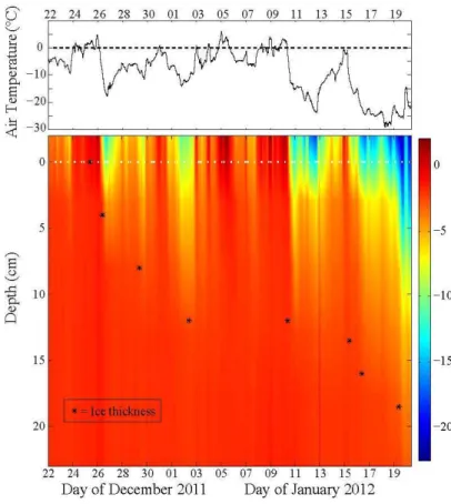
pool was kept ice-free until the start of the experiment using a closed-loop glycol heat-ing system installed on the bottom. Through exposure to ambient winter conditions, sea ice was formed. The 2 m air temperature over the pool surface was recorded using a Vaisala HMP45C probe enclosed in a radiation shield connected to an automated station logger (Fig. 1). Seawater and later sea ice and seawater temperatures through
25
ther-TCD
7, 4977–5006, 2013Liquid inclusions in young sea ice using
MRI
R. J. Galley et al.
Title Page
Abstract Introduction
Conclusions References
Tables Figures
◭ ◮
◭ ◮
Back Close
Full Screen / Esc
Printer-friendly Version Interactive Discussion
Discussion
P
a
per
|
D
iscussion
P
a
per
|
Discussion
P
a
per
|
Discuss
ion
P
a
per
|
mocouples (Omega Engineering, USA) placed in the pool at 5 cm intervals from 0 to 1.2 m and at 20 cm intervals from 1.2 m to 2.4 m (Fig. 1).
On 20 January 2012, sea ice core samples were extracted from the SERF pool using a Kovacs Mark II ice coring system (nominal 9 cm diameter, Kovacs Enterprises, Lebanon NH). One core sample was cut into 2 cm sections (analogous to horizontal
5
thick sections), which were melted in sealed buckets. The bulk salinity of the sea ice was determined by measuring the conductivity and temperature of the melt using a Hach SensION 5 conductivity probe (temperature accuracy=±0.3◦C from 0 to 70◦C, conductivity accuracy=±0.5 % full-scale, salinity accuracy=±0.1 ppt). A second core sample was used to determine the sea ice temperature at the mid-point of each 2 cm
10
thickness subsample using a digital thermometer (Traceable Control Company, Model 4000, accuracy =±0.05◦C). Using the in situ temperatures and bulk salinity values obtained from the first two cores on 20 January 2012, the brine volume was calculated using the equations of Cox and Weeks (1983) assuming a constant sea ice density of 917 kg m−3. A third core was retrieved and was immediately stored horizontally at
15
−20◦C for MR imaging.
A Siemens 3T TIM TRIO human MRI scanner (Siemens Medical Solutions, Inc., Germany) located at the Canadian National Research Council (NRC) Institute for Bio-diagnostics was employed to image one of the sea ice core samples on 20 March 2012. The sea ice core sample was stored horizontally at−20◦C following its
extrac-20
tion from the SERF, then eventually (two months later) transported in a cooler filled with ice packs to the NRC Institute for Biodiagnostics MRI facility (also in Winnipeg) where it was placed in the MR scanner. The sample spent about 45 min in the cooler prior to being imaged. The sea ice core sample was put inside the magnet wrapped in chilled (−20◦C) towel then placed in a standard “head” imaging coil. The towel served
25
TCD
7, 4977–5006, 2013Liquid inclusions in young sea ice using
MRI
R. J. Galley et al.
Title Page
Abstract Introduction
Conclusions References
Tables Figures
◭ ◮
◭ ◮
Back Close
Full Screen / Esc
Printer-friendly Version Interactive Discussion
Discussion
P
a
per
|
D
iscussion
P
a
per
|
Discussion
P
a
per
|
Discuss
ion
P
a
per
|
pulses, which are then combined to create high resolution 3-dimensional images. The principle advantage of the 3D CISS sequence is its combination of high signal levels and extremely high spatial resolution. A repetition time (TR) of 5.93 ms and an echo time (TE) of 2.83 ms were employed, yielding a total scanning time of about 4 min and 30 sec. Although much longer TR and TE have been employed previously to image sea
5
ice samples (in part to characterize temporal changes and in part to maximize resolu-tion, see for e.g. Eicken et al., 2000) it was necessary to keep the scanning time very short as a result of the lack of refrigeration for the sample within the MR instrument. Each of the 72 images integrated a volume (i.e. slice thickness (Z-plane, pages)) of 0.4 mm. The vertical (Y-plane, rows) and horizontal (X-plane, columns) resolution of
10
each image was 320 by 240. The total height (Y) of each image was 199.3 mm and the total width (X) of each image was 149.41 mm resulting in a two-dimensional pixel resolution of 0.623 mm×0.623 mm (=0.388 mm2). Given the image slice thickness of 0.4 mm (Z), the voxel (three-dimensional pixel) resolution was 0.155 mm3. Using a 72-image sequence limited the imaging to a thickness of 28.8 mm in the middle of a core
15
sample with a 9 cm diameter, which was beneficial because it precluded the imagery of most liquid that might have formed on much of the outside of the core as a result of the core being at ambient room temperature (20◦C) for a few minutes before the scan and
for the duration of the scan. The 72 images were exported from the Siemens scanner in DICOM format, and then analyzed using a combination of OsiriX and Matlab software.
20
Due to the interaction of the magnetic field with protons (water) not locked in an ice matrix, the resulting MR images are a representation of liquid content with voxel values expressed as digital numbers (DN). In an attempt quantify the liquid fraction of the sea ice core sample using MR image data the following method was constructed. The dis-tribution of voxel DNs showed a clear saturation at DN=39, which we identified as the
25
maximum voxel return,Vmax. As we will show in 3.3, several of the liquid water
TCD
7, 4977–5006, 2013Liquid inclusions in young sea ice using
MRI
R. J. Galley et al.
Title Page
Abstract Introduction
Conclusions References
Tables Figures
◭ ◮
◭ ◮
Back Close
Full Screen / Esc
Printer-friendly Version Interactive Discussion
Discussion
P
a
per
|
D
iscussion
P
a
per
|
Discussion
P
a
per
|
Discuss
ion
P
a
per
|
voxel DN (VDN) can be estimated via:
Lf =
VDN Vmax
×100 (1)
We calculated the liquid water fraction for every voxel, and then averaged each of the 310 horizontal planes to create a liquid volume profile. This is analogous to a brine vol-ume profile derived using temperature and bulk salinity measurements from a
tradition-5
ally sectioned core, but at a much finer (0.623 mm thickness) resolution. We calculated brine volume following Cox and Weeks (1983) using bulk salinity from the duplicate core and compared the liquid volume profile. Since the sea ice core temperature was about−20◦C when imaged, we calculated brine volume at that temperature throughout the core. We also calculated the brine volume assuming−18◦C and−15◦C, because
10
the core may have warmed slightly from−20◦C during transport from freezer storage to the MR scanner. A contrast agent such as copper sulphate (CuSO4, see for e.g. Eicken et al., 2000) could have been added to the seawater prior to the sea ice growth to aid in the illumination of liquid by the MR scanner, but this was not the only project taking place at SERF during winter 2011–2012 and it was agreed that no superfluous
15
chemicals be added to the seawater in the pool.
3 Results
3.1 Environmental conditions and ice growth
The experiment began on 22 December 2011 when the pool was allowed to cool by turning offthe heating system at its bottom. At that time the air temperature was−5◦C
20
TCD
7, 4977–5006, 2013Liquid inclusions in young sea ice using
MRI
R. J. Galley et al.
Title Page
Abstract Introduction
Conclusions References
Tables Figures
◭ ◮
◭ ◮
Back Close
Full Screen / Esc
Printer-friendly Version Interactive Discussion
Discussion
P
a
per
|
D
iscussion
P
a
per
|
Discussion
P
a
per
|
Discuss
ion
P
a
per
|
thickness in the pool continued to increase until about 3 January 2012, when it reached 12 cm, at which point the air temperature fluctuated near 0◦C during the following week, warming the sea ice volume and resulting in zero net ice growth until about 10 January 2012 (Fig. 2). This warm period created an ice volume that was near isothermal near its freezing point (∼ −2◦C) on 16 January (though cooler in the surface 2-cm layer, around
5
−3◦C) with near-constant calculated brine volumes of slightly less than 10 % (Hare et al., 2013). The air temperature began to decrease on 11 January reaching−22◦C near midnight on 12 January (Fig. 2). This cold snap caused the sea ice volume to cool, but it took until the morning of 15 January to reach 13.5 cm, a thickness increase of only 1.5 cm in almost four days due mostly to the amount of heat that needed to be
ex-10
tracted from the volume before growth could occur at the bottom of the ice. Early on 15 January the air temperature increased rapidly to near 0◦C (Fig. 2) causing a rapid
in-crease in the sea ice temperature that day (Fig. 2). Finally, between 16 and 20 January plummeting air temperatures grew 5 cm of sea ice. During this relatively short period, the ambient air temperature fluctuated greatly, and therefore so did temperatures within
15
the growing ice volume (Fig. 2).
3.2 Sea ice core sample temperature, bulk salinity and brine volume
The sea ice samples taken from the SERF on 20 January 2012 were about 18 cm thick, though an analysis of all the cores taken over the experiment suggest some spatial variation (±0.5 to 1.0 cm) in the sea ice thickness within the facility. Figure 3 shows the
20
in situ temperature of the sea ice sample (dashed line) at the midpoint of 2 cm thick salinity sub-sample intervals on 20 January. Several days of air temperatures less than −20◦C had created a temperature gradient from−5.4◦C at the surface of the sea ice to−2.3◦C nearest the sea ice-seawater interface. Of note in the sea ice temperature profile is a near-surface warm inflection in the curve near a depth of 4 cm (Fig. 3) that
25
is likely a product of diurnal warming.
lay-TCD
7, 4977–5006, 2013Liquid inclusions in young sea ice using
MRI
R. J. Galley et al.
Title Page
Abstract Introduction
Conclusions References
Tables Figures
◭ ◮
◭ ◮
Back Close
Full Screen / Esc
Printer-friendly Version Interactive Discussion
Discussion
P
a
per
|
D
iscussion
P
a
per
|
Discussion
P
a
per
|
Discuss
ion
P
a
per
|
ers (Fig. 3). The bulk salinity of the top-most 2 cm layer was 5.7 from which it decreased to 3.6 in the 6–8 cm layer, before increasing with depth to 4.7 in the 10–12 cm layer. In the bottom three 2 cm sections of the core sample the bulk salinity increased from 4.6 to 5.8 to 12.1 respectively (Fig. 3).
The calculated sea ice brine volume curve is shaped similarly to the bulk salinity
5
curve, though the top part of the brine volume curve is more vertical as the brine volumes are shrunken at the surface by colder ice temperatures (Fig. 3). The calculated brine volume in the 0–2 cm layer is 5.8 %, and the inflection toward larger bulk salinity values with a maximum in the 10–12 cm layer is also reflected in the brine volume (6.0 %) eventually increasing to 22.5 % in the bottommost 2 cm layer (Fig. 3).
10
The sea ice core obtained from SERF on 20 January 2012 was almost completely warmer than−5◦C in situ (Fig. 3) save for the top-most 2 cm layer. Furthermore, the layers between 2 and 8 cm thickness had low bulk salinity and brine volumes less than 5 % (4.3 %, 4.3 % and 4.2 % in the 2 cm sections between 2 and 8 cm depth respec-tively) (Fig. 3).
15
3.3 MRI results
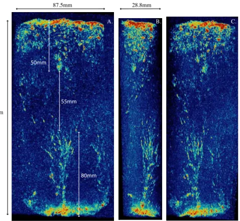
The high resolution three-dimensional CISS gradient echo image sequence obtained from the MR scanner is shown (Fig. 4).
These images are instructive in describing the morphology and location of liquid in-clusions in the sea ice core sample. For the purposes of this general description of
20
the distribution of liquid inclusions, we divide the core into three sections in the vertical (Fig. 4). The top section is about 50 mm thick and is comprised mainly of spherical inclusions that are randomly distributed and less than 2 mm in diameter, though a few are as large as 3 mm in diameter. The middle section of the core is about 55 mm thick, and contains very few imaged inclusions. Inclusions in this section are generally
elon-25
TCD
7, 4977–5006, 2013Liquid inclusions in young sea ice using
MRI
R. J. Galley et al.
Title Page
Abstract Introduction
Conclusions References
Tables Figures
◭ ◮
◭ ◮
Back Close
Full Screen / Esc
Printer-friendly Version Interactive Discussion
Discussion
P
a
per
|
D
iscussion
P
a
per
|
Discussion
P
a
per
|
Discuss
ion
P
a
per
|
bottom of the sea ice core and is 40 mm at its widest point, 65 mm from the bottom of the core. It is asymmetric in terms of the volume of ice it interacts with, that is to say it is wider in the X-plane than it is in the Z-plane (Fig. 4). It takes the classical shape of a “river attended to by its tributaries” (after Lake and Lewis, 1970) in the vertical, with the attending channels and elongated pockets intersecting the main vertical channel
5
at angles less than 35◦(all angles are from the vertical), though there is one channel about 30 mm in length which connects at an angle of approximately 55◦(Fig. 4). These attending channels were measured individually using OsiriX software and found to be within 0.80 mm and 1.3 mm in diameter and the largest measured 1.5 mm across. It should be noted that although we refer to the main drainage channel (especially in the
10
bottom∼30 mm of the sea ice) as vertical, it is offset from the vertical by 3–5◦ . The
speed with which the brine drainage channel feature imaged here was generated was less than six days, as the sea ice in the SERF pond was 13.5 cm thick on 15 January and grew > 18 cm thick on 20 January 2012 (Fig. 2).
To further describe the position and distribution of the inclusions in the sea ice core
15
sample, horizontal sub sections (240 (X)×72 (Z) pixels) using the sum of 6 image rows (Y) were constructed (Fig. 5). In the top section (56.07 mm, 90 rows, Fig. 5a), we ob-serve small spherical and elongated linear inclusions in the first 29.90 mm of the sea ice core (Fig. 5a). The inclusions above 29.90 mm depth do not appear to be verti-cally developed by more than the thickness of one MR sub section (3.738 mm, the
20
sum of 6 horizontal slices) in Fig. 5a. Between 29.90 mm and 48.59 mm, the imaged inclusions are mainly spherical and larger than those in the top 29.90 mm; the largest inclusion, most easily seen in MR sections centered on 37.38 and 41.12 mm (Fig. 5a) is 5.5–6.5 mm in diameter. Above this inclusion and centered on 33.64 mm, there are several similar inclusions, though not quite as large, with diameters between 3.5 and
25
TCD
7, 4977–5006, 2013Liquid inclusions in young sea ice using
MRI
R. J. Galley et al.
Title Page
Abstract Introduction
Conclusions References
Tables Figures
◭ ◮
◭ ◮
Back Close
Full Screen / Esc
Printer-friendly Version Interactive Discussion
Discussion
P
a
per
|
D
iscussion
P
a
per
|
Discussion
P
a
per
|
Discuss
ion
P
a
per
|
that the top section of the sea ice sample volume could be connected to the sea ice-seawater interface due to its granular crystal structure.
Beginning with the slice at 52.33 mm depth (Fig. 5a) and continuing downward through the middle part of the core (Fig. 5b) there occur almost no obvious inclusions of the same magnitude as those in the top section in the MR image series, which makes
5
sense in the context of the relatively low bulk salinity and brine volume at these depths (Fig. 3). The sea ice growth rate in SERF was relatively low; 12 cm of sea ice grew between 25 December 2011 and 2 January 2012 (∼9 days) following a capping of the SERF pool with granular dark nilas (e.g. Fig. 1) as a result of the ambient air tempera-tures (Fig. 2). Therefore, we see relatively low sea ice bulk salinities (Fig. 3) and almost
10
no imaged inclusions (Fig. 4, Fig. 5b).
In order to further characterize the brine drainage channel features that occupy in part the bottom 80 mm or so of our sea ice core sample, ten horizontal sections com-prising the sums of twelve horizontal slices are presented in Fig. 5c. The bottom-most section centered at 178.80 mm depth shows similarly oriented groups of columnar
crys-15
tal lamellae with liquid between them (Fig. 5c). In the section centered at 171.33 mm, the brine drainage channel outlet is resolved near the bottom of the sea ice core, which is 4.4 mm by 3.115 mm (13.706 mm2). In the horizontal sections at 163.85 mm and 156.37 mm depth, the brine drainage channel is seen to split in two. The brine drainage feature is then observed to branch out before taking the classical “starburst” shape in
20
the section at 133.95 mm (Fig. 5c). Above this section, the feeder arms which connect these horizontal sections vertically become more diffuse, and at 111.52 mm (Fig. 5c) they can be seen individually, above which they ‘die out” into the middle section of the core.
Using the premise that highest MRI voxel value indicates the presence of a
com-25
TCD
7, 4977–5006, 2013Liquid inclusions in young sea ice using
MRI
R. J. Galley et al.
Title Page
Abstract Introduction
Conclusions References
Tables Figures
◭ ◮
◭ ◮
Back Close
Full Screen / Esc
Printer-friendly Version Interactive Discussion
Discussion
P
a
per
|
D
iscussion
P
a
per
|
Discussion
P
a
per
|
Discuss
ion
P
a
per
|
comparable to the calculated brine volume curve for the in situ temperatures (Fig. 3) and the calculated brine volume curves for frozen horizontal sample storage tempera-tures (Fig. 6), even bearing an inflection toward higher values in the bottom half of the profile similar to the calculated brine volumes. The absolute values of the MRI-derived liquid fraction profile match well with the brine volumes calculated for the storage
tem-5
peratures (Fig. 6). The liquid fraction near the top of the core is slightly above 2 % from where it decreases to 1.50 % at 54.75 mm and then varies about 1.53 % until 70.25 mm where it begins to increase. The liquid fraction reached 1.79 % at 118.4 mm before it began to decrease to 1.65 % at 159.5 mm (Fig. 6). Finally, just as the calculated brine volume profiles, the MRI-derived profile increased rapidly between 160 mm and the
10
bottom of the core sample. It is within this 20 mm section that the greatest departure from the calculated storage brine volumes, which are much higher (Fig. 6).
4 Discussion
A young ice core of 18 cm thickness was successfully imaged in high resolution using magnetic resonance. These three-dimensional data reveal the size and shape of liquid
15
inclusions in an intact sea ice core and in part, the timing of the formation of a brine drainage channel structure connected to the seawater below. Results indicate that the imaged brine drainage channel feature in the bottom 8 cm of the sea ice volume on 20 January 2012 was formed in as little as 5 days during congelation ice growth. In that re-gard it should be deemed a first-generation channel using Bennington’s nomenclature
20
as a result of the ice volume temperature history and thickness evolution (Fig. 2) which shows that at least the bottom 6–7 cm of the sea ice volume were grown after the SERF pool had clearly undergone several temperature cycles due to warming/cooling at its surface by the ambient air temperature (Fig. 2) and solar irradiance (Bennington, 1967; Lake and Lewis, 1970, Eide and Martin, 1975). The angled but unconnected feeder
25
TCD
7, 4977–5006, 2013Liquid inclusions in young sea ice using
MRI
R. J. Galley et al.
Title Page
Abstract Introduction
Conclusions References
Tables Figures
◭ ◮
◭ ◮
Back Close
Full Screen / Esc
Printer-friendly Version Interactive Discussion
Discussion
P
a
per
|
D
iscussion
P
a
per
|
Discussion
P
a
per
|
Discuss
ion
P
a
per
|
the sea ice-seawater interface, trapped within the volume as individual inclusions. This supports the observation of Cole and Shapiro (1998) that large drainage networks with similar geometry terminate at various horizons in thick first year sea ice. Brine drainage channels photographed by Cole and Shapiro (1998) show that these features may oc-cur in almost the entire depth of sea ice up to 1.77 m thick; the time required for their
5
formation and development is integral to the evolution of the volumes’ permeability. An interesting difference between the features observed by Cole and Shapiro (1998) and those observed by Lake and Lewis (1970) is that the central vertical channel of the brine drainage features observed by Cole and Shapiro (1998) are attended by feeder arms for nearly their whole length in the vertical, however those observed here and also
10
by Lake and Lewis (1970) indicate that these feeder arms attend the vertical channel as branches do a tree trunk, with only the central vertical channel or “trunk” present in the bottom half of the brine drainage feature as a whole. Observation of these star-burst shaped feeder arms which connect at 25–30◦to a main vertical channel indicate
that some volume of sea ice (in this case slightly less than half the total thickness)
15
may experience simultaneous horizontal and vertical brine movement, which calls into question the validity of drilling blind core holes to various depths (the “sackhole” tech-nique) for sampling brine from a specific depth in sea ice. These observations seem to fall in line with the work on convection in mushy layers to explain the desalination pro-cesses of sea ice (e.g. Worster, 1997; Feltham et al., 2006; Notz and Worster, 2009).
20
In the SERF sea ice, it seems that initially the brine rejected by the formation of ice crystals remained in the interstices before being trapped by freezing and downward growth (Fig. 3). Further we provide observation of the sea ice depth reaching some critical thickness where brine is able to drain to the seawater below (e.g. Fig. 4) as a result of gravity drainage channels.
25
TCD
7, 4977–5006, 2013Liquid inclusions in young sea ice using
MRI
R. J. Galley et al.
Title Page
Abstract Introduction
Conclusions References
Tables Figures
◭ ◮
◭ ◮
Back Close
Full Screen / Esc
Printer-friendly Version Interactive Discussion
Discussion
P
a
per
|
D
iscussion
P
a
per
|
Discussion
P
a
per
|
Discuss
ion
P
a
per
|
Fig. 4) when combined with its relatively low temperature, most likely rendered the top layer impermeable to liquid transport at the time. The 2 cm layers centered at 3, 5 and 7 cm (Fig. 3) contained less bulk salinity as a result of their connection to the sea ice-seawater interface when the ice was 8–12 cm thick between 29 December 2011 and 10 January 2012 as it is possible that some brine was drained from this volume during
5
the extended warm period in the middle of the experiment (Fig. 2). However, it may be that brine contained in this region of the core sample resides between transitional and/or columnar sea ice crystals (e.g. Eicken et al., 2000) though the MR images presented here may not be high resolution enough to show them as a result of the very short scanning time employed. The increase in bulk salinity and brine volume
10
in layers centered on 11 and 13 cm (Fig. 3) likely occurred as seawater bathing the bottom of the skeletal layer of the ice when the ice was 12–13.5 cm thick for almost a week was trapped in the interstices of the ice crystals by rapid growth of the final 5 cm of sea ice between 16 and 20 January (Fig. 2). It is obvious from the MRI data that the bottom 8 cm of the sea core sample here were permeable to the seawater below
15
as a result of the observed connectivity within the multitude of branches of the brine drainage structure we have imaged. Finally, the bulk salinity and brine volume in the bottom 2 layers are typical (e.g. Cox and Weeks, 1975) of a warm skeletal ice bottom (Fig. 3) that was less than 2 days old (Fig. 2).
The connection of these brine drainage channel features to the sea ice-seawater
20
interface could have serious implications for the exchange of carbonate species be-tween sea ice and the underlying seawater (e.g. Rysgaard et al., 2012). In particular, the brine incorporated within the solid ice matrix could become supersaturated with CO2due to a concentration effect resulting from brine volume reduction (Papadimitriou
et al., 2004), which may lead to the precipitation of ikaite crystals (Rysgaard et al.,
25
2012). The associated release of CO2when ikaite precipitates may be rejected to the water column below due to the impermeability of the sea ice above this zone (e.g. Loose et al., 2011), which may explain the under-sea ice increase in pCO2 to
TCD
7, 4977–5006, 2013Liquid inclusions in young sea ice using
MRI
R. J. Galley et al.
Title Page
Abstract Introduction
Conclusions References
Tables Figures
◭ ◮
◭ ◮
Back Close
Full Screen / Esc
Printer-friendly Version Interactive Discussion
Discussion
P
a
per
|
D
iscussion
P
a
per
|
Discussion
P
a
per
|
Discuss
ion
P
a
per
|
formation and dissolution of ikaite crystals is a dynamic process in sea ice depending on the sea ice temperature. Much of the young ice volume sampled was cold enough (−3◦C) to potentially produce ikaite crystals, and the observed brine drainage channel feature might offer them a mechanism by which to descend into the seawater below, taking their “CO2equivalent” with them. The low concentrations of ikaite near the bot-5
tom of sea ice observed by Geilfus et al. (2013) may therefore due to either the lack of crystal formation or potentially ikaite crystal export downward to the water column and their eventual dissolution.
This MR technique for visualising whole ice core samples will be further refined in the future by the addition of a temperature control unit at the imaging coil in order to
10
increase the scanning time for the sake of increased resolution and potentially scan ice cores at their in situ temperatures. It may also merit discussion to design and purpose-build an imaging coil specifically for whole ice cores.
5 Conclusions
Using a magnetic resonance scanner, a brine drainage channel feature was imaged in
15
18 cm thick young sea ice grown in an outdoor sea ice pool from experimental seawa-ter under ambient weather conditions. It is surmised that this brine drainage channel feature is a first generation one, having been formed during sea ice growth in the week previous to the sampling date, and not as result of melting processes, given the temper-ature history of the sea ice volume over the growth period of that section. The speed
20
with which the brine drainage channel feature imaged here was generated was less than 6 days.
The imaged brine drainage channel feature is 80 mm in the vertical, and 40 mm in the horizontal at its widest point, about 65 mm from the sea ice-seawater interface. The feeder arms attend the main vertical channel at angles of 25–30◦from the vertical and
25
TCD
7, 4977–5006, 2013Liquid inclusions in young sea ice using
MRI
R. J. Galley et al.
Title Page
Abstract Introduction
Conclusions References
Tables Figures
◭ ◮
◭ ◮
Back Close
Full Screen / Esc
Printer-friendly Version Interactive Discussion
Discussion
P
a
per
|
D
iscussion
P
a
per
|
Discussion
P
a
per
|
Discuss
ion
P
a
per
|
The size and shape of this imaged feature indicate that horizontal as well as vertical heat and salt fluxes are possible and indeed probable within the bottom section of the sea ice core analyzed.
The MR image data, after having been compared to the sea ice temperature, bulk salinity and brine volume in the context of percolation theory (after Golden et al., 1998)
5
lends credibility to the “law of fives” showing that the top and middle sections (∼110 mm of∼180 mm total thickness) of the ice sampled imaged are not connected to the sea ice-seawater interface, while the bottom section (∼80 mm) of the sea ice volume may be connected vertically and to some extent horizontally within the volume to the sea ice-seawater interface.
10
Acknowledgements. The Canada Excellence Research Chair program (CERC, SR), the Canada Resarch Chair program (CRC, DB) and the Natural Sciences and Engineering Re-search Council (NSERC) of Canada (DB) contributed funding to this study. SERF was funded by the Canada Foundation of Innovation (CFI), the Canadian Excellence Research Chair pro-gram (SR), the Manitoba Research and Innovation Fund, and the University of Manitoba. We 15
are grateful to Patricia Dreessen de Gervai for her time and willingness to attempt magnetic resonance imaging of an ice core without reservation. This work is a contribution to the Arctic Science Partnership (ASP) and the ArcticNet Networks of Centres of Excellence programs.
References
Assur, A.: Composition of sea ice and its tensile strength, US Army snow ice and permafrost 20
research establishment, research report 44, corps of engineers, Wilmette, Illinois, December 1960.
Bennington, K. O.: Desalination features in natural sea ice, J. Glaciol., 6, 845–857, 1967 Cole, D. M. and Shapiro, L. H.: Observations of brine drainage networks and microstructure of
first-year sea ice, J. Geophys. Res., 103, 21739–21750, 1998. 25
TCD
7, 4977–5006, 2013Liquid inclusions in young sea ice using
MRI
R. J. Galley et al.
Title Page
Abstract Introduction
Conclusions References
Tables Figures
◭ ◮
◭ ◮
Back Close
Full Screen / Esc
Printer-friendly Version Interactive Discussion
Discussion
P
a
per
|
D
iscussion
P
a
per
|
Discussion
P
a
per
|
Discuss
ion
P
a
per
|
Cox, G. F. N. and Weeks, W. F.: Equations for determining the gas and brine volumes in sea ice samples, J. Glaciol., 29, 306–316, 1983.
Ehn, J. K., Hwang, B.-J., Galley, R., and Barber, D. G.: Investigations of newly forming sea ice in the Cape Bathurst polynya: 1. Structural, physical and optical properties, J. Geophys. Rese., 112, C05002, doi:10.1029/2006JC003703, 2007.
5
Eicken, H., Bock, C., Wittig, R., Miller, H., and Poertner, H.-O.: Magnetic resonance imaging of sea-ice pore fluids: methods and thermal evolution of pore microstructure, Cold Reg. Sci. Technol., 31, 207–225, 2000.
Eide, L. I. and Martin, S.: The formation of brine drainage features in young sea ice, J. Glaciol., 14, 137–154, 1975.
10
Else, B. G. T., Papakyriakou, T. N., Galley, R. J., Mucci, A., Gosselin, M., Miller, L. A., Shadwick, E. H., and Thomas, H.: Annual cycles of pCO2sw in the southeastern Beaufort Sea: New understandings of air-sea CO2 exchange in arctic polynya regions, J. Geophys. Res., 117, C00G13, doi:10.1029/2011JC007346, 2012.
Feltham, D. L., Untersteiner, N., Wettlaufer, J. S., and Worster, M. G.: Sea ice is a mushy layer, 15
Geophys. Res. Lett., 33, L14501, doi:10.1029/2006GL026290, 2006.
Fritsen, C. H., Lytle, V. I., Ackley, S. F., and Sullivan, C. W.: Autumn bloom of Antarctic pack-ice algae, Science, 266, 782–784, 1994.
Geilfus, N.-X., Carnat, G., Dieckmann, G. S., Halden, N., Nehrke, G., Papakyriakou, T., Tison, J. L., and Delille, B.: First estimates of the contribution of CaCO3precipitation to the release 20
of CO2 to the atmosphere during young sea ice growth, J. Geophys. Res., 118, 244–255, doi:10.1029/2012JC007980, 2013.
Golden, K. M., Ackley, S. F., and Lytle, V. I.: The percolation phase transition in sea ice, Science, 282, 2238, doi:10.1026/science.282.5397.2238, 1998.
Golden, K. M., Eicken, H., Heaton, A. L., Miner, J., Pringle, D. J., and Zhu, J.: Thermal 25
evolution of permeability and microstructure in sea ice, Geophys. Res. Lett., 34, L16501, doi:10.1029/2007GL030447, 2007.
Hare, A. A., Wang, F., Barber, D., Geilfus, N.-X., Galley, R. J., and Rysgaard, S.: pH evo-lution in sea ice grown at an outdoor experimental facility, Mar. Chem., 154, 46–54, doi:10.1016/j.marchem.2013.04.007, 2013.
30
TCD
7, 4977–5006, 2013Liquid inclusions in young sea ice using
MRI
R. J. Galley et al.
Title Page
Abstract Introduction
Conclusions References
Tables Figures
◭ ◮
◭ ◮
Back Close
Full Screen / Esc
Printer-friendly Version Interactive Discussion
Discussion
P
a
per
|
D
iscussion
P
a
per
|
Discussion
P
a
per
|
Discuss
ion
P
a
per
|
Krembs, C., Gradinger, R., and Spindler, M.: Implications of brine channel geometry and sur-face area for the interaction of sympagic organisms in Arctic sea ice, J. Exp. Mar. Biol. Ecol., 243, 55–80, 2000.
Lake, R. A. and Lewis, E. L.: Salt rejection by sea ice during growth, J. Geophys. Res., 75, 583–597, 1970.
5
Light, B., Maykut, G. A., and Grenfell, T. C.: Effects of temperature on the microstructure of first-year Arctic sea ice, J. Geophys. Res., 108, 3051, doi:10.1029/2001JC000887, 2003. Loose, B., Schlosser, P., Perovich, D., Ringelberg, D., Ho, D. T., Takahashi, T., Richter-Menge,
J., Reynolds, C. M., McGillis, W. R., and Tison, J. L.: Gas diffusion through columnar labora-tory sea ice: implications for mixed-layer ventilation of CO2in the seasonal ice zone, Tellus, 10
63B, 23–39, 2011.
Malmgren, F.: On the properties of sea ice. The Norwegian North Polar Expedition with the “Maud” 1918–1925 scientific results, 1, 1927.
Millero, F. J.: Chemical Oceanography, CRC Press, 30, 2006.
Nakawo, M. and Sinha, N. K.: Growth rate and salinity profile of first-year sea ice in the high 15
Arctic, J. Glaciol., 27, 315–330, 1981.
Niedrauer, T. M. and Martin, S.: An experimental study of brine drainage and convection in young sea ice, J. Geophys. Res., 84, 8C1208, 1176–1186, 1979.
Notz, D. and Worster, M. G.: In situ measurements of the evolution of young sea ice, J. Geophys. Res., 113, C03001, doi:10.1029/2007JC004333, 2008.
20
Notz, D. and Worster, M. G.: Desalination processes of sea ice revisited, J. Geophys. Res., 114, C05006, doi:10.1029/2008JC004885, 2009.
Oertling, A. B. and Watts, R. G.: Growth of and brine drainage from NaCl-H2O freezing: A simulation of young sea ice, J. Geophys. Res., 109, C04013, doi:10.1029/2001JC001109, 2004.
25
Papadimitriou, S., Kennedy, H., Kattner, G., Dieckmann, G. S., and Thomas, D. N.: Experi-mental evidence for carbonate precipitation and CO2 degassing during sea ice formation, Geochimica et Cosmochimica Acta, 68, 1749–1761, 2004.
Perovich, D. K. and Gow, A. J.: A quantitative description of sea ice inclusions, J. Geophys. Res., 101, 18327–18343, 1996.
30
TCD
7, 4977–5006, 2013Liquid inclusions in young sea ice using
MRI
R. J. Galley et al.
Title Page
Abstract Introduction
Conclusions References
Tables Figures
◭ ◮
◭ ◮
Back Close
Full Screen / Esc
Printer-friendly Version Interactive Discussion
Discussion
P
a
per
|
D
iscussion
P
a
per
|
Discussion
P
a
per
|
Discuss
ion
P
a
per
|
Tucker, W. B. I., Perovich, D. K., Gow, A. J., Weeks, W. F., and Drinkwater, M. R.: Physical properties of sea ice relevant to remote sensing, in: Microwave Remote Sensing of Sea Ice, 68, Washington, DC, Ch. 2, AGU, 1992.
Untersteiner, N.: Natural desalination and equilibrium salinity profile of perennial sea ice, J. Geophys. Res., 73, 1251–1257, 1967.
5
Vancoppenolle, M., Bitz, C. M., and Fichefet, T.: Summer landfast sea ice desalination at Point Barrow, Alaska: modeling and observations, J. Geophys. Res., 112, C04022, doi:10.1029/2006JC003493, 2007.
Vancoppenolle, M., Meiners, K. M., Michel, C., Bopp, L., Brabant, F., Carnat, G., Delille, B., Lannuzel, D., Madec, G., Moreau, S., Tison, J.-L., and van der Merwe, P.: Role of sea 10
ice in global biogeochemical cycles: emerging views and challenges, Quaternary Sci. Rev., doi:10.1016/j.quascirev.2013.04.011,in press, 2013.
Wakatsuchi, M.: Brine exclusion process from growing sea ice, Contribution No. 2627 from the Institute of Low Temperature Science, A33, 29–65, Sapporo, Japan, 1983.
Weeks, W. F. and Ackley, S. F.: The growth, structure, and properties of sea ice, US Army Cold 15
Regions Research and Engineering Laboratory Monograph 82–1, 130 pp., Hanover, NH, 1982.
Weeks, W. F. and Ackley, S. F.: The growth, structure and properties of sea ice, in: The Geo-physics of Sea ice, edited by: Untersteiner, N., 9–164, Plenum, New York, NY, 1986.
Weissenberger, J., Dieckmann, G., Gradinger, R., and Spindler, M.: Sea ice: A cast technique 20
to examine and analyze brine pockets and channel structure, Limnol. Oceanogr., 37, 179– 183, 1992.
TCD
7, 4977–5006, 2013Liquid inclusions in young sea ice using
MRI
R. J. Galley et al.
Title Page
Abstract Introduction
Conclusions References
Tables Figures
◭ ◮
◭ ◮
Back Close
Full Screen / Esc
Printer-friendly Version Interactive Discussion
Discussion
P
a
per
|
D
iscussion
P
a
per
|
Discussion
P
a
per
|
Discuss
ion
P
a
per
|
−5 −4 −3 −2
0
2
4
6
8
10
12
14
16
18
Temp (°C)
Depth (cm)
0 5 10 15 20 25
Brine Volume (%)
2.5 5 7.5 10 12. 5
Salinity
Temperature Bulk salinity Brine volume
Figure 3
Fig. 3.Sea ice temperature, salinity and brine volume (calculated using a density of 917 kg m−3) on 20 January 2012 through a sea ice thickness of 18 cm.
TCD
7, 4977–5006, 2013Liquid inclusions in young sea ice using
MRI
R. J. Galley et al.
Title Page
Abstract Introduction
Conclusions References
Tables Figures
◭ ◮
◭ ◮
Back Close
Full Screen / Esc
Printer-friendly Version Interactive Discussion
Discussion
P
a
per
|
D
iscussion
P
a
per
|
Discussion
P
a
per
|
Discuss
ion
P
a
per
|
185mm
87.5mm 28.8mm
A. B. C.
50mm
55mm
80mm
TCD
7, 4977–5006, 2013Liquid inclusions in young sea ice using
MRI
R. J. Galley et al.
Title Page
Abstract Introduction
Conclusions References
Tables Figures
◭ ◮
◭ ◮
Back Close
Full Screen / Esc
Printer-friendly Version Interactive Discussion
Discussion
P
a
per
|
D
iscussion
P
a
per
|
Discussion
P
a
per
|
Discuss
ion
P
a
per
|
Fig
TCD
7, 4977–5006, 2013Liquid inclusions in young sea ice using
MRI
R. J. Galley et al.
Title Page
Abstract Introduction
Conclusions References
Tables Figures
◭ ◮
◭ ◮
Back Close
Full Screen / Esc
Printer-friendly Version Interactive Discussion
Discussion
P
a
per
|
D
iscussion
P
a
per
|
Discussion
P
a
per
|
Discuss
ion
P
a
per
|
Figure 5c
TCD
7, 4977–5006, 2013Liquid inclusions in young sea ice using
MRI
R. J. Galley et al.
Title Page
Abstract Introduction
Conclusions References
Tables Figures
◭ ◮
◭ ◮
Back Close
Full Screen / Esc
Printer-friendly Version Interactive Discussion
Discussion
P
a
per
|
D
iscussion
P
a
per
|
Discussion
P
a
per
|
Discuss
ion
P
a
per
|
1 1.5 2 2.5 3 3.5 4 4.5
0
2
4
6
8
10
12
14
16
18
Brine Volume (%)
Depth (cm)
−15°C
−18°C
−20°C MR-derived
Fig. 6. The brine volume (after Cox and Weeks, 1983) calculated using the observed bulk salinity data (Fig. 3) and constant sample temperatures of−20◦C,