Abstract— A microstrip leaf-shaped printed monopole antenna bioinspired on the Inga marginata leaves is presented in this paper for UWB applications. A parametric study of the proposed antenna bioinspired geometry was conducted in order to verify their resonant properties. The antenna was designed with a rectangular slitted ground plane for impedance matching and fabricated on inexpensive glass fiber substrate and fed by a 50 Ω microstrip line. Numerical and experimental results were obtained. The results show an impedance bandwidth superior to 10.26 GHz, greater than the bandwidth considered UWB (7.5 GHz). Antenna dimensions were optimized with the computer program Ansys Designer® used to simulate the electromagnetic behavior of the antennas by the method of moments.
Index Terms — Leaf-shaped antenna, printed monopole antenna, UWB
applications.
I. INTRODUCTION
Wireless communication systems have become increasingly popular due to the diversity of services
offered, requiring portable communication devices that operate in multiple frequency bands. To meet
the requirements of different systems, the use of embedded antennas with small size, ease of
integration, desired gain pattern, large bandwidth, among other features that come with the device
miniaturization and low-cost manufacture. Therefore, it appears that the microstrip antennas are
promising candidates to address these specific requirements, as well as to operate at different
frequency bands. It can also be used in satellite communications, GPS (Global Positioning System),
RFID (Radio Frequency Identification), among many others.
The study of microstrip antennas with models bioinspired on leaves (leaf-shaped antennas) has
aroused the interest of researchers due to the good results. The leaf serves as a model because of its
characteristics which are similar to the antennas with respect to the reception of electromagnetic
waves, as the leaves act in the capture of sunlight for conversion into chemical energy.
Parametric Study of Printed Monopole
Antenna Bioinspired on the Inga Marginata
Leaves for UWB Applications
Josiel do Nascimento Cruz, Raimundo Carlos Silvério Freire, Alexandre Jean René Serres
Post-Graduation Programme in Electrical Engineering – COPELE, Federal University of Campina Grande, Campina Grande, Paraíba, Brazil
E-mail: [email protected], [email protected], [email protected]
Leidiane Carolina Martins de Moura, Andrécia Pereira da Costa, Paulo Henrique da Fonseca Silva
Among the research on antennas bioinspired on leaves, some works can be cited with operation in
the UWB range (ultra-wideband), such as Neyestanak [1], consisting of the model of a flower of four
petals built in microstrip showing good results for return loss in the 4.30 – 8.12 GHz band, and the
work presented in [2], which uses the Canadian maple-leaf model with bandwidth around 6 GHz. In
recent research, an antenna bioinspired on sugarcane leaf for being used in fourth-generation mobile
communication systems (4G LTE) [3] was designed.
UWB antennas are used in military, commercial, medical, radar and mobile communications
applications [4]. Among other applications, you can use them with the function of replacing the
telecommunications cables between electronic devices over short distances (around 10 meters),
preferably indoors as offices and homes [5]. According to the Federal Communications Commission
(FCC), this technology which is designed to work at 3.1 GHz – 10.6 GHz, has a fractional bandwidth
greater than 20% [6] and shares this frequency band with other services already established by
regulatory agencies, without causing interference, such as: Wi-Fi (Wireless Fidelity) that uses the
standard IEEE 802.11 family for WLAN devices, WiMAX (Workdwide Interoperability for
Microwave Access) and ISM band.
The UWB systems assume greater noise immunity, low-cost equipment, low-power operation,
among other advantages. Due to these characteristics, this technology stands out among the wireless
communications systems alternatives for short distances, especially on the fourth generation (4G) of
mobile communications [7].
This paper presents a parametric study of the monopole antenna printed on microstrip which is
bioinspired on the Inga marginata leaf for applications in UWB systems. The antenna studied was
numerically analyzed through the commercial program Ansys Designer® and experimentally
analyzed with the N5230A network analyzer from Agilent Technologies.
II. PRINTED MONOPOLE ANTENNA
The printed monopole antennas (PMA) have as main features the compact size and a wide
bandwidth, with different applications. In Fig. 1 shows the geometry of a rectangular printed
monopole antenna. The dimensions for an initial design can be approximated by fractions of the
guided wavelength (λg) to the first resonance [8], wherein W and L are respectively the width and
length of the radiating patch, WPT is the width of the antenna, LPT is the length of the truncated ground
plane, WLT is the width of the transmission line, g is the distance between the patch and the ground
plane, h is the thickness of the dielectric. The technique presented in [9] is used for a better impedance
matching. This technique proposes a rectangular opening (slit) in the ground plan with LS and WS
Fig. 1. Geometry of a rectangular printed monopole antenna [3].
The lowest frequency of PMA can be approximated by (1), where p is the perimeter of the radiating
patch and �� is the effective relative permittivity of the dielectric [2].
(1)
(2)
The distribution of the electric current density in this antenna is concentrated mainly on the edges of
the radiating patch. Thus, by increasing the perimeter p, there is a consequent increase on the
wavelength, which, as a result, decreases the lowest resonance frequency [10].
III. UWBANTENNA BIOINSPIRED ON THE INGA MARGINATA LEAF
The bioinspired motivation from which was developed the antenna design came from the
observation of the arrangement of the leaves of a tropical plant, scientifically named Inga marginata
Willd [11], see Fig. 2. Taking the PMA dimensions shown in Fig. 1 as reference, the radiating
element of the bioinspired antenna is designed in the proposed leaf-shape.
Using ANSYS Designer® [13], the proposed leaf-shaped PMA was designed and simulated.
Adjustments were made in the rectangular slit of the ground plane for obtaining the maximum
impedance bandwidth, |S11| <-10 dB.
Fig. 3 illustrates the geometry of the proposed leaf-shaped antenna. Values of antenna dimensions
are listed in Table 1 for a glass fiber substrate (FR-4) with relative electric permittivity εr = 4.4,
substrate height h = 1.5 mm, and loss tangent δ = 0.02. The 50 Ω microstrip feedline has a width of
2.87 mm. An image of built leaf-shaped PMA prototype is shown in Fig. 4.
� � =
� √��
Fig. 2. Ingá marginata leaves [12].
(a) (b)
Fig.3. Proposed leaf-shaped PMA geometry: (a) leaf-shaped microstrip feedline and patch radiator (b) ground plane.
TABLE1-DESIGNEDLEAF-SHAPEDANTENNADIMENSIONSINMILLIMETERS.
W L W1 WLT LLT WPT LPT WS LS R1 R2 R3
23.58 20 20.88 2.87 20 30 20 2.47 6 22 8.20 1
IV. RESULTS AND DISCUSSIONS
For a better understanding and characterization of the resonant behavior of the proposed bioinspired
leaf-shaped PMA, a
parametric analysis was performed for the return loss parameter
(RL=20log|S11| dB) as a function of the main dimensions of the antenna. In particular, WS and LS
dimensions were set for impedance matching purposes while the dimensions R1, R2 and R3 were
adjusted for tuning the antenna operating frequency band.
To obtain a better impedance matching in the UWB band, ground plane slit dimensions (WS, LS)
have been simulated in the ranges:
0.5<WS<3.5 mm , with step 1 mm, and 2.0<LS<10.0 mm, with 2mm step. The dimensions of R1, R2and R3 were considered in the simulations as shown in Table I.
Results for LS = 6 mm and varying the dimension WS are shown in Fig. 5(a). Considering |S11
|<-10dB impedance bandwidth, a 911 GHz notch band is found to WS values of 2.5 and 3.5 mm. From
this parametric study, it was found that 1.5 mm is a great value for WS, which results in better
impedance matching. Fig. 5(b) shows the results for the reflection coefficient (|S11| in dB) varying the
dimension LS. It is noted a satisfactory impedance matching for all values of LS, with LS = 8 mm
presenting the best result for the whole UWB band.
Considering the dimensions of the ground plane rectangular slit with WS = 1.5 mm and LS = 8 mm,
the values of R1, R2and R3 varied in order to analyze the resonant behavior of the antenna bioinspired
on the Inga marginata leaf. Fig. 6(a) shows the results obtained for the reflection coefficient
considering R1 ranging from 18 mm to 28 mm and 2 mm steps. With the increase of R1 the perimeter
of the radiating patch antenna also increases and therefore the first resonance frequency of the
operating range is reduced. This behavior can be observed in Fig. 6(a), where, with the increase of 10
mm in R1, a reduction of around 600 MHz was obtained. It is also noticed that for the dimensions R1 =
28 mm and R1 = 26 mm in the 7 GHz to 8.3 GHz band, the reflection coefficient is outside the S11 <
-10 range. For other simulated values of R1, a good impedance matching over the entire range and
excellent bandwidth were obtained.
Fig. 6(b) shows the results for the return loss with different values of R2. For values less than 6.2
mm, the return loss at some points of the examined frequency band is above -10 dB. The results are
satisfactory for all the other R2 values.
Fig. 6(c) shows the results of the reflection coefficient for various values of R3. There was little
change in the resonant behavior of the antenna with the increase of R3.
Measurements of the proposed antenna were obtained at GTEMA-IFPB (Group of
Telecommunications and Applied Electromagnetism of the Federal Institute of Paraiba). A vector
network analyzer, N5230A model from Agilent Technologies, with measuring range of 300 KHz –
13.5 GHz was used.
Figs. 7 and 8 show simulated and measured results for the reflection coefficient and VSWR,
of frequencies. In all measured range, the VSWR presents values below 2, indicating that the antenna
has minimal reflections and the signal injected in it can be transmitted, what is a necessary condition
for operations in UWB applications. These results are shown in Table 2. A bandwidth greater than the
bandwidth considered UWB, which is 7.5 GHz, can be observed.
(a)
(b)
Fig. 5. Simulated reflection coefficient for different values of rectangular slit dimmensions: (a) 0<WS <3.5 mm and LS= 6mm; (a) 0<LS <10.0 mm and WS=1.5 mm.
-40 -35 -30 -25 -20 -15 -10 -5 0
1 2 3 4 5 6 7 8 9 10 11 12 13 14
S 11 (d B ) Frequency (GHz)
Ws = 3.5 mm
Ws = 2.5 mm Ws = 1.5 mm
Ws = 0.5 mm No Slit -50 -45 -40 -35 -30 -25 -20 -15 -10 -5 0
1 2 3 4 5 6 7 8 9 10 11 12 13 14
S 11 (d B ) Frequency (GHz) No Slit
Ls = 2 mm
Ls = 4 mm
Ls = 6 mm
Ls = 8 mm
(a)
(b)
(c)
Fig. 6. Simulated reflection coefficient for different values of: (a) R1, (b) R2, (c) R3.
-40 -35 -30 -25 -20 -15 -10 -5 0
1 2 3 4 5 6 7 8 9 10 11 12 13 14
S 11 (d B ) Frequency (GHz)
R1 = 18 mm
R1 = 20 mm R1 = 22 mm
R1 = 24 mm R1 = 26 mm
R1 = 28 mm
-35 -30 -25 -20 -15 -10 -5 0
1 2 3 4 5 6 7 8 9 10 11 12 13 14
S 11 (d B ) Frequency (GHz)
R2 = 5.2 mm
R2 = 6.2 mm
R2 = 7.2 mm
R2 = 8.2 mm
R2 = 9.2 mm
-30 -25 -20 -15 -10 -5 0
1 2 3 4 5 6 7 8 9 10 11 12 13 14
S 11 (d B ) Frequency (GHz)
R3 = 1 mm R3 = 2 mm
Fig. 7. Measured and simulated results for the return loss.
Fig. 8. Measured and simulated results for VSWR.
TABLE 2- MEASURED AND SIMULATED RESULTS FOR PROPOSED ANTENNA. F1 (GHz) F2 (GHz) BW (GHz)
Simulated 2.30 12.20 9.90
Measured 2.74 13.00 10.26
Fig. 9 shows antenna impedance plots on Smith chart obtained from simulation, Fig. 9(a), and
measurement, Fig 9(b), in the 2.5–3.5 GHz band. The best measured result for 50 impedance
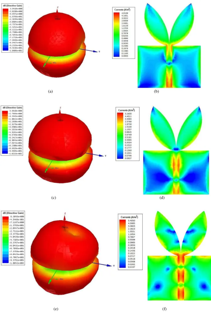
matching occurs at 3.5 GHz. Fig. 10 shows the directive gain patterns and electric current
distributions for the frequencies 3.2, 6.2 and 10.1 GHz, respectively. It can be seen by Fig. 13 that the
UWB Inga marginata leaf-shaped antenna has directive gain patterns similar to a dipole antenna. This
is due to the truncated ground plane, thus allowing the possibility of being applied to various portable
-45 -40 -35 -30 -25 -20 -15 -10 -5 0
1 2 3 4 5 6 7 8 9 10 11 12 13 14
S
11(d
B
)
Frequency (GHz)
Measured Simulation
0 2 4 6 8 10 12 14 16 18 20
1 2 3 4 5 6 7 8 9 10 11 12 13 14
VS
WR
Frequency (GHz)
distributions. Higher current densities are notice on microstrip feedline, ground plane slitted-edge and
leaf-shaped edges.
(a)
(b)
(a) (b)
(c) (d)
(e) (f)
V. CONCLUSIONS
A parametric study and experimental verification of proposed microstrip leaf-shaped PMA
bioinspired on Inga marginata leaf was presented in this paper for UWB applications. The resonant
behavior of the proposed antenna with variation of its main dimensions was analyzed. The
experimental results indicate a bandwidth higher than 10.26 GHz, superior to the required UWB band,
which accredits the proposed antenna to applications in UWB systems. Simulated radiation patterns,
impedance on Smith chart and distribution of current density for the proposed PMA were presented
and analyzed. Simulated and measured results for return loss and VSWR are in consonance. Thus,
considering the simplicity, compact structure, low cost and the consistent results, the proposed Inga
marginata leaf-shaped printed monopole antenna appears to be quite efficient and with potential for
UWB applications.
ACKNOWLEDGMENTS
The authors would like to thank CNPq, CAPES, NAMITEC and GTEMA-IFPB the support in research.
REFERENCES
[1] A. A. L. Leyestanak, “Ultra wideband rose leaf microstrip patch antenna”. Progress In Electromagnetics Research, PIER 86, 155-168, 2008.
[2] O. Haraz and A. R. Sebak, “UWB antennas for Wirelles applications”. INTEC, pp. 125-152, 2013.
[3] P. F. S. Junior, “Projeto de antenas bioinspiradas em plantas para sistemas de comunicação sem fio”. Master’s thesis, IFPB, João Pessoa, 2015.
[4] M. E. Ghavami, R. Michael and L. B. Kohno, “Ultra Wideband Signals and Systems in Communication Enginnering”. 2nd ed. (S.l.): JonhWiley& Sons Ltd, 2007.
[5] D. R. Melo, “Antenas Compactas de Microondas de Banda Larga e Banda Ultra-Larga (UWB)”. Doctoral Dissertation in Electrical Engineering, Federal University of Pará, Belém, 2011.
[6] C. A. Balanis, “Teoria de Antenas”. Vol. 2 Transl. by: J. R. Souza. Ri de Janeiro: LTC, 2009.
[7] C. L. Heringer, “Desempenho e Complexidade de Sistemas DS-UWB em Canais Multipercursos Densos”. Master’s thesis, University of Londrina, Center of Technology and Urbanism, Department of Electrical Engineering. Londrina, 2007.
[8] N. Z. Chen and M. Y. W. Chia, “Broadband Planar Antennas: Design and Applications”. Chichester: Wiley, 2006. 243 p.
[9] L. X. Bao, M. J. Ammana, “Investigation on UWB printed monopole antenna with rectangular slitted ground plane”.
Microwave Opt. Technol. Lett., v.49, p.1578-1585, Jul. 2007.
[10]O. M. H. Ahmed, A. R. Sebak, “A novel maple-leaf shaped UWB antenna with a 5.0-6.0 GHz band-notch characteristic.” Progress In Electromagnetics Research, vol. 11, 2009.
[11]Inga Marginata Wild. Disponível em: flora.ipe.org.br/sp/146?pdf=1. Acesso em: 12 Jan. 2016.
[12]T. Pickering, G. Wyatt, “Inga marginata, leaves”. Disponível em:
www.discoverlife.org/mp/20p?see=I_BC1493&res=640. Acesso em: 12 Jan. 2016.
![Fig. 1. Geometry of a rectangular printed monopole antenna [3].](https://thumb-eu.123doks.com/thumbv2/123dok_br/18888551.424420/3.892.335.591.113.338/fig-geometry-rectangular-printed-monopole-antenna.webp)