Abstract Narrow band is the major inconvenient of the
microstrip antenna. However, various multiband techniques are proposed towards several applications. A simple configuration of the rectangular microstrip antenna allows operating a system of satellite communication in two bands. The configuration consists of a single radiant element and substrate with low dielectric constant. The antenna is fed by a micro-strip line attached in the corner of the patch. This antenna covers two bands, the K and Ku bands, simultaneously. With the same parameters as simple antenna, other shapes are compared with rectangular array antenna, to improve the performances of the antenna and vary their operating frequencies. The designated configurations of the antenna arrays contain 2, 4 and 8 radiating elements.
Index terms— Rectangular microstrip antenna, antenna array, corner fed, dual-band.
I. INTRODUCTION
Recently, the modern telecommunications has been using devices covering two or more frequency
bands simultaneously. Indeed, microstrips antennas that allow to guarantee this request must have
more or less complex configurations. However, the antennas arrays offer a major interest to improve
and change the performances of the single antenna [1-4].
The conception of dual-band microstrips antennas uses various feeding techniques. However, other
configurations, such as aperture, U-shape and shorting pines are also used [1-6]. Techniques used to
increase the bandwidth are also valid to reach a functioning in dual-band [1-2]. Thus, for multilayer
configurations, the electromagnetic coupling or the coupling by crack, with adjustment of the air gap,
can be used to operate the antenna in double band [7-9]. Hybrid configurations by connecting a
circular antenna to a waveguide were conceived for a functioning in double band [8-9]. Moreover,
novel microstrip antennas are described for this type of functioning [10-12].
In this paper, the rectangular patch antenna operate in Ku and K bands, whose the intervals of
frequency, respectively, [12 -18] GHz and [18 -28] GHz. The designed configurations are formed by
Conception of Bi-band Rectangular
Microstrip Array Antenna
ZAAKRI Safa, ZENKOUAR Lahbib,
Eletronic and Communication Laboratory, EMI, Mohammed V University, Rabat-Morocco
[email protected],[email protected]
BRI Seddik
Material and Instrumentation Groups, High School of Technology, ESTM, Moulay Ismail
single patch (antenna 1), two patches (antenna 2), four patches (antenna 3) and eight patches (antenna
4).
II. ANTENNA ARRAYS CONFIGURATIONS
Many theoretical studies on antenna arrays have been published [2-5]. Linear arrays antenna is the
basic configuration, can be applied to planar arrays. Each element is an electric or magnetic current
source, which gives rise to a radiated field, the solution to Maxwell’s equations [3].
Arrays of antennas are used to direct radiated power towards a desired angular sectors. The
number, geometrical arrangement and relative amplitude and phases of the array elements depend on
the angular pattern that must be achieved. The most basic property of the array is that the relative
displacements of the antenna elements with respect to each other introduce relative phase shifts in the
radiation vectors, which can then add constructively in some directions or destructively in others [4].
By definition, the radiation vector is the three-dimensional Fourier transform of the current
density,
= . (1)
Thus, the radiation vector of the translated current will be:
= . = . = . 2
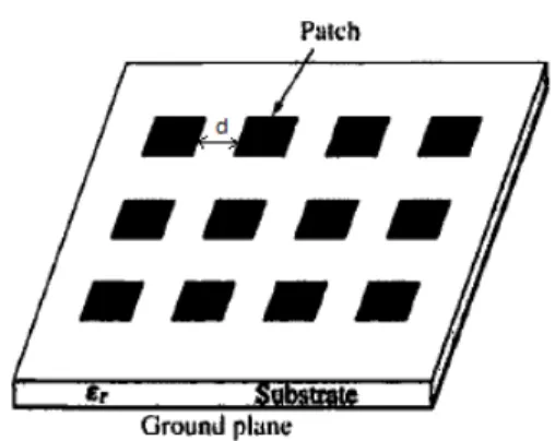
d is a distance between elements as shown in Fig. 1,
Fig. 1. Array configuration (two-dimensional array)
A single-element is usually not enough to achieve technical needs. That happens because its
performance is limited. A set of discrete element, which constitute an antenna array. The geometry
and type of element characterize an antenna array. For simplicity, implementation and fabrication
reason, the elements are chosen in such a way so as to be identical and parallel. For the same reason,
The proposed structure is simulated using Ansoft HFSS. A single layer corner fed rectangular
microstrip antenna for dual band has been developed [14]. Corner fed micro-strip array antennas are
proposed. First the dimensions of the patch and the feed line are to be determined and the feed line is
to be placed properly to resonate at Ku band only.
This paper proposes the microstrip antenna double band with the same size of the microstrip
antenna working in Ku band. The geometry of the rectangular microstrip antenna dual-band is showed
on the Fig. 2. The dimensions of the rectangular radiating element are (7.46 × 6.54) mm2. The
substrate is in Arlon DiClad 880 of dielectric constant = 2.2and thickness equal to 0.508 mm.
Fig 2. Configuration of a microstrip antenna dual-band (antenna 1)
Recently, the antennas arrays have been widely used to multiply the performances of the simple
antennas in diverse domains such as the wireless communication, where the antenna array allows
covering cellular communication coverage, also in the satellite systems [15-17]. The simple structure
of microstrip antenna, previously, was used to form three configurations of antennas with 2 patches,
with 4 patches and with 8 patches.
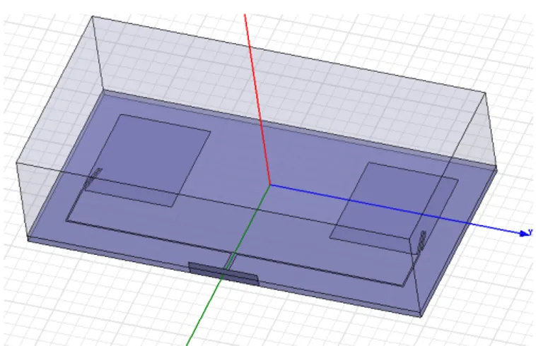
The novel configurations of microstrips antennas dual-band with 2 patches (antenna 2), 4 patches
(antenna 3) and 8 patches (antenna 4) is shown on Fig. 3 to Fig. 5.
Fig. 4. Microstrip antenna with 4 patches (antenna 3)
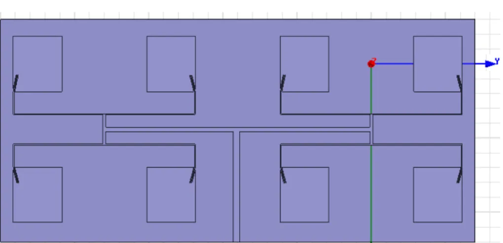
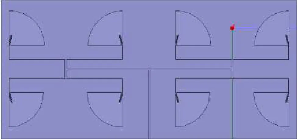
Fig. 5. Microstrip antenna with 8 patches (antenna 4)
III. RESULTS AND DISCUSSION
The feeding technique of a rectangular microstrip antenna through the corner of the patch, as
shows Fig. 6, allows a functioning in double band. So, the position and the width of the microstrip
line influence the performances of the antenna.
The line position (see Fig. 6) on the patch is indicated by dx and dy coordinates. These positions
are determined by repetitive simulation of various positions. On every position, we fix one of the
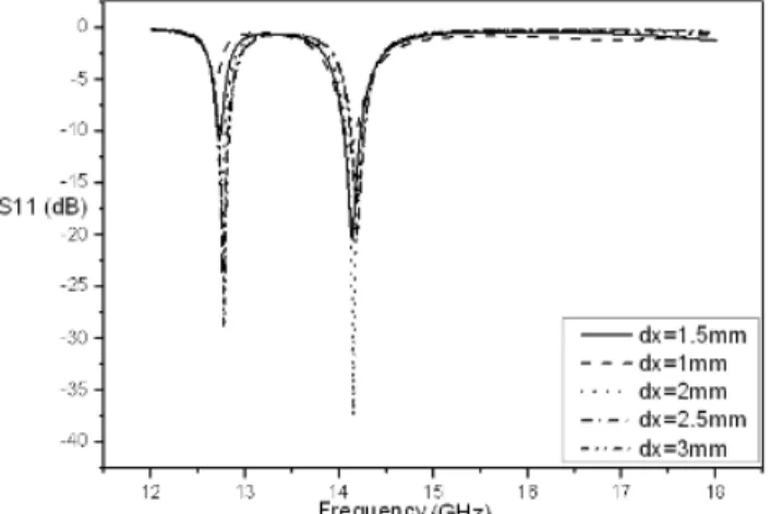
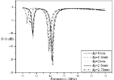
coordinates and we vary the other one. On Fig. 7 and Fig. 8, the variation of S parameter according to
the frequency by fixing dy and on the Fig. 9 and Fig. 10 the variation of S parameter according to the
Fig. 6. Feeding technique of dual-band antenna
On the K band (Fig. 7), the best position of the feed line is the position equal to dx=1.5 mm, the
return loss equal to 25 dB, compared with other positions. The results (see Fig. 8) of the positions
dx=1.5 mm and dx=2 mm are better on the Ku band. However, considering the results on the K band,
the return loss in the position dx=1.5 mm reached the minimum. Indeed, this position offers on the Ku
band two frequencies with a return loss affected up to 20 dB.
Fig. 7. Variation of S11 according to the frequency on the K band with dy=2.6 mm
Most of the energy was absorbed by the antenna in position dy=2.5 mm (Fig. 9 and Fig. 10). The
return loss is approximately equal to 35 dB. So, the orderly 2.5 mm communicates the best results
compared with the other positions and on the dual-band.
Fig. 9. Variation of S11 according to frequency on the Ku band with dx=1.52 mm
Fig. 10. Variation of S11 according to frequency on the K band with dx=1.52 mm
In conclusion, the best results on the K and Ku bands are obtained by fixing the values of dx at
1.5 mm and dy at 2.6 mm. Fig. 21 shows the radiation patterns of antenna 1. It is observed that the
radiation pattern of antenna 1 on the K band shows end-fire radiation and on the Ku band, radiation
shows the broadside radiation.
Other shapes are studied, the circular sector and triangular microstrip antennas. We change the
shape of the patch but all other parameters are the same as found in literature antennas [14]. The gain
is increased by changing the shape of the patch. Table I, II and III present a comparison between
3.1. RESULTS FOR SINGLE PATCH
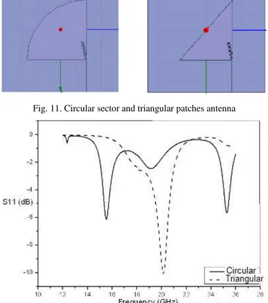
We added the circular sector and triangular antenna as shown in Fig. 11. Fig. 12. shows the
simulated return loss for triangular and circular sector microstrip antennas.
Fig. 11. Circular sector and triangular patches antenna
Fig. 12. Variation of S11 according to frequency for circular sector and triangular antenna
Table I: Result of different shape of single antenna
Triangular antenna Circular antenna
Resonance frequency (GHz) 20,13 15,52 25,29
Return loss (dB) -10,1 -6,12 -5,65
Total Gain (dB) 3 6
3.2. RESULTS FOR 1×2 ARRAY
The antenna 2 is designed from the antenna 1. The configuration of this antenna (see Fig. 3)
contains two similar patches outstripped at a distance equal to 18 mm. The result of simulation in the
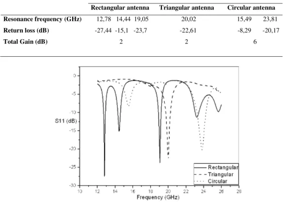
Ku and K bands and comparison between different shapes are represented on Fig. 13. The radiation
From Fig. 14 and the result shown in Table II, adding the other patch increase the bandwidth of
frequencies on both band and the circular sector micro-strip antenna improve the gain of antenna.
Thereby, it causes a change in the radiation of the antenna. On K band, the radiation pattern shows the
broadside radiation characteristic.
Fig. 13. Triangular and circular sector patches antenna
Table II. Result of different shape with two patches
Rectangular antenna Triangular antenna Circular antenna
Resonance frequency (GHz) 12,78 14,44 19,05 20,02 15,49 23,81
Return loss (dB) -27,44 -15,1 -23,7 -22,61 -8,29 -20,17
Total Gain (dB) 2 2 6
Fig. 14. Variation of S11 according to frequency for antenna 2 and comparison to circular sector and triangular antenna
3.3. RESULTS FOR 2×2 ARRAY
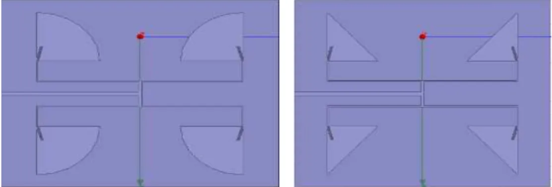
Four elements arrays (antenna 3) are fed by one port by the microstrip line. However, the position
of four similar patches is in the form of a matrix of 2×2 (see Fig. 4 and Fig. 15). The results of
software HFSS, on both bands, are presented in Fig. 16. The radiation patterns on each resonant
frequencies of the antenna 3 are shown in Fig. 23. At all resonant frequencies, the radiation patterns
Fig. 15. Circular sector and triangular patches antenna
Table III. Result of different shape with four patches
Rectangular antenna Triangular antenna Circular antenna
Resonance frequency (GHz) 12,66 20,26 24,7 12,9 18,96 20,26 25,43 12,6 16,36 19,77
Return loss (dB) -14,55 -23,45 -15,68 -10,76 -14,27 -15,81 -19,17 -9,7 -11,11 -9,48
Total Gain (dB) 5 3 10
Fig. 16. Variation of S11 according to frequency for antenna 3
and comparison to circular sector and triangular antenna
3.4. RESULTS FOR 4×2 ARRAY
The last configuration consists of 8-elements (antenna 4) of the same size. The rectangular and
circular sector microstrip array antenna with eight elements is shown inFig. 5 and Fig. 17. The result
of simulation by HFSS is shown in Fig.18 and Fig. 19. For antenna 4, the result radiation is steered
Fig. 17. Circular sector array microstrip antenna
Fig. 18. Variation of S parameter according to frequency
of circular sector microstrip antenna
Fig. 19. Variation of S parameter according to frequency of antenna 4
The frequencies of the proposed antennas are generated in the range of frequencies of the K band
from 12 GHz to 18 GHz and the Ku band from 18 GHz to 26 GHz. The variation of S parameter
according to the frequency, to the antenna 1, shows the functioning on the K and Ku bands
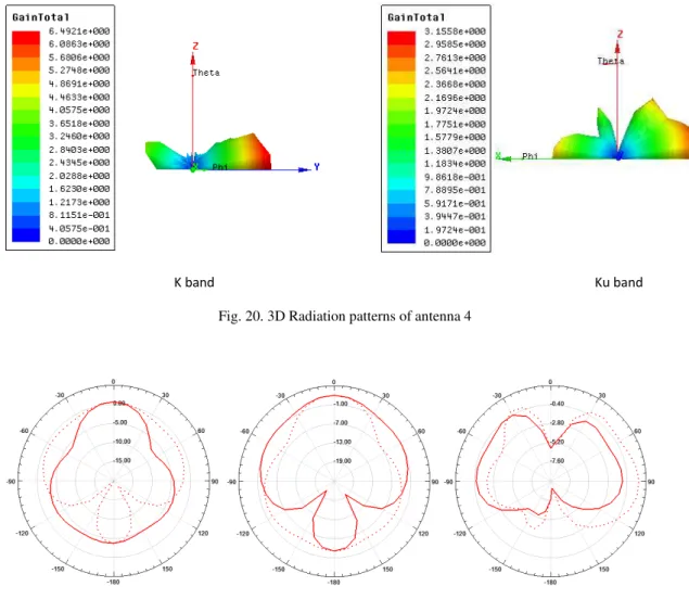
The variation of return loss shows the resonant frequencies of antenna 4. It is observed an increase
of bandwidth for all resonant frequencies and gain reaches 10dB for circular sector microstrip
antenna. Radiation patterns of all the proposed antennas are simulated using Ansoft HFSS at their
resonating frequencies. The radiation patterns in the E-plane ( is the = 0° plane) and the H-plane
( is the = 90° plane) of the rectangular microstrip antenna arrays at all resonant frequencies are
shown in Fig. 21, Fig. 22, Fig. 23 and Fig. 24. It is observed that the radiation characteristic of all
proposed antennas is improved as multi-directional radiation to unidirectional. However, from Fig. 24
the radiation patterns of all frequencies of Ku and K bands of antenna 4 are situated in one side.
Fig. 20. 3D Radiation patterns of antenna 4
Fig. 21. Radiation patterns of antenna 1 in resonance frequencies: E-plane, H-plane
K band Ku band
Fig. 22. Radiation pattern of antenna 2 in resonance frequencies: E-plane, H-plane
Fig. 23. Radiation pattern of antenna 3 in resonance frequencies : E-plane, H-plane
Fig. 24. Radiation patterns of antenna 4 in resonance frequencies: E-plane , H-plane
IV. CONCLUSION
The new configurations proposed the antennas arrays, based on the configuration of the corner fed
rectangular antenna, operate on double band. These antennas are miniature and compact, their
integration in the satellite communication systems will be easier and more important. Indeed, this
result will be taken advantage of by the satellite systems needing a functioning multi-band. Each
configuration has its own operation and its advantages over others. More can be achieved by adding
another radiating element. Another shape, triangular and circular, improves the operation of the
demonstrates the ability of microstrip antennas to adapt to all applications by varying feeding
techniques and design of radiation element.
REFERENCES
[1] K. Girish, and K. P Ray, ‘‘Broadband Microstrip Antennas’’, Artech House antennas and propagation library, 2003.
[2] C. Zhi Ning, and Y. W. C. Michael, ‘‘Broadband Planar Antennas: Design and Applications’’, Institute for Infocomm
Research, Singapore, 2006.
[3] L. Josefsson, P. Persson, ‘‘Conformal array antenna theory and design’’, IEEE Antennas and Propagation Society,
Sponsor, pp. 15-40, 2006.
[4] S. J. Orfanidis, D. Ramaccia, and A. Toscano, ‘‘Electromagnetic waves and antennas’’, Dept of Electrical and
Computer Engineering, Rutgers University, Piscataway, NJ 08854.
[5] J. R. James, and P. S. Hall, ‘‘Handbook of Microstrip Antennas ’’, IEE Electromagnetic waves serie 28, 1989.
[6] W. Ren, ‘‘Compact dual-band slot antenna for 2.4/5 GHz WLAN application,’’ Progress In Electromagnetics Research
B, vol. 8, pp. 319-327, 2008.
[7] K. S. Ruy, and A. A. Kishk., ‘‘A dual-polarized shorted microstrip patch antenna for wideband application ’’, Dept of
Electronical Engineering, the University of Mississipi, MS 38677.
[8] K. S. Vinod, and A. Zakir, ‘‘Dual band U-shap microstrip antenna for wireless communication’’, International Journal
of Engineering Science and Technology, vol. 2, pp. 1623-1628, Jun. 2010.
[9] D. M. Pozar, ‘‘A review of aperture coupled microstrip antennas: History, Operation, Development, and Applications,’’
Electrical and Computer Engineering, University of Massachusetts at Amherst, May. 1996.
[10] C. B. Smith., ‘‘Wideband Dual-Linear Polarized Microstrip Patch Antennas,’’ Texas A&M University, Dec. 2008.
[11] S. Bri, S. Zaakri, A. Nakhli, and A. mamouni, ‘‘Simulations of dual and broadband patch antenna,’’ European Journal
of Scientific Research, vol. 60, no. 2, pp. 237-249, 2011.
[12] A. A. Abdelaziz, ‘‘Bandwith enhacement of microstrip antenna,’’ Progress In Electromagnetic Research, PIER, pp.
311-317, 2006.
[13] Sahalos, and N. John,‘‘Orthogonal method for array synthesis: theory and the ORAMA computer tool’’, Book
publisher by John wiley & sons, 2006.
[14] M Wang., W. Wu, and D. G. Fang, ‘‘Uniplanar single corner-fed dual-band dual-polarization patch antenna array,’’
Progress in Electromagnetic Research letters, vol. 30, pp. 41-48, 2012.
[15] S. Goa, J. L. W. Li, and A. Sambell, ‘‘FDTD analysis of a dual frequency microstrip patch antenna,’’ Progress in
Electromagnetics Research, PIER, vol. 54, pp. 155-178, 2005.
[16] Y. S. H. Khraisat, ‘‘Design of 4 element rectangular microstrip patch antenna with high gain for 2.4GHz applications,’’
[17] G. Cakir, L. Sevgi, ‘‘Design, simulation and tests of a low cost microstrip patch antenna arrays for the wireless