Abstract— In this paper, a novel and compact ultra wideband (UWB) bandpass filter (BPF) based on fractal-shaped defected ground structure (DGS) is designed and developed. It is made of stepped impedance lines and a composite right/left handed-transmission line (CRLH-TL) constructed with capacitive gap in conductor strip and a hybrid fractal-shaped ring slot in ground plane. The capacitive gap between conductor strip and fractal shaped DGS play the major role for controlling the lower and upper passband cutoff frequencies. The prototype of proposed filter is fabricated and measured. Good agreement is found between simulated and measured results. The proposed UWB bandpass filter has good passband performance with 10 dB return-loss bandwidth of 2.2 to 10.6 GHz, insertion loss better than 1.1 dB and fractional bandwidth of 131%. Also, the proposed filter obtained a very wide upper-stopband from 11.4 GHz to beyond 20 GHz with rejection skirt better than 30 dB at both the lower and upper passband cutoff frequencies. Moreover, UWB BPF also shows the flat group delay performance with variation ≤ 0.75 ns in the entire passband. Thus the proposed filter can be a useful candidate for low profile future wireless communication systems.
Index Terms— Composite right/left handed transmission line, Defected ground structure, Hybrid fractal, Ultrawide bandpass filter.
I. INTRODUCTION
Rapid growth and interest for the development of Ultra wideband (UWB) system is seen since the
authorization by U.S. Federal Communications Commission (FCC) for unlicensed use of UWB
frequency band from 3.1GHz to 10.6 GHz for commercial purposes in 2002 [1]. UWB system
nowadays becomes most promising technologies for short range low power indoor wireless
communication. As an important component in UWB communication systems, the UWB bandpass
filter has been rapidly developed. The great potential of UWB system for developing modern
transmission system increased the demand for designing filter with low insertion-loss, higher
out-of-band rejection capability and flat group delay characteristics within the desirable out-of-band.
A Compact UWB Bandpass Filter using
Hybrid Fractal Shaped DGS
1
Babu Lal Shahu 1
Department of Electronics and Communication Engineering, Birla Institute of Technology, Mesra, Deoghar Campus, Deoghar-814142, India
Email: [email protected]
2
Neela Chattoraj, 3Srikanta Pal, 4Dileep Kumar Upadhyay
2, 3, 4 Department of Electronics and Communication Engineering, Birla Institute of
Technology, Mesra Ranchi-835215, India Emails: [email protected],
4
Different methods have been developed to achieve UWB filter response with improved
performance. Composite right/left handed transmission line (CRLH TL) technique is proposed for
designing of a wide variety of microwave circuit for different applications. An UWB filter is
implemented using an unbalanced CRLH TL based on zero degree feeding structure [2], the CRLH
TL with capacitive cross coupling is used to design UWB filter [3] with improved selectivity, low
insertion-loss and compact size. Multimode resonator (MMR) technique in the form of step
impedance resonator (SIR) is implemented in [4] for UWB application. Stub loaded MMR is
implemented in [5, 6] to improve in-band performance by increasing the number of mode within the
passband. However, the UWB filter structures usually have an important drawback of introducing
spurious responses in the stopband. So improving out-of-band performance of the UWB filter became
a research focus nowadays. Different methods have been adopted such as cascading bandpass and
band stop filter [7], by changing resonant mode of MMR [8, 9], electromagnetic band gap (EBG)
structures [10, 11], using defected ground structure (DGS) [12, 15]. Besides the planar geometries,
fractals are very good solution to improve the performance of UWB bandpass filter in terms of size
reduction and increasing the bandwidth due to their two most common properties: self similarity and
space filling. A compact size UWB BPF is reported in [16] using CRLH-TL and Koch fractal-shape
slot in ground with small variation in group delay, but its insertion-loss was poor (1.5 dB) and also
out-of-band rejection skirts were not sharp enough. To improve the passband and out-of-band
rejection performance, a modified UWB filter is reported in [17] with Koch island-shaped stepped
impedance line and CRLH-TL synthesized using capacitive gap in conductor strip and Koch fractal
shaped slot in ground plane.
In this paper, a compact UWB BPF is presented based on stepped impedance microstrip lines and a
composite right-left handed transmission line composed of capacitive gap in conductor strip and
etching hybrid fractal-shaped ring slot in ground plane. The proposed UWB BPF is able to achieve the
10dB return-loss bandwidth from 2.2 GHz to 10.6 GHz with relative bandwidth of 131%. Also the
proposed UWB BPF has deep and sharpened out-of-band rejection skirt with wide stopband
performance. The proposed UWB filter is designed and optimized using IE3D commercial full-wave
electromagnetic (EM) software simulator on RT/Duroid 5880 substrate of dielectric constant 2.2,
thickness 1.57 mm and loss tangent 0.0009. The prototype of optimized UWB BPF is fabricated and
tested for experimental verification.
II. DESIGN OF PROPOSED UWB FILTER
Based on space filling properties of fractal structure, a fractal shaped UWB BPF is designed in
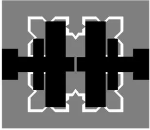
microstrip technology. The schematic of proposed UWB BPF structure is shown in Fig 1. The
proposed structure is designed using stepped impedance lines and CRLH-TL synthesized by etching
fractal-shaped ring slot in the ground plane and series capacitive gap in the conductor strip. UWB
proposed symmetric structure with series capacitive gap and a fractal-shaped ring slot (denoted by
white) in the ground plane (denoted by grey). The fractal-shaped ring slot in the ground plane is
constructed by using the first iteration of combination of Minkowski fractal and Koch fractal. The
dimensional schematic of proposed UWB filter is shown in Fig.2. For constructing the fractal shaped
ring slot initially a square shaped ring slot of size l1 x w1 mm2 is created in ground plane with slot
width of g1. Further, the square shaped ring slot is modified as Minkowski like fractal of first iteration
with arbitrary iteration factor. In the next stage, Koch fractal of first iteration order of 1/3 iteration
factor is made on the each side of Minkowski like fractal ring slot. By adjusting the size (l1 x w1) and
slot width (g1) of fractal shaped ring slot, a deep and sharpened out-of-band rejection skirt can be
obtained. Adjustment of stepped impedance line parameters (L1, L2, L3, L4, L5, L6 and W1, W2,
W3, W4) contribute to improve the pass-band and out-of-band stopband performance.
Fig. 1 Layout of proposed UWB bandpass filter
(a) Top view (b) Bottom view
III. PARAMETRIC STUDY
To obtain the best performance and final geometrical parameters the parameters of proposed UWB
BPF are optimized. Parametric study is performed by varying one parameter at a time while keeping
the other parameters constant. The parameter W1 is chosen according to 50 ohm impedance
calculated using line gauge tool of simulation software IE3D. Simulated S-parameters response with
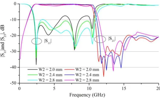
variation in parameter W2 is shown in Fig. 3. It can be seen that the best response is obtained for W2
= 2.4 mm. For values of W2 < 2.4 mm, the filter is not able to achieve the desired UWB passband
performance although the out-of-band stopband performance is good. For value of W2 > 2.4, the
insertion-loss in passband is increased with little spurious response in stopband.
Fig. 3 Simulated return-loss and insertion-loss with variation in parameter W2
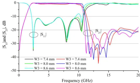
The effect of parameter W3 on return-loss and insertion- loss performance is depicted in Fig.4. Best
performance is observed for W3 = 8.0 mm. The passband insertion-loss for W3 = 7.4 mm is more and
out-of-band spurious response is also observed. For higher value of W3 i.e. for W3 = 8.6 mm, the
passband -10 dB return-loss bandwidth is decreased although deep and sharp out-of-band rejection
skirt is obtained. Similarly for parameter W4, the passband return loss and insertion-loss performance
is better for W4 = 13.4 mm as presented in Fig.5. In the passband the return-loss is increased at the
lower frequency end for W4 < 13.4 mm and at the middle of the passband for W4 > 13.4 mm. No
Fig. 4 Simulated return-loss and insertion-loss with variation in parameter W3
.Fig. 5Simulated return-loss and insertion-loss with variation in parameter W4
The parameters L1, L2, L3, L4, L5 and L6 are also optimized to improve the performance of
proposed UWB filter. Variation in S-parameters with dimensional parameters L1 is shown in Fig. 6.
The optimized value of L1 is taken equal to 2.5 mm as it gives the best performance in passband as
well as in stopband. It is observed that the passband return-loss for L1 = 3.0 mm is increased at upper
frequency arround at 9.8 GHz. For lower value of L1 i.e. at L1 = 2.0 mm, increase in return-loss is
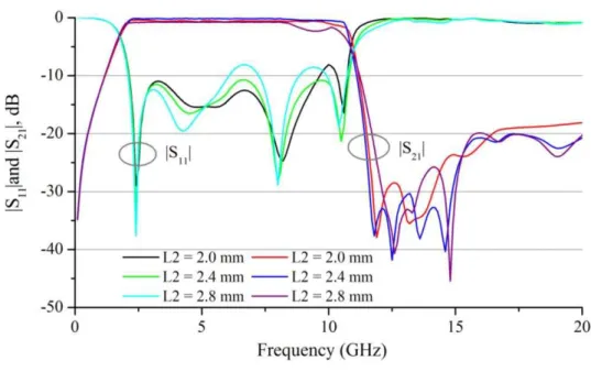
seen in the middle of passband arround at 6.5 GHz. Fig. 7 shows the effect of parameter L2 on
S-parameters. It is seen that insertion-loss and return-loss performance is better for L2 = 2.4 mm. Lower
or higher values of L2 do not fulfill the desired UWB passband performance. Increase in return-loss
Fig. 6 Simulated return-loss and insertion-loss with variation in parameter L1
Fig. 7 Simulated return-loss and insertion-loss with variation in parameter L2
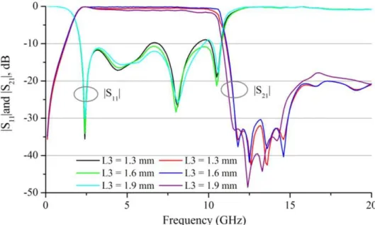
Simulated S-parameter performance with variation in parameter L3 is depicted in Fig. 8. Better
return-loss and insertion loss characteristics have been observed for L3= 1.6 mm. Insertion-loss in the
pass band become poor with increased value of L3. Also, the return-loss performance in passband is
found to be better for L3= 1.6 mm and deteriorate at higher frequency as the value of L3 decreased or
increased. In the stopband, slight variation in insertion-loss is found with good return-loss
Fig. 8 Simulated return-loss and insertion-loss with variation in parameter L3
Effect of variation of parameter L4 on S-parameter characteristics is plotted in Fig. 9. From Fig. 9,
it is seen that the higher value L4 deteriorate the S-parameter performance at higher frequency end in
the passband. The optimized dimension of L4 is chosen 0.3 mm as it provides highest -10 dB
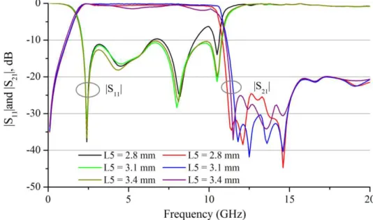
return-loss bandwidth with sharp out-of-band rejection. The Fig. 10 shows the effect of dimensional
parameter L5 on S-parameter characteristics. Better return-loss and insertion-loss response is found
for L5 = 3.1 mm. Decrease in -10 dB return-loss bandwidth is observed for lower value of L5. For
higher value of L5, insertion-loss in the passband is increased. Optimized values of different physical
parameters of proposed UWB BPF are summarized in Table I.
Fig. 10 Simulated return-loss and insertion-loss with variation in parameter L5
TABLE I. OPTIMIZED PHYSICAL PARAMETERS OF UWB BPF SHOWN IN FIG.2
Parameter W1 W2 W3 W4 L1 L2 L3 L4 L5 L6 g L W g1 l1 w1
Dimension (mm) 4.8 2.4 8.0 13.4 2.5 2.4 1.6 0.3 3.1 1.4 0.4 23 20 0.5 15 15
Fig. 11 displays the simulated surface current distributions of proposed UWB bandpass filter at
three different frequencies 3.1 GHz, 5.5 GHz and 10.5 GHz. It is observed that at 3.1 GHz the current
density is mainly concentrated in the ground plane around the fractal-shaped ring slot. At 5.5 GHz the
current is concentrated at the top plane in stepped impedance line as well as in ground plane. However
at 10.5 GHz, more concentration of current is observed in the stepped impedance microstrip line
section with little concentration around the ring slot in the ground plane.
IV. MEASUREMENT RESULTS AND DISCUSSION
To validate the performance, a prototype of proposed UWB BPF is fabricated based on optimized
dimensional parameters and measured. The photograpgs of top and bottom of fabricated prototype is
represented in Fig.12 (a) and (b) respectively. To validate the simulation results the performance
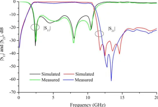
parameters of UWB filter are measured and compared with simulated results. The comparison
between simulated and measured return-loss and insertion-loss performance is plotted in Fig.13, and
are found to be in good agreement with each other. It can be seen that the measured insertion-loss,
|S21| is better than 1.1 dB within the entire -10 dB return loss passband from 2.2 GHz to 10.6 GHz
irrespective of simulated |S21| which is better than 0.6 dB.
(a) Top view
(b) Bottom view
Fig. 12 Fabricated photograph of proposed UWB BPF
Beyond UWB frequency band, deep and sharp skirt is observed with rejection level better than 37
dB at both lower and upper stopband transition. Also, very wide upper-stopband is obtained from
11.4 GHz to beyond 20 GHz. The measured return-loss in upper-stopband is almost flat and agreed
with simulated response with performance better than 0.8 dB extended up to above 20 GHz. Also the
measured and simulated insertion- loss in this frequency band of interest is found to be better than 20
upper-stopband characteristic. The little discrepancy in simulated and measured results may be due to
fabrication tolerances and improper soldering of SMA connector.
The group delay performance for proposed hybrid fractal shaped UWB bandpass filter is plotted
in Fig. 14 showing a good agreement between simulated and measured result. It is observed that the
measured group delay varies between 1.20 to 1.95 ns within the desired UWB frequency band while
the simulated group delay varies between 1.40 to 1.85 ns. Thus the designed filter is able to achieve
maximum group delay variation of 0.75 ns which shows a good phase linearity and better
performance in time domain.
Fig. 13 Comparison of simulated and measured S-parameters
V. CONCLUSION
A compact and novel ultra wideband bandpass filter based on CRLH-TL and hybrid fractal-shaped
defected ground structure is designed, fabricated and measured. Effects of various design parameters
have been studied to improve the performance of filter and verified experimentally. The measurement
results are found in good agreement with the simulated results. The proposed UWB BPF is compact in
size (23 x 20 mm2) with measured return-loss and insertion-loss performance better than 10.5 dB and
1.1 dB respectively throughout the passband. Moreover, the filter is also able to achieve deep and
sharpened out-of-band rejection level better than 37 dB with wide upper-stopband performance.
Therefore the proposed geometry of UWB BPF can be a good candidate for modern small size
wireless communication systems.
REFERENCES
[1] Revision of Part 15 of the commission's rules regarding ultra- wideband transmission system,"ET-Docket 98-153,
First note and order, Federal Communication Commission,” Feb 2002.
[2] Chou, T.-C., M.-H. Tsai, and C.-Y. Chen, “A low insertion loss and high selectivity UWB bandpass filter using
composite right/left-handed material," Progress In Electromag. Research C, vol. 17, pp. 163-172, 2010.
[3] Huang, J.-Q. and Q.-X. Chu, “Compact UWB band-pass filter utilizing modified composite right/left-handed
structure with cross coupling," Progress In Electromag. Research, vol. 107, pp. 179-186, 2010.
[4] Zhu, L., S. Sun, and W. Menzel, “Ultra-wideband (UWB) bandpass filter using multiple-mode resonator," IEEE
Microw. Wireless Comp. Lett., vol. 15, no. 11, pp. 796-798, Nov 2005.
[5] Li, R. and L. Zhu, “Compact UWB bandpass filters using stub-loaded multiple-mode resonator," IEEE Microw.
Wireless Comp. Lett., vol. 17, no. 1, pp. 40-42, Jan 2007.
[6] Chu, Q.-X. and X.-K. Tian, “Design of UWB bandpass filter using stepped-impedance stub-loaded resonator," IEEE
Microw. Wireless Compon. Lett., vol. 20, no. 9, pp. 501-503, Sep 2010.
[7] Tang, C.-W. and M.-G. Chen, “A microstrip ultra-wideband bandpass filter with cascaded broadband bandpass and
bandstop filters," IEEE Trans. Microw. Theory Tech., vol. 55, no. 11, pp. 2412- 2418, Nov 2007.
[8] Wong, S.-W. and L. Zhu, “Quadruple-mode UWB bandpass filter with improved out-of-band rejection," IEEE
Microw. Wireless Compon. Lett., vol. 19, no. 3, pp. 152-154, Mar 2009.
[9] Deng, H.-W., Y.-J. Zhao, X.-S. Zhang, L. Zhang, and S.-P. Gao, “Compact quintuple-mode UWB bandpass filter
with good out- of-band rejection," Progress In Electromag. Research Lett., vol. 14, pp. 111-117, 2010.
[10] Garcia-Garcia, J., J. Bonache, and F. Martin, “Application of electromagnetic bandgaps to the design of ultra-wide
bandpass filters with good out-of-band performance," IEEE Trans. Microw. Theory Tech., vol. 54, no. 12, pp.
4136-4140, Dec 2006.
[11] Wong, S.-W. and L. Zhu, “EBG-embedded multiple-mode resonator for UWB bandpass filter with improved
upper-stopband performance," IEEE Microw. Wireless Compon. Lett., vol. 17, no. 6, pp. 421-423, Jun 2007.
[12] Fallahzadeh, S. and M. Tayarani, “A new microstrip UWB bandpass filter using defected microstrip structures,"
Journal of Electromag. Waves and Applications, vol. 24, no. 7, pp. 893-902, 2010.
[13] I-Tseng Tang, Ding-Bing Lin, Chi-Min Li, and Min-Yuan Chiu, “Ultra-wideband bandpass filter using hybrid microstrip-defected-ground structure,” Microw. and Optical Tech. Lett.,vol.50, No.12, Dec 2008
[14] B. Xia1, L.-S. Wu, and J. F. Mao, “An ultra-wideband balanced bandpass filter based on defected ground structures,”
[15] Lee, J.-K. and Y.-S. Kim, “Ultra-wideband bandpass filter with improved upper stopband performance using
defected ground structure," IEEE Microw. Wireless Compon. Lett., vol. 20, no. 6, 316-318, Jun 2010.
[16] Jian An, Guang-Ming Wang, Wei-Dong Zeng, and Lai-Xuan Ma, “Composite right/left-handed transmission line based on koch fractal shape slot in the ground and UWB filter application”, Microw. and Optical Tech. Lett., vol. 51, no. 9, Sep 2009.