Comparison of Non-Axisymmetric Dynamic
Response of Imperfectly Bonded Buried
Orthotropic Thick and Thin Fluid filled
Cylindrical Shell due to Incident Shear Wave
(SH Wave)
Rakesh Singh Rajput*, Dr Sunil Kumar, Dr Alok Chaube
Reader Mechanical Engineering
Directorate of Technical Education Bhopal (M.P.) India e-mail [email protected]
J. P. Dwivedi
Dept. of Mechanical Engineering IT-BHU
Varanasi, India ABSTRACT
This paper deals with the effect of fluid presence on the non-axisymmetric dynamic response of imperfectly bonded buried orthotropic thick and thin fluid filled pipeline due to incident horizontal shear wave. In the thin shell theory the effect of shear deformation and rotary inertia is not considered. The pipeline has been modeled as an infinite cylindrical shell imperfectly bonded to surrounding. An approach similar to Dwivedi and Upadhyay (1989) has been followed wherein a thin layer is assumed between the shell and the surrounding medium (soil) such that this layer possesses the properties of stiffness and damping both. The degree of imperfection of the bond is varied by changing the stiffness and the damping parameters of this layer. Although a general formulation including P-, SV- and SH-wave excitations has been presented, numerical results are given for the case of incident SH-SH-waves only. When it is excited by seismic-wave there are two types of soil movements that take place at the time of earthquake both around the epicenter. One is vertical movement (up and down) of the soil and due to this movement the shear wave (S-V and S-H) is developed on the surface of the pipe and other is horizontal movement (compressive or extend) of the soil due to this the longitudinal wave or pressure wave or P-wave is developed on the surface of the pipe. Since it is not possible to condense the results for P-, SV- and SH-waves into one paper, in this paper the results concerning only the shear waves (SH Wave) are to be presented..With increasing urban population and its dependence on utility services, dynamic response of pipelines to seismic excitation has become a subject of importance
Key words: - Thick and thin shell Shear wave, Orthotropic, Imperfect bond, Seismic Wave, Non-Axisymmetric, Dynamic Response, Buried Pipelines, Thick and Thin Shell, and shear Wave.
INTRODUCTION
After arrival of reinforced plastic mortar (RPM) pipes need was felt to analyze the pipe of orthotropic materials. As a result, during past few years a number of papers Cole Ritter and Jordon (1979); and Singh, Upadhyay, and Kishore (1987) have appeared on the axisymmetric dynamic response of buried orthotropic pipe/shells. Later Chonan (1981); Dwivedi and Upadhyay (1989; 1990; 1991); and Dwivedi, Singh and Upadhyay (1991) have analyzed the axisymmetric problems of imperfectly bonded shell for the pipes made of orthotropic materials. Upadhyay and Mishra (1988) have presented a good account of work on non-axisymmetric response of buried thick orthotropic pipelines under seismic excitation. Again Dwivedi, Mishra, and Upadhyay (1992a; 1992b); Dwivedi, Singh, and Upadhyay (1993a; 1993b; 1996); and Dwivedi, Mishra, and Upadhyay (1998) have analyzed the non-axisymmetric problem of imperfectly bonded buried thick orthotropic cylindrical shells. There is no work is available discussing the effect of bond imperfection on the non axisymmetric response of buried thin pipes made of orthotropic materials Kouretzis et. al (2007 ) have presented analytical calculation of blast-induced strains on buried pipe lines
Hasheminajad and Kazemirad(2008) Dynamic response of an eccentrically lined circular tunnel in poroelastic soil under seismic excitation.
Lee, et al. (2009) in their paper has done the risk analysis of buried pipelines using probabilistic method. But in all these analyses pipeline has been modeled as thick shell. As far as the non-axisymmetric dynamic response of thin shell is concerned no work has been reported so far. Therefore, in this paper we have attempted to analyze the effect of imperfect bond on the non- axisymmetric dynamic response of buried orthotropic thin pipelines.
BASIC EQUATIONS & FORMULATIONS
The pipeline has been modeled as an infinitely long thin cylindrical shell of mean radius R and thickness h. It is considered to be buried in a linearly elastic, homogeneous and isotropic medium of infinite extent. Basic approach of the formulation is to obtain the mid plane displacements of the shell by solving the equations of motion of the orthotropic shell. Traction terms in the equations of motion are obtained by solving the three-dimensional wave equation in the surrounding medium. Appropriate boundary conditions are applied at the shell surfaces. Equations arising out of boundary conditions along with the equations of motion of the shell are simplified to yield a response equation in matrix form.
Equation governing the non axis-symmetric motion of an infinitely long orthotropic cylinder has been derived following the approach of Mirsky and Herrmann [1], Displacement at a particular point in the shell is taken in the form
Consider an infinitely long thick cylindrical shell of mean radius R and thickness h buried in a linearly elastic, homogeneous and isotropic medium of infinite medium. A thin layer is assumed between the shell and the surrounding medium (soil). The degree of imperfection of the bond is varied by changing the stiffness and the damping parameters of this layer. The shell is excited by a shear wave (SH-wave). A wavelength
(=2Π/) is considered to strike the shell at an angle Φ with the axis of the shell. Let a cylindrical polar co-ordinate system (r, , x) is defined such that x coincides with the axis of the shell and, in addition, z is measured normal to the shell middle surface, which is given ash/2
z
h/2
,
R
r
z
(1)The basic equations which describe the dynamic behavior of thick cylindrical shells with bending resistance under arbitrary loads are derived from the system of equations which has been presented by P.C. Upadhyay and B.K. Mishra [2]
;
t
w
h
P
R
N
x
Q
Q
R
1
2 2 *
1 x
(a)
];
)
12
/
(
[
1
2 2 2
2 2 *
2
t
R
h
t
v
h
P
R
Q
x
N
N
R
x
(b)]
)
/
[(
1
2 2 2 2 3
t
I
t
v
R
I
P
Q
x
M
M
R
x
(c)];
)
12
(
[
1
1
2 2 2
2 *
4
t
R
h
t
u
h
P
N
R
x
N
R
x x
xx
]
)
/
[(
1
2 2 2 2 5t
I
t
u
R
I
P
Q
x
M
M
R
M
x x x x x xx
(e)But in the thin shell theory effect of shear deformation and rotary inertia is not considered. After equating all the inertial and moments term equal to zero the equilibrium equations of thick shell in stress form (from above reference) reduces to
;
t
w
h
P
R
N
x
Q
Q
R
1
2 2 * 1 x
(a);
t
v
h
P
R
Q
x
N
N
R
1
2 2 * 2 x
(b);
0
Q
x
M
M
R
1
x
(c)];
[
1
1
2 2 * 4t
u
h
P
N
R
x
N
R
x xx
(d)0
1
x x xxx
M
Q
R
M
(e) (2)In connection with the equation of equilibrium it can be argued that transverse shearing force
Q
makes a negligible contribution to equilibrium of forces in circumferential direction. So after makingQ
equal to zero in Eq. 2(b) find out the value ofQ
andQx
from Eq. 2(c) and 2(e) and put into Eq. 2(b) and 2(d), above equations reduces to;
t
w
h
P
R
N
M
R
1
x
R
M
x
R
M
x
M
2 2 * 1 2 2 2 x 2 x 2 2 xx 2
(a);
t
v
h
P
x
N
N
R
1
2 2 * 2 x
(b)};
t
u
{
h
P
N
R
1
x
N
2 2 * 4 x xx
(c) (3)
;
t
w
h
P
R
N
M
R
1
x
R
M
x
R
M
x
M
2 2 * 1 2 2 2 x 2 x 2 2 xx 2
(a);
t
v
h
P
x
N
N
R
1
2 2 * 2 x
(b)};
t
u
{
h
P
N
R
1
x
N
2 2 * 4 x xx
(c) (4)
For thin shell theory shear deformation is not considered due to negligible thickness. So the shear strain components according to Herrman and Mirsky [1] about z-axis in r- and r-x plane
xz
and
z
will be zero (no coupling is there due to negligible thickness) but at the same time shear stress component would be there due to Kirchhoff’shypothesis. So according to Herrman and Mirsky [1]
0
;
x
w
x xz
0
)
z
v
(
z
R
1
w
z
R
1
z
So from the above equations
);
w
v
(
R
1
;
x
w
x
Here
x
and
are angle of rotation in r-x and r- plane but in the r- plane the tangential deflection is negligible compared to component of radial deflection in that direction. So
);
w
(
R
1
;
x
w
x
(5)From the above, stress resultants come out to be
);
v
w
(
R
E
x
w
R
D
x
u
E
N
2 x p2 p
xx
];
x
w
)
R
/
I
(
u
)
R
/
I
h
(
R
1
x
v
h
[
G
N
2 2 2 xx
);
w
R
x
w
R
x
u
[
R
D
M
2 2 x 2 2 xx
];
u
)
R
/
I
(
x
w
)
R
/
I
(
2
[
G
M
2 2 xx
];
u
)
R
/
h
(
x
w
)
R
/
I
(
x
v
h
[
G
N
2 2 xx
;
x
u
E
w
R
D
)
v
w
(
)
R
D
R
E
(
N
x p2 2 3 ' 3 ' ' p
];
x
w
2
x
v
[
)
R
/
I
(
G
M
2 xx
;
x
w
D
)
v
w
(
R
D
w
R
D
M
2 2 x 2 ' 2 2 2 '
(6)
When we put these values of stress resultants into above equation of equilibrium, we get the required equation of motion of shell in the matrix form as
[{L} {U}] + {P*} = 0 (7)
Where [L] is a matrix 5x5 for thick shell and 3x3 for thin shell operator with terms
;
t
h
R
D
R
E
x
R
I
G
4
x
R
D
2
R
D
R
D
x
D
L
2 2 4 ' 2 ' p 2 2 4 2 x 2 2 2 2 x 4 4 4 ' 2 2 4 ' 4 4 11
;
R
D
R
E
x
R
I
G
R
D
L
4 ' 2 ' p 2 2 4 2 x 3 3 4 '12
;
x
R
I
G
x
R
E
x
R
D
L
2 3 3 x p x 3 3 13
;
L
L
21
12
;
x
R
E
x
R
h
G
L
2 p x 2
x
23
L
31
L
13;
L
32
L
23;
;
R
I
h
R
G
x
E
L
2 2 2 2
x 2
2 p 33
And{U} = [w v
u
x ]T for thick shell and {U} = [w v u ]T for thin shellDisplacement components of the middle surface of the shell in the radial, tangential and axial directions respectively, the elements of {P*} are given by Herrman and Mirsky [1] as:
,
R
z
1
P
,
R
z
1
P
h/2
h/2 -z *
2 2 / h _h/2 zz *
1
,
R
z
1
P
,
R
z
1
z
P
h/2
h/2 -zx *
4 2
/ h
2 / h z *
3
2 / h
2 / h zx *
5
R
z
1
z
P
Where ij denotes the stresses with their usual meaning, but for thin shell
* 3
P
andP
5* are zero. Different constants appearing in the expressions for Lij are defined as:, 12 h E D' , 12 h E D , 1
h E E
, 1
h E E
2 ' p 2
p x
x '
p x
x x
p
I=h3/12, where Ex, E are elastic moduli, x, x the Poisson ratio Gx, Gxz and Gz the shear moduli and is the density of the shell material.
'n' indicate the mode in circumferential direction; n = 0 represents the axisymmetric mode.
For the evaluation of {P*}, ij at z = (h/2) must be determined in the terms of incident and scattered field in the surrounding ground. The total displacement field in the ground is written as
d=d(i) + d(s)
i
(
x
ct
)
exp
n
cos
B
R
r
I
r
R
n
B
R
r
I
1
B
R
r
I
d
5 n 3 ' n 1 1 ' n ) i (r
i
(
x
ct
)
exp
n
sin
B
R
r
I
B
)
R
r
(
I
r
R
in
B
R
r
I
r
Rr
n
d
5 ' n 3 n 1 1 n ) i (
and
i
(
x
ct
)
exp
n
cos
x
B
R
r
I
B
R
r
I
i
d
x(i)
1 n 1 2 n 3
(8)Where B1 =
' 1
B
/R, B3 =' 3
B
/R2 and B5 =' 5
B
/R. ( ‘ ) denotes differentiation with respect to the argument of the Bessel functions. The constants B1, B3 and B5 depend on the parameters of the incident wave and may be expressed as:
n 35 2 2 n 3 1 1 1 n 1
A
)
1
(
B
,
A
i
)
1
(
B
,
A
i
)
1
(
B
(9)B cosn exp
i (x ct)
R r K r R n B R r K i B R r K
d 4 n 6
' n 1 2 ' n ) s (
r
i (x ct)
exp n sin B R r K B R r K r R in B R r K r R n d 6 ' n 4 n 1 2 n ) s (
i (x ct)
exp n cos B R r K B R r K i
d n 4
2 2 n 1 ) s (
x
(10)
Here
B
2
B
'
2
/
R
,
B
4
B
'
4
/
R
2
and
B
6
B
6
'
/
R
.
i (x ct)
exp n cos B R r I r R R r I r R n 2 B R r I i 2 B R r I 2 R r I 2 R 5 n ' n 3 " n 2 1 1 " n 2 n 2 2 2 1 ) i (rr
i
(
x
ct
)
exp
n
sin
B
R
r
I
r
nR
R
r
I
r
R
R
r
I
B
R
r
I
r
R
R
r
I
r
R
in
2
B
R
r
I
R
r
I
r
R
r
R
n
2
R
5 n 2 ' n " n 2 3 n ' n 1 1 ' n n ) i (r
i
(
x
ct
)
exp
n
cos
B
R
r
I
r
R
in
R
r
I
2
B
R
r
I
i
2
R
5 n 1 ' n 2 2 2 1 1 ' n 1 ) i (rx
i
(
x
ct
)
exp
n
cos
B
R
r
K
r
R
R
r
K
r
R
n
2
B
R
r
K
i
2
B
R
r
K
2
R
r
K
2
R
6 n ' n 4 " n 2 1 2 " n 2 n 2 2 2 1 ) s (r
i (x ct)
exp n sin B R r K r nR R r K r R R r K B R r K r R R r K r R in 2 B R r K R r K r R r R n 2 R 6 n 2 ' n " n 2 4 n ' n 1 2 ' n n ) s (r
i
(
x
ct
)
exp
n
cos
B
R
r
K
r
R
in
B
R
r
K
2
B
R
r
K
i
2
R
6 n 1 4 ' n 2 2 2 1 2 ' n 1 ) s (rx
(11)With the help of above equations the stresses at the outer surface of the shell (z = h/2 or r = R + h/2) can be obtained. Thus {P*} in Eq. (2) can be determined.
Linear Acoustic Equation for the fluid: For any disturbance propagating in the fluid governing equations are the continuity equation and the Euler equation of motion these are given as follows: displacement d(r, , x, t) at any point, satisfied the equation of motion :
(
d
)
t
d
c
d
.
c
2 2 2 2 2 1
. (12)Where,
2 / 1 m 2 2 / 1 m
1
and
c
2
c
are respectively the speeds of dilatational andshear waves in the infinite medium and are the Lame’s constant, and m is the density of the medium.
Now the mid plane displacement and slopes are assumed to be of the form;
w
w
0
cosn exp[i(x-ct)]
v
v
0
sinn exp[i(x-ct)]
u
u
0
cosnexp[i(x-ct)] (13) Plugging Eq. (13) in Eq. (2) along with the expression for {P*}, a set of three simultaneous algebraic equations are obtained for thin shell and for five simultaneous algebraic equation are obtained for thick shell..Three more equations are obtained by imposing the boundary conditions at the inner and outer surfaces of the shell: i.e., 2 / h R r ) s ( r ) i (
r
d
)
d
(
2 / h R r ) s ( ) i (
)
d
d
(
)
2
/
h
(
v
2 / h R r ) s ( x ) i ( x
x
(
d
d
)
)
2
/
h
(
u
(14) Boundary conditions at the outer surface of the shell (r = R +h/2) are obtained by assuming that the shell and the continuum are joined together by a bond which is thin, elastic and inertia less. This implies that the stress at the shell-soil interface is continuous. To take the elasticity of the bond into account, the stresses in the bond are assumed proportional to relative displacements between the shell and continuum. The inner surface of the shell continuity of the radial displacement has been assumed, i.e.,
.
2 /
h R r f r
t
d
t
w
2 / 2
/
[(
)(
(
)
]
)
(
rx r R h x x xi xsu
r
R
x r R ht
Z
S
(
rr)
r R h/2[(
r r)(
ri rsw
)]
r R h/2t
Z
S
2 / 2
/
[(
)(
(
)
]
)
(
r r R h i su
r
R
r R ht
Z
S
(15)
,
.
R
S
r R
,
.
R
S
and
S
.
R
,
x x
are the non dimensionalized stiffness coefficient of the bond in radial , tangential and axial direction respectively,
1
c
Z
rr
1
c
Z
and
1
c
Z
xx
are the non dimensionalized damping coefficient of the bond in radial , tangential and axial direction respectively,
Thus a total of eight algebraic equations are obtained for thick shell and six equations are obtained for thin shell. These eight / six equations when simplified give the final response equation, which may be put into the form
35 2 3 1 1
0
}
B
F
B
F
B
F
U
}{
Q
{
(16)Where [Q] is a (6x6)) matrix and {F1}, {F2} and {F3} are (61) matrices. But for the response of horizontal shear wave the amplitudes due to shear waves
B
1 andB
3 would be zero so the effect of {F2} and {F1} matrices would be eliminated. Putting values ofB
1=B
3= 0 and substituting values ofB
5 from Eq. (8) Eq. (13) becomes as
3 3 0}
(
1
)
F
}{
{
A
U
Q
n; N h ] Nn 2 N n 2 N N n 4 N n [ 12 h Q 2 2 1 2 1 2 x 1 2 1 4 1 3 2 1 2 1 4 2 3 11 ; Nn h ] Nn n N n [ 12 h Q 2 1 1 3 2 1 1 3 2 3 12 ; Nn h i ] N n [ 12 h i Q 2 1 x 3 1 1 3 2 2 3 13
2
K
2
K
;
2
h
1
Q
14
12
22 n
1
2 n
1
2
i
K
;
2
h
1
Q
15
1
2 n
2
;
2
h
1
K
K
n
2
2
h
1
Q
2 2 n 2 n 2 16
Q
21
Q
12;
2 3 2 1 1 2 2 1 2 2 3
22
[
n
N
]
h
]
N
n
[
12
h
Q
];
Nn
2
n
[
h
i
Q
3 1 x 12
23
K
;
2
h
1
n
K
K
2
h
1
n
2
2
h
1
Q
2 n 22 2 n 2 2 n 2 26
31 13 32 23 23 2 2
33 1 3
2
;
;
1 h
[
(
)]
;
12
Q
Q
Q
Q
h
Q
N
n n
2
i
K
;
2
h
1
Q
34
1
n
1
2
K
;
2
h
1
Q
35
12
22
n
2
;
2
h
1
K
n
i
2
h
1
Q
36 1 n 2
Q41 = 1, Q42 = Q43 = 0,
Q
44
K
n
1,
Q
45
i
1
K
n
2,
0
1
Q
;
2
h
1
K
n
Q
46 n 1 51
, Q52 = Q53 = 1;
;
2
h
1
K
n
Q
54 n 1
;
2
h
1
K
n
i
Q
55 1 n 2
Q
56
K
n
2;
Q57 = Q47, ; Q58 = Q48 ; Q59 = 0 ; Q61 =Q62 = Q63 = 0 ;
;
Q
K
;
K
i
Q
64
1 n
1 65
2 n
2 And Q66 = 0 ;
2
2
;
2
1
1 2 1 2 2 2 1 31
I
n
I
n
h
F
; 2 1 2 21 1 12 1
3 2 h I I n h
F n n
2
;2
1 1 1
3
3 i In
h
F
; 2 1, 3 1
5 1 3 4 h I n F I F n n
)]
(
2
)
(
){
2
[
)
(
{
1 " 2 1 2 2 2 1 1 1 ' 36
n nr r
r r
n
I
I
i
I
F
]
)
2
/
1
/(
)}
(
)
(
{
2
[
]
2
/
1
/(
)
(
{
1 1 ' 1 21 1
3
7
n
I
I
h
i
h
nI
F
n n
n
Other Q and F elements same as Ref [2]
2 4 6
;3 3 3 6 3 4 3 2 3 0 3 0 3 0 T X T x B B B U V W A A A B A B A B A u A v A w
U
For thick shell
2 4 6
;3 6 3 4 3 2 3 0 3 0 3 0 T T B B B U V W A B A B A B A u A v A w
U
For thin shell
Where x x 3 x xz 2 x 1
E
G
,
E
G
,
E
E
,
R
h
h
,
G
,
1
1
N
,
E
G
z x x x x z 4
,
2
h
1
,
,
h
m 12 2 2
And.
2
h
1
2
I
n
i,
I
n
i,
K
n
iand
K
n
i Can be expressed as
n
I
I
,
I
n i n 1 ii i
,
n
n 1
ii i
n 2 i 2
i 2
i "
n
I
1
-I
n
-n
1
I
,
n
i n 1
ii i
'
n
K
-
K
n
K
,
n 1
i ii n 2
i 2
i 2
i "
n
K
1
K
n
-n
1
K
.Here it must be pointed out that for an incident shear wave (SV- or SH- wave) 2 =. In the present work the non-dimensional wave number of the incident wave, i.e. (= 2 R/) has been given as input, so either 1 or 2 is always known. The other i can be obtained by using the following relations:
m
m 2
2 2 1 2
1 2
2 -1
-1 2 c c
(14)
Where m is the Poisson ratio of the medium.
RESULT & DISCUSSIONS
Results are presented for a transversely isotropic shell with r-
as the plane of isotropy. ConsequentlyE
E
z,
xxz
G
G
,
x
xz,
z
z,G
z
E
/
2
(
1
z)
. Thus we have
3
2, and)
1
(
2
/
E
/
G
z x 1 z4
. In addition
z
x
0
.
3
has been taken in the numericalcalculations. Different values of
1 and
2 used are as follows
1= 0.5, 0.1, 0.05 and
2= 0.1, 0.05, 0.02.
has been varied between 0.1 to 10.0 to take into account different soil conditions around the pipe,
= 0.01for soft soil ,
= 0.1 corresponds to the medium hard soil whereas
= 10.0 represents hard and rocky surroundings. For all the values of
,
m= 0.25 has been assumed. Thickness to radius ratio of the shell (h
) has been taken as 0.01 and the density ratio of the surrounding medium to the shell (
) has been taken as 0.75. Non-dimensional amplitude of the middle surface of the shell in the radial and axial directions (W
andU
) have been plotted against the non-dimensional wave number of the incident SH-wave (=2R/). The shell response has been shown in flexural mode (n = 1) taking stiffness coefficient (
x
r ), damping coefficient ( x r ) as bond parameter and
1 ,
2 as the shell orthotropic parameters.The bond parameters have been varied between zero and infinity.
x =
=
r=x== r= 0 corresponds to perfect bonding between the shell and surround shell.CONCLUSION
Based on the results presented following general conclusions could be drawn-.
Unlike the behavior observed in the thick and thin shell a loose contact between the shell and the surrounding soil does not always give more shell displacement as compared to those for a perfectly bonded shell. Therefore assuming a perfect bond may not always lead to a safe and conservative estimate of displacements.
Effects of bond parameters depend upon the soil conditions and the incidence angle and wavelength of the incident wave. In hard and rocky surroundings bond imperfections show more prominent effects on the shell response.
The thick shell response assumes considerable importance in soft soil condition and at higher apparent wave speed.
Thick shell response due to incident shear horizontal wave is significant only at large angle of incidence.
For large angle of incidence radial deflection is higher in thick shell at larger wavelength but at this value it is the axial deflection in thin shell, which is higher. Thus for larger wavelength thin shell is more important because the most common cause of pipeline failure is excessive axial deformation, while at smaller wavelength the thick has much importance for axial displacement.
Both the shell orthotropic parameters influence the radial displacement equally well but
2 has a stronger influence on the axial displacement than
1. On the basis of result presented it may be concluded that the response obtained under SH-wave excitation in soft and sandy soil and medium hard soil is different in nature from that due to SV-Wave excitation REFERENCES
[1] Herrman, G and Mirsky, J; "Non axially Symmetric Motion of Cylindrical Shell"; Journal of the acoustical society of America, Vol 29(10), 1957, pp. 1116-1123.
[2] P.C. Upadhyay and B.K. Mishra "Non Axisymmetric Dynamic Response of buried Orthotropic shells", J, of Sound and vibration, 121, pp 149 -160, 1988.
[3] Chonan, S. "Response of a pre-stressed, orthotropic thick cylindrical shell subjected to pressure pulses" journal of sound and vibration, Vol. 78, 1981, pp 257-267
[4] Ariman, T., & Muleski, G. E. (1981). Review of the Response of Buried Pipelines under Seismic Excitation. International Journal of Earthquake Engineering and Structural Dynamics, 9, 133-151.
[5] Muleski, G. E., Ariman, T. S., & Ariman, C. P. (1979). A Shell Model of a Buried Pipe in a Seismic environment. ASME Journal of Pressure Vessel Technology, 101, 44-50.
[6] Cole Ritter, B. W. & Jordon, S. (1979). Structural Analysis of Buried Reinforced Plastic Mortar. In: Ariman,T.,Liu, S. C., and Nickell, R. E. (Eds.), Life Earthquake Engineering Buried Pipelines, Seismic Risk and Instrumentation (pp. 114-131). New York: ASME.
[7] . Singh, V. P., Upadhyay, P. C., & Kishore, B. (1987). On the dynamic response of Buried Orthotropic Cylindrical Shells. Journal of Sound and Vibration, 113, 101-115.
[8] Dwivedi, J. P. & Upadhyay, P. C. (1989). Effect of Imperfect Bonding on the Axisymmetric Dynamic Response of Buried Orthotropic Cylindrical Shells. Journal of Sound and Vibration, 135, 477-486.
[9] Dwivedi, J. P. & Upadhyay, P. C. (1990). Effect of fluid presence on the dynamic response of imperfectly bonded buried orthotropic cylindrical shells. Journal of Sound and Vibration, 139(II), 99-110.
[10] Dwivedi, J. P. & Upadhyay, P. C. (1991). Effect of imperfect bond on the dynamic response of buried orthotropic cylindrical shells under shear-wave excitation. Journal of Sound and Vibration, 145(2), 333-337.
[11] Dwivedi, J. P, Singh, V. P., & Upadhyay, P. C. (1991). Effect of fluid presence on the dynamic response of imperfectly bonded cylindrical shells due to incident shear-wave excitation. Computer and Structures, 40(4), 995-1001..
[12] 12.Dwivedi, J. P., Mishra, B. K., & Upadhyay, P. C. (1992a). Non-axisymmetric dynamic response of imperfectly bonded buried orthotropic pipeline due to an incident shear wave. Journal of Sound and Vibration, 157(1), 81-92.
[13] Dwivedi, J. P., Mishra, B. K., & Upadhyay, P. C. (1992b). Non-axisymmetric dynamic response of imperfectly bonded buried orthotropic pipelines due to incident shear wave (SH-wave). Journal of Sound and Vibration,157(1), 177-182.
[15] Dwivedi, J. P., Singh, V. P., & Upadhyay, P. C. (1993b). Effect of fluid presence on the non-axisymmetric dynamic response of imperfectly bonded buried orthotropic pipelines due to incident shear wave. Computer and Structures, 48(2), 219-226.
[16] Dwivedi, J. P., Singh, V. P. & Upadhyay, P. C. (1996). Non-axisymmetric dynamic response of imperfectly bonded buried fluid-filled orthotropic cylindrical shells. ASME Journal of Pressure Vessel Technology, 118(1), 64-73.
[17] Dwivedi, J. P., Mishra, B. K., & Upadhyay, P. C. (1998). Non-axisymmetric dynamic response of imperfectly bonded buried orthotropic pipelines. Structural Engineering and Mechanics, An International Journal, 6(3), 291-304.
[18] Lee, Do Hyung, Kim, Byeong Hwa, Lee, Hacksoo & Kong, Jung Sik. (2009). Seismic behavior of buried gas pipelines under earthquake excitation. Engineering Structure, 31, 1011-1023.
[19] Kouretzis et. al (2007 ) have presented analytical calculation of blast-induced strains on buried pipe lines
[20] Hasheminajad and Kazemirad(2008) Dynamic response of an eccentrically lined circular tunnel in poroelastic soil under seismic excitation. [21] P. C. Upadhyay and B.K. Mishra 1988 Journal of sound and Vibration 121, 227-239 Non-axisymmetric dynamic response of buried
orthotropic cylindrical shell due to incident shear waves
[22] Jones, R.M. Mechanics of Composite Materials McGraw Hill Publications 1975.
List of figures-(Fluid filled thick and thin shell, Shear horizontal wave) Effect of bonding parameters, stiffness coefficients
x ,
,
r and damping coefficientsx, ,rOn axial, radial and tangential displacements of the empty thick and thin cylindrical shell due to seismic excitation (Shear horizontal wave) with different values of shell orthotropic parameters at different angle of incidence of the wave and at different soil parameters.
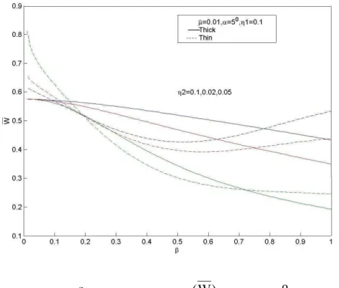
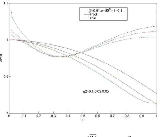
Fig. 2-At damping coefficient r = 1/100, Radial displacement
(
W
)
vs. wave number (
) with
2as parameterFig. 4- At damping coefficient r = 10, Radial displacement
(
W
)
vs. wave number (
) with
2as parameterFig. 6- At damping coefficient r = 100, Radial displacement
(
W
)
vs. wave number (
) with
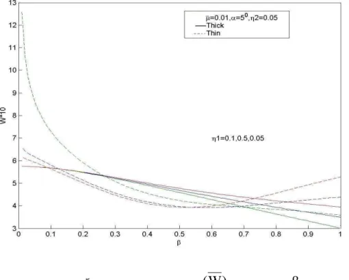
2as parameterFig. 8- At damping coefficient r = 1/100, Radial displacement
(
W
)
vs. wave number (
) with
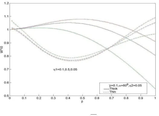
1as parameter
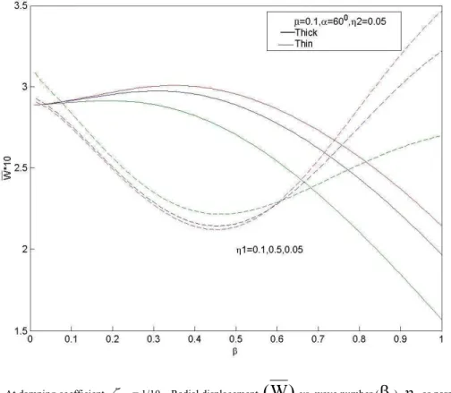
Fig. 10- At damping coefficient r = 1/10, Radial displacement
(
W
)
vs. wave number (
) with
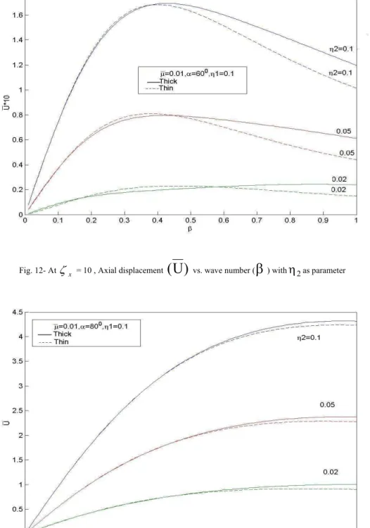
1as parameterFig. 12- At
x = 10 , Axial displacement(
U
)
vs. wave number (
) with
2as parameterFig. 14- At
x = 1/10 and at small angle of incidence , Axial displacement(
U
)
vs. wave number (
) with
2as parameterFig. 15- At
x = 1/10 and at small angle of incidence Axial displacement(
U
)
vs. wave number (
) with
2as parameter
Fig. 16- At x = 100 Axial displacement
(
U
)
vs. wave number (
) with
2as parameterFig. 18 – At x= 1/10 axial displacement
(
U
)
vs. wave number (
) with
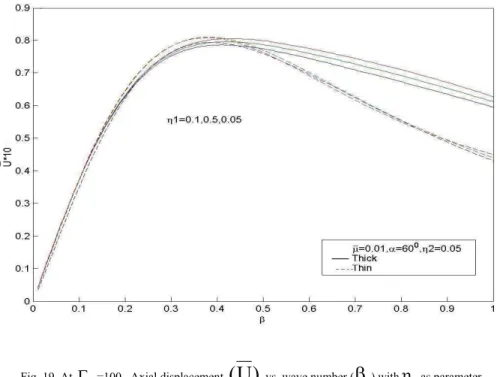
1as parameterFig. 20- At
x = 100 Axial displacement(
U
)
vs. wave number (
) with
1as parameter