Transactions of the VŠB – Technical University of Ostrava, Mechanical Series No. 1, 2013, vol. LIX
article No. 1941
Drahomír RYCHECKÝ*, Aleš MUSIL**
RELIABILITY OF MECHANICAL STRUCTURES WITH CONSIDERING SEISMIC LOADING SPOLEHLIVOST STROJNÍCH KONSTRUKCÍ P I UVAŽOVÁNÍ SEIZMICKÉHO
ZAT ŽOVÁNÍ
Abstract
The paper deals with summarization of methods used in seismic response evaluation of mechanical structures. The seismic evaluation of structures is inseparable condition in the design of hazardous facilities such as nuclear power plants. Based on demanded results, different methods can be used. For instance, when the anchorage of the structure is determinative, the equivalent static method (ESM) can be advantageously used. To evaluate complex seismic response of a large mechanical structure the ESM is un-sufficient and e.g. for steady-state response of the structure the response spectrum method (RSM) can be employed [3]. The RSM combines the response based on known mode shapes. Applying direct time-history (accelerogram) is also possibility but time consuming. The paper contains definition of seismic safety factor for determining safety reserve of structures. All methods are applied on a sample example. Obtained results of each method are compared and discussed.
Abstrakt
Účelem tohoto p ísp vku je shrnutí metod používaných pro posouzení seismické odezvy strojních konstrukcí. Seizmické posouzení konstrukcí je nedílnou součástí p i navrhování rizikových za ízení, jako jsou jaderné elektrárny. Lze užít různých metod podle požadovaných výsledků. Nap íklad, pokud je určující výpočet kotvení, může být s výhodou použita ekvivalentní statická metoda (ESM). Pro posouzení celkové seismické odezvy složitých strojních konstrukcí se však ESM nehodía pro ustálenou odezvu konstrukce je vhodn jší použití metody spekter odezvy (RSM) [3]. RSM kombinuje odezvy známých vlastních tvarů konstrukce. Další možností je zatížení zadané akcelerogramem, které vyžaduje integraci vcelé časové oblasti, což je časov náročné. Součástí p ísp vku je také definice seizmického bezpečnostního faktoru pro určení bezpečnostních rezerv. Všechny metody jsou aplikovány na ukázkovém p íkladu. Získané výsledky každé metody jsou porovnány a objasn ny.
Keywords
Seismic response, equivalent static method, response spectrum method, seismic resistance.
1
INTRODUCTION
Seismicity has large influence on lifetime of civil structures. It can induce extreme loads. Importance of extreme loads is increasing with importance (hazard) of facility (nuclear power plants, water dam, etc.). It is necessary to determine the values of the forces induced by applied seismic
* Ing., Rizzo Associates Czech, a. s., Vejprnická 633/56, Plzeň, tel. (+420) 37 735 0233, e-mail:
** Ing., Rizzo Associates Czech, a. s., Vejprnická 633/56, Plzeň, tel. (+420) 37 735 0233, e-mail:
loading. There are a lot of different methods suitable for the static solution, based on response spectrum or time history of loading. The more exact results let us make the best account of the mechanical structures and design focused on the seismic risk. The seismic resistance is important in industrial facilities such as nuclear power plants, chemical plants and many others facilities located in seismically active zones.
2
METHODS FOR SEISMIC RESPONSE EVALUATION
2.1
Equivalent Static Method (ESM)
This method is suitable for constructional and dynamical simple structures. The method is used for conservative representation of acting seismic forces for evaluation of simple structures or anchorage of equipment which can be assumed rigid. Maximal quasi-static seismic load is the maximal acceleration from the response spectra. The structure can be considered as seismically rigid if the first eigenfrequency is greater than 33 Hz [1]. The force in one direction is calculated as
,
, f i
i
k
m
a
F
(2.1)where:
i
F
– equivalent static load in one direction
N ,k
– coefficient depends on different state’s codes (EN, UBS, IBC, ASCE [1], etc.)
- ,m
– mass of contraction
kg ,f i
a
, – acceleration in multiples ofg
(gravitational acceleration)
m .There are some methods for combination of force for one load case, for example 100% of one force in one direction and 40% in others or the Square-Root-of-the-Sum-of-the-Square (SRSS) for 3D response.
2.2
Response Spectrum Method
The method is more complex and suitable for FEM software than ESM. This method requires knowledge of eigenfrequencies and including missing mass effect for eigenfrequencies higher than 33 Hz [1]. This method is applicable only for linear models. The method involves the calculation of the maximum values of the displacements and member force in each mode using smooth design spectra. The mathematical model of the structure is
),
(
)
(
)
(
)
(
t
B
q
t
Kq
t
F
t
q
M
(2.2)where:
M
– mass matrix,B
– damping matrix,K
– stiffness matrix,)
(t
F
– loading vector,)
(t
q
– displacement vector.mode [3]. Two major problems must be solved in order to obtain an approximate response spectrum solution to this equation:
Estimation of maximum force and displacement for each direction of ground motion, Estimate the maximum response of each component of ground motion acting at the same
time after the response for the tree orthogonal direction is solved.
The mathematical model usually has more than one eigenfrequency lower than 33 Hz [1]. It is necessary to account for all of them. For this case the modal combinations are used. The most conservative method is the sum of absolute of modal response values. Another common approach is to use the Square-Root-of-the-Sum-of-the-Square (SRSS) of the maximum modal values. This approach is not justified for 3D where some eigenfrequencies are identical. Another method is Complete Quadratic Combination (CQC) method that was first published in 1981 [7].
2.3
Time History Load
This method offers direct way for using acceleration, velocity or displacement. The method solves equation (2.2) during the whole time load. Detail progress of solution can be seen for example in [3] or [4]. The results are real responses of the structure. The method can be used also for non-linear models. On the other hand, it is not time efficient because model has to be solved for total time of loading. It is also very time consuming to solve large models. Due to this fact the models have to be simplified.
3
DETERMINATION OF SEISMIC SAFETY FACTOR
The seismic safety factor is an important coefficient of structure reliability. It determines the minimum seismic resistance for each important structure. Calculation of the value of seismic safety factor is carried out as follows:
NS
/
S,
S
C
R
R
F
(2.3)where:
C – limit value of the evaluated response quantity (allowable displacements, forces, stress, etc.), RNS – primary component of the evaluated quantity (without seismicity),
RS – next primary seismic component of the evaluated quantity.
4
SAMPLE EXAMPLE
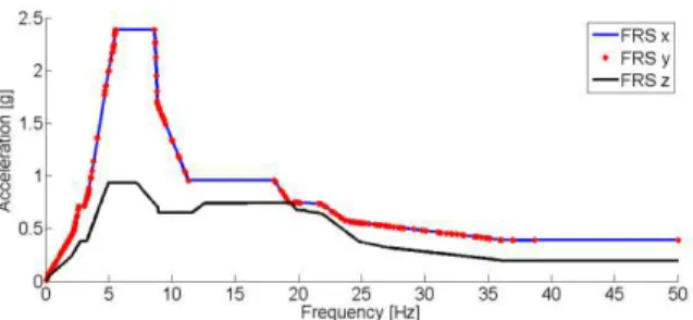
Simple mechanical structure was chosen which can be seen in Fig. 1. The dimensions are in meters. Legs have square cross-section of 0.2 [m] x 0.2 [m] and frame has 0.15 [m] x 0.15 [m]. The construction was loaded by three floor response spectra in three orthogonal directions, Fig. 2. Two horizontal spectra are the same. The maximal amplitude is between 5 and 8 Hz for x and y direction and from 5 to 7 Hz in z direction. Three unique accelerograms were generated, one from each floor response spectrum. This is type of the applied earthquake loading which is assumed to have 30 s.
4.1
Equivalent Static Method
This method was solved in the software SCIA. The maximum values of acceleration from the applied floor response spectra were
a
x,
a
y,
a
z
2
.
39
g
,
2
.
339
g
,
0
.
93
g
. Coefficientk
forFig. 1 Steel structure with dimensions and cross section
Fig. 2 Floor response spectra for each direction
Fig. 3 Stress analysis by ESM
4.2
Response Spectrum Method
This method needs to input eigenfrequencies which are in Tab. 1. The eigenfrequencies were obtained from conservative mathematical model to Eqn. (4.1)
.
0
)
(
)
(
t
Kq
t
q
M
(4.1)Tab. 1 Eigenfrequencies of the structure
Mode No. 1. 2. 3. 4. 5. 6. 7. 8. 9. 10. Frequency
[Hz]
3.93 3.96 4.46 9.29 13.70 23.80 26.69 28.29 28.82 29.75
4.3
Time History Load
The mechanical structure was loaded by generated synthetic accelerogram. Damping was
K
B
10
5*
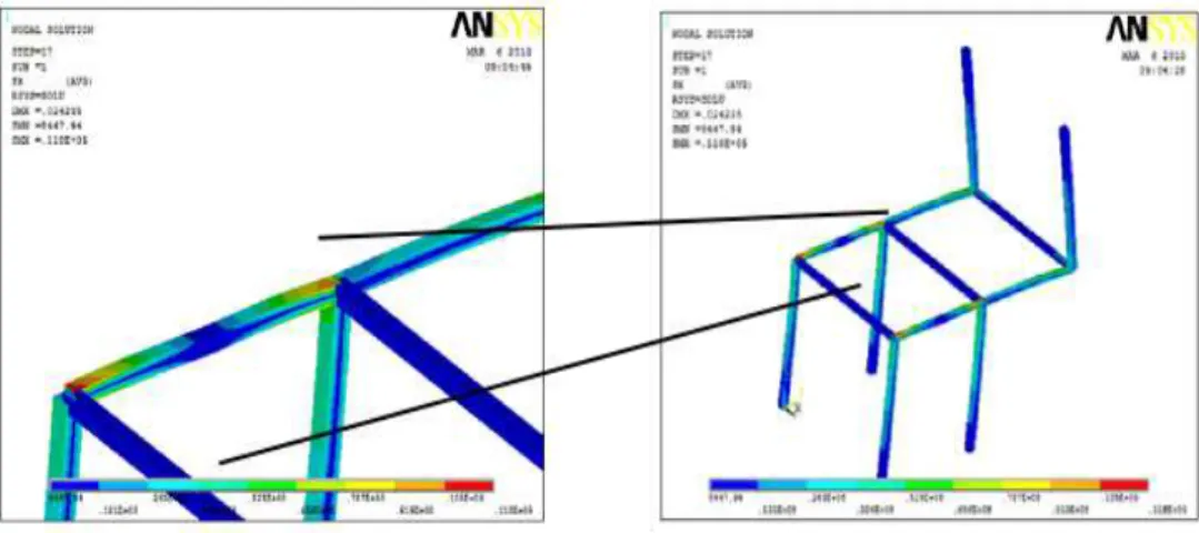
too. Correctly it was expected this method was the slowest one. It generated big amount of results. This is the reason why it is so hard to work with results. On the other hand time range was 30 s and solver was submitted 3000 steps. It means 100 steps per second. More precisely according Nyquist’s theorem the highest frequency included to the results is 50 Hz [2].Fig. 5 Stress analysis by RSM
4.4
The Stress Values for All Methods
The approaches of the mentioned methods are totally different but each of them found out the same most critical part of the structure. The results are very spread due to amount of conservation of each approach. The highest stress can be seen in Tab. 2. The value or difference between ESM and others method is caused by:
including conservative coefficient k=1.2,
the maximal amplitude of acceleration is out of range eigenfrequencies of the structure, for more see in Fig. 2.
The time history analysis has the lowest stress value due to:
the changing shape of the structure has better resistance against excitation, there is not enough time to induce such high displacement compared to the RSM. Tab. 2 Values of Stress in the Structure
Method ESM RSM THL
The Highest Stress [MPa] 265.2 111 62
4.5
Determination of Seismic Resistance
M Pa,
235
1
235
M k
R
C
(4.2)where:
k
R
– yield strength
2 m
kg ,
M
– global reliability of material [7].It is apparent that the structure needs some improvement according to the ESM because the value of limit stress is lower than the highest value in the structure. This is a result of all the conservatisms that were assumed. The
F
S can be determined for RSM and THL. The value of RNS is4.4 MPa. The highest stress induced by seismic loading has the same place as RNS. These values are
established into the (2.3). The values
F
S are in Tab. 3.Tab. 3 Values of coefficients seismic safety coefficient
F
SMethod ESM RSM THL
S
F
[-] Not Defined 2.08 3.725
CONCLUSIONS
The aim of this paper was introducing three main different approaches for seismic evaluations. The seismic resistance is important for many facilities whose damage would have a significant influence on human health and life. Each of the methods was briefly described with their positives and negatives. The results were discussed and clarified. The method for seismic evaluation was shortly presented and reliability of the structure against earthquake event was analyzed by seismic safety factor. This factor is used for the seismic hazard value in the specific location.
REFERENCES
[1] ASCE 4-98 Seismic Analysis of Safety-Related Nuclear Structures and Commentary. Reston : ASCE, 1998. ISBN 0-7844-0433-X.
[2] BALDA, M. Úvod do statistické mechaniky. Plzeň : ZČU, 2001. ISBN 80-7082-820-X. [3] IEC 980-89 Recommended Practices for Seismic Qualification of Electrical Equipment of the
Safety System for Nuclear Generating Stations, 1st ed. Geneve : IEC, 1989. [4] HUMAR, H. L. Dynamics of Structures. New Jersey : Prentice-Hall Inc., 1990.
ISBN 0-13-222068-7.
[5] SLAVÍK, V., STEJSKAL, J., ZEMAN, V. Základy dynamiky strojů. Praha : ČVUT, 1997. ISBN 80-01-01622-6.
[6] STN EN 1993-1-1. Eurokód 3: Navrhování ocelových konstrukcí- Část 1-1: Obecná pravidla
a pravidla pro pozemní stavby, Praha : Ú ad pro technickou normalizaci, metrologii a statní zkušebnictví, 2006.