GMDD
7, 8941–8973, 2014Intel Xeon Phi accelerated WRF
Goddard microphysics
scheme
J. Mielikainen et al.
Title Page
Abstract Introduction
Conclusions References
Tables Figures
◭ ◮
◭ ◮
Back Close
Full Screen / Esc
Printer-friendly Version Interactive Discussion
Discussion
P
a
per
|
Discussion
P
a
per
|
Discussion
P
a
per
|
Discussion
P
a
per
Geosci. Model Dev. Discuss., 7, 8941–8973, 2014 www.geosci-model-dev-discuss.net/7/8941/2014/ doi:10.5194/gmdd-7-8941-2014
© Author(s) 2014. CC Attribution 3.0 License.
This discussion paper is/has been under review for the journal Geoscientific Model Development (GMD). Please refer to the corresponding final paper in GMD if available.
Intel Xeon Phi accelerated Weather
Research and Forecasting (WRF)
Goddard microphysics scheme
J. Mielikainen, B. Huang, and A. H.-L. Huang
Intel Parallel Computing Center, University of Wisconsin-Madison, Madison, Wisconsin, USA Received: 23 October 2014 – Accepted: 17 November 2014 – Published: 12 December 2014 Correspondence to: B. Huang ([email protected])
GMDD
7, 8941–8973, 2014Intel Xeon Phi accelerated WRF
Goddard microphysics
scheme
J. Mielikainen et al.
Title Page
Abstract Introduction
Conclusions References
Tables Figures
◭ ◮
◭ ◮
Back Close
Full Screen / Esc
Printer-friendly Version Interactive Discussion
Discussion
P
a
per
|
Discussion
P
a
per
|
Discussion
P
a
per
|
Discussion
P
a
per
|
Abstract
The Weather Research and Forecasting (WRF) model is a numerical weather predic-tion system designed to serve both atmospheric research and operapredic-tional forecasting needs. The WRF development is a done in collaboration around the globe. Further-more, the WRF is used by academic atmospheric scientists, weather forecasters at 5
the operational centers and so on. The WRF contains several physics components. The most time consuming one is the microphysics. One microphysics scheme is the Goddard cloud microphysics scheme. It is a sophisticated cloud microphysics scheme in the Weather Research and Forecasting (WRF) model. The Goddard microphysics scheme is very suitable for massively parallel computation as there are no interactions 10
among horizontal grid points. Compared to the earlier microphysics schemes, the God-dard scheme incorporates a large number of improvements. Thus, we have optimized the Goddard scheme code. In this paper, we present our results of optimizing the God-dard microphysics scheme on Intel Many Integrated Core Architecture (MIC) hardware. The Intel Xeon Phi coprocessor is the first product based on Intel MIC architecture, and 15
it consists of up to 61 cores connected by a high performance on-die bidirectional in-terconnect. The Intel MIC is capable of executing a full operating system and entire programs rather than just kernels as the GPU does. The MIC coprocessor supports all important Intel development tools. Thus, the development environment is one familiar to a vast number of CPU developers. Although, getting a maximum performance out of 20
MICs will require using some novel optimization techniques. Those optimization tech-niques are discussed in this paper. The results show that the optimizations improved
performance of Goddard microphysics scheme on Xeon Phi 7120P by a factor of 4.7×.
In addition, the optimizations reduced the Goddard microphysics scheme’s share of the total WRF processing time from 20.0 to 7.5 %. Furthermore, the same optimiza-25
tions improved performance on Intel Xeon E5-2670 by a factor of 2.8× compared to
GMDD
7, 8941–8973, 2014Intel Xeon Phi accelerated WRF
Goddard microphysics
scheme
J. Mielikainen et al.
Title Page
Abstract Introduction
Conclusions References
Tables Figures
◭ ◮
◭ ◮
Back Close
Full Screen / Esc
Printer-friendly Version Interactive Discussion
Discussion
P
a
per
|
Discussion
P
a
per
|
Discussion
P
a
per
|
Discussion
P
a
per
1 Introduction
Scientific computing is moving towards the exascale era. In order to prepare legacy software to take full advantage of modern many-core supercomputing environments, the legacy code has to be modernized. This means taking a careful look at the code modernization opportunities. Modern CPU cores contain several Single Instruction Par-5
allel Data (SIMD) execution units for performing the same instruction on multiple data point simultaneously. Intel’s Many Integrated Core Architecture (MIC) accelerator cards up the ante by having up to 61 CPU cores with 16 SIMD execution units per core. Thus, both threading and vectorization techniques are explored in this paper. Furthermore, code has to be optimized for frequent reuse of the cached data to increase computa-10
tional intensity. This issue will also be explored in the paper. In addition, the Intel MIC coprocessor uses the same programming models and tools as processors. Thus, the
optimization effort also benefits the code running on CPUs.
The Weather Research and Forecasting (WRF) is an open source Numerical Weather Prediction (NWP) model. It is suitable for simulating weather phenomena 15
ranging from meters to thousands of kilometers. WRF is the most widely used com-munity weather forecast and research model in the world. Both operational forecasters and atmospheric researcher are using it in 153 countries. The WRF model contains two dynamics cores: the Non-hydrostatic Mesoscale Model core (Janjic, 2003) and the Advanced Research WRF (Wang et al., 2008) core. A dynamic core contains a set of 20
dynamic solvers that operates on a particular grid projection, grid staggering, and ver-tical coordinate system. The WRF model also contains several physics components, many of which can be used with both dynamic cores. The WRF has an extensible de-sign. Therefore, it is possible to add physics, chemistry, hydrology models and other features to it. In the real world scenarios WRF is initialized with boundary conditions 25
GMDD
7, 8941–8973, 2014Intel Xeon Phi accelerated WRF
Goddard microphysics
scheme
J. Mielikainen et al.
Title Page
Abstract Introduction
Conclusions References
Tables Figures
◭ ◮
◭ ◮
Back Close
Full Screen / Esc
Printer-friendly Version Interactive Discussion
Discussion
P
a
per
|
Discussion
P
a
per
|
Discussion
P
a
per
|
Discussion
P
a
per
|
WRF software architecture takes advantage of the distributed and shared memory systems. However, vector capabilities of Xeon Phi coprocessors and the latest CPUs are only used by the WSM5 microphysics scheme. The other modules have not been vectorized at all. In this paper, we present our results of vectorizing and further op-timizing another microphysics scheme, called Goddard scheme, on the current Xeon 5
Phi. Furthermore, with the advent of unified AVX-512 vector extension instructions on Intel’s future Knights Landing MIC and Skylake CPU, utilization of vector processing is becoming essential for a peak performance on data parallel programs such as WRF.
Meanwhile, OpenMP 4.0 offers important solutions for vectorization is a standard way.
These will make our optimization work imperative for optimal performance of the WRF 10
on any future Intel hardware.
Although, Intel Xeon Phi is a new product there are already exists of a lot of publica-tions characterizing its performance. A case study of the WRF on Xeon Phi analyzed
the scalability trade-offs running one or more ranks of an MPI program on an Intel
MIC chip (Meadows, 2012). Currently, the latest community release (WRFV3.6) runs 15
natively on Xeon Phi. However, only WSM5 microphysics scheme has been fully opti-mized to take full advantage of the Intel MIC (Michalakes, 2013). WSM5 contains 1800 lines of code out of an approximately 700 000 in WRF. WSM5 is just one of over ten microphysics schemes in WRF. There are also six other physics components in WRF for a total of seven physics components. In addition, there is also a dynamics core in 20
WRF that has not been optimized for Xeon Phi yet. This paper describes our efforts
to optimize Goddard microphysics scheme to take advantage of the Intel’s MIC. This represents our first step towards fully acceleration WRF on Intel MIC.
Other examples of Intel MIC acceleration are leukocyte tracking using medical imaging techniques (Fang et al., 2014), real-world geophysical application (Weinberg 25
simula-GMDD
7, 8941–8973, 2014Intel Xeon Phi accelerated WRF
Goddard microphysics
scheme
J. Mielikainen et al.
Title Page
Abstract Introduction
Conclusions References
Tables Figures
◭ ◮
◭ ◮
Back Close
Full Screen / Esc
Printer-friendly Version Interactive Discussion
Discussion
P
a
per
|
Discussion
P
a
per
|
Discussion
P
a
per
|
Discussion
P
a
per
tion package (Reida and Bethunea, 2014) and general purpose subroutine system for the numerical solution of the incompressible Navier–Stokes equations (Venetis et al., 2014). In addition, the use of Intel MIC for the computation of the partial correlation
coefficient with information theory (PCIT) method for detecting interactions between
networks has also been explored (Stanzione, 2014). Furthermore, the UCD-SPH uti-5
lizing the Smoothed Particle Hydrodynamics (SPH) method for modelling wave inter-action with an Oscillating Wave Surge Converter (OWSC) device has been optimized for Intel MIC (Lalanne, 2014). Moreover, the performance of Intel MIC vs. CPU has been studied using a parallel simulation of high-dimensional American option pricing (Hu et al., 2014). A fast short-read aligner has also been implemented on Intel MIC 10
(Chan et al., 2014).
WRF modules have a relatively low arithmetic intensity and limited operand reuse. Furthermore, large working set size of WRF modules overflows cache memories of the current coprocessors. Therefore, WRF optimization process will start by modifying the code to expose vectorization and reducing the memory footprint size for better cache 15
utilization. Techniques such as less-than-full-vector loop vectorization have to be used for a peak performance (Tian et al., 2013).
A nice advantage of using Xeon Phi for WRF acceleration is the fact that an improve-ment in the whole WRF can be observed after each optimization step. This is due to WRF running on a Xeon Phi’s native mode. This is one huge advantage of Xeon Phi 20
compared to the GPUs, which we have been using for WRF optimization earlier. Just
like Xeon Phi’s offload mode, an individual GPU kernel needs to transfer data between
CPU and GPU. The data transfer overhead for a WRF module on a GPU is usually enough to kill any potential speedup for the whole WRF. Only when the whole code-base has been translated to run on GPU can WRF get any speedup on GPUs. For 25
Xeon Phis, a speedup can be observed from day one.
GMDD
7, 8941–8973, 2014Intel Xeon Phi accelerated WRF
Goddard microphysics
scheme
J. Mielikainen et al.
Title Page
Abstract Introduction
Conclusions References
Tables Figures
◭ ◮
◭ ◮
Back Close
Full Screen / Esc
Printer-friendly Version Interactive Discussion
Discussion
P
a
per
|
Discussion
P
a
per
|
Discussion
P
a
per
|
Discussion
P
a
per
|
the Goddard scheme are given in Sect. 4. Conclusion and plans for future work are described in Sect. 5.
2 Goddard microphysics scheme
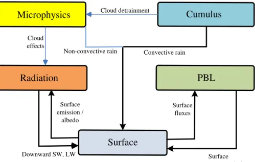
The WRF physics components are microphysics, cumulus parameterization, planetary boundary layer (PBL), land-surface/surface-layer model and short-/longwave radiation. 5
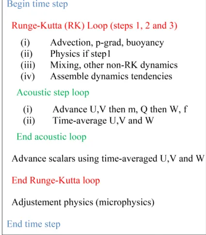
WRF physics components and their interactions are shown in Fig. 1. Dynamics core and its model integration procedure are shown in Fig. 2.
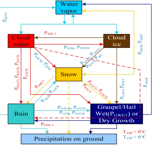
The Goddard microphysics scheme was introduced in (Tao and Simpson, 1993). The microphysical scheme has been modified to reduce the over-estimated and unrealistic amount of graupel in the strati form region (Tao et al., 2003 and Lang et al., 2007). In 10
addition, saturation issues have been addressed better (Tao et al., 2003) and more re-alistic ice water contents for longer-term simulations have been obtained (Zeng, 2008, 2009). The microphysical processes simulated in the model are demonstrated in Fig. 3 and explained in Table 1. The process is a single moment bulk cloud microphysics scheme, which update 7 variables, (deviation of potential temperature, water vapor and 15
mixing ratio of 5 hydrometeors (cloud water, cloud ice, rain water, snow, graupel/hail) in every time step using prognostic equation saturation process and microphysical in-teraction process.
3 Intel MIC
Intel MIC can be programmed using either offload or native programming model.
Com-20
piler directives can be added to the code to mark regions of the region of the code
that should be offloaded to the Intel Xeon Phi coprocessor. This approach is
GMDD
7, 8941–8973, 2014Intel Xeon Phi accelerated WRF
Goddard microphysics
scheme
J. Mielikainen et al.
Title Page
Abstract Introduction
Conclusions References
Tables Figures
◭ ◮
◭ ◮
Back Close
Full Screen / Esc
Printer-friendly Version Interactive Discussion
Discussion
P
a
per
|
Discussion
P
a
per
|
Discussion
P
a
per
|
Discussion
P
a
per
the host using Intel’s compiler with the compiler switch –mmic to generate code for the MIC architecture. After that, the resulting binary is copied to the MIC coprocessor and the binary is executed there. This makes code porting process straightforward, but the
code optimization still takes skill and effort. Furthermore, the latest community release
of WRF (WRF v3.6) already runs natively on Xeon Phi. So, we are taking the current 5
Intel MIC WRF code as a baseline and performing optimizations to individual modules in the WRF code. In this paper code optimization results for Goddard microphysics scheme will be presented.
Intel Xeon Phi coprocessor 7120P, which we used for benchmarks in the paper,
contains 61 independent cores running at a low frequency of ∼1.2 GHz. Each core
10
supports four-way hyperthreading for 244 concurrent threads running of the Intel Xeon Phi. Inside each core there is a dedicated vector unit using 512-bit vector registers for Single Instruction Multiple Data (SIMD) operations. The SIMD instruction set sup-ports data parallel execution of floating point multiplication, addition, fused multiply-add and division, exponential functions, logarithms, trigonometric functions, bitwise logical 15
functions, gather/scatter memory access operations. Bit-masked operations for most operations are also provided (Rahman, 2013).
Furthermore, Intel Xeon Phi has 16 GB of high bandwidth Graphics Double Data Rate (GDDR5) memory. Unified L2 caches in each core are used to cache the access to GDDR5 memory. In addition, each core has L1 cache both for instruction and data, 20
with a typical access time of 1 cycle. The caches are fully coherent and implement x86 memory order model. The memory bandwidth provided by L1 and L2 caches is 15
and 7 times faster than GDDR5 bandwidth. Therefore, effective use of caches is the
optimization feature for achieving the peak performance of Intel Xeon Phi (Chrysos, 2014).
25
Summary of the specifications of the Intel Xeon Coprocessor 7120P is shown in
Ta-ble 2. More details of Intel MIC programming can be found in (Jeffers and Reinders,
bench-GMDD
7, 8941–8973, 2014Intel Xeon Phi accelerated WRF
Goddard microphysics
scheme
J. Mielikainen et al.
Title Page
Abstract Introduction
Conclusions References
Tables Figures
◭ ◮
◭ ◮
Back Close
Full Screen / Esc
Printer-friendly Version Interactive Discussion
Discussion
P
a
per
|
Discussion
P
a
per
|
Discussion
P
a
per
|
Discussion
P
a
per
|
marking the performed Goddard code optimizations. The specifications of the CPU are shown in Table 3.
4 Code optimization
To test Goddard scheme on MIC we used a CONtinental United States (CONUS) benchmark data set for 12 km resolution domain for 24 October 2001. A WRF domain 5
is a geographic region of interest discretized into a 2-dimensional grid parallel to the ground. Each grid point has multiple levels, which correspond to various vertical heights
in the atmosphere. The size of the CONUS 12 km domain is 433×308 horizontal grid
points with 35 vertical levels. As shown in Fig. 4, the test problem is a 12 km resolution 48 h forecast over the Continental US capturing the development of a strong baro-10
clinic cyclone and a frontal boundary that extends from north to south across the entire US Goddard microphysics computation is organized into a 3-dimensional grid where
the microphysical process computations in each column (k-dimension) are processed
independently. Thus, there are two dimensions of parallelism (i- and j-dimensions)
to work with. We used Intel’s Fortran compiler, ifort, version 15.0.0 for compiling the 15
Goddard source code for both Intel Xeon E5-2670 CPU and Intel Xeon Phi 7120P co-processor. For CPU compilation the following default WRF compiler options for ifort
were used: -O3 -openmp -w -ftz -fno-alias -auto -fp-model fast=1 prec-div
-no-prec-sqrt -auto -align array64byte. For Intel MIC the following compiler options from
the WRF v3.6 distribution were used: -mmic -auto -ftz -fno-alias -fimf-precision=low
20
-fimf-domain-exclusion=15 -opt-assume-safe-padding -opt-streaming-stores always
-opt-streaming-cache-evict =0 -mP2OPT_hlo_pref_use_outer_strategy=F -fp-model
fast=1 -no-prec-div -no-prec-sqrt -auto -align array64byte. Dynamic scheduling was
used for OpenMP work sharing construct in a do-loop.
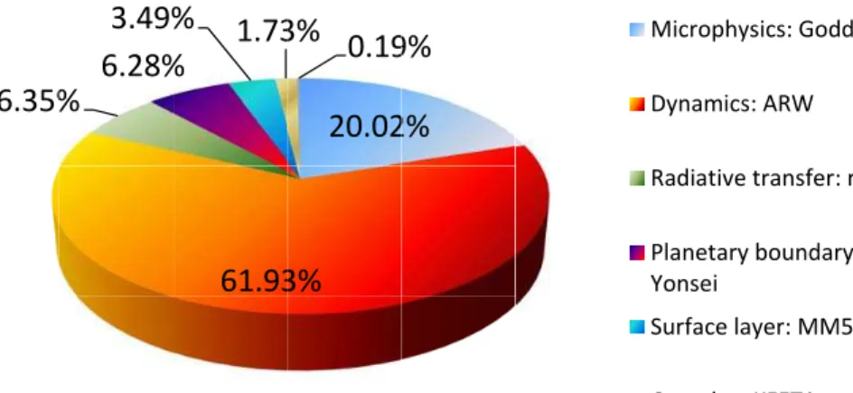
As can be seen from Fig. 5, the microphysics is the most time consuming physics 25
con-GMDD
7, 8941–8973, 2014Intel Xeon Phi accelerated WRF
Goddard microphysics
scheme
J. Mielikainen et al.
Title Page
Abstract Introduction
Conclusions References
Tables Figures
◭ ◮
◭ ◮
Back Close
Full Screen / Esc
Printer-friendly Version Interactive Discussion
Discussion
P
a
per
|
Discussion
P
a
per
|
Discussion
P
a
per
|
Discussion
P
a
per
sists of over 500 000 lines of code. Therefore, it makes sense to optimize Goddard mi-crophysics scheme first as this relatively small module can still give an overall speedup to the whole WRF. A summary of the various optimization steps is shown in Fig. 6. The processing times are an average of 10 execution runs. These processing times are measured running a stand-alone driver for the Goddard scheme. A default domain 5
decomposition of 4 horizontal and 61 vertical tiles were used by the first version of Goddard code (v1).
4.1 Removal of the vertical dimension from temporary vectors for reduced memory footprint
The first optimization step (v2) was modifying the dimensions of some intermediate 10
variables so that the k-dimension of that variable is removed. This process can be
performed for variables that only require the use on onek-dimension value at a time.
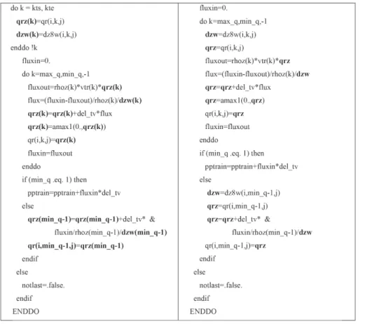
This optimization had the effect of reusing the cached data to increase computational
intensity. An example of this process is shown in Fig. 7. The processing time was reduced from 223.0 to 206.4 ms.
15
4.2 Loop transformations to enable vectorization of affected loops
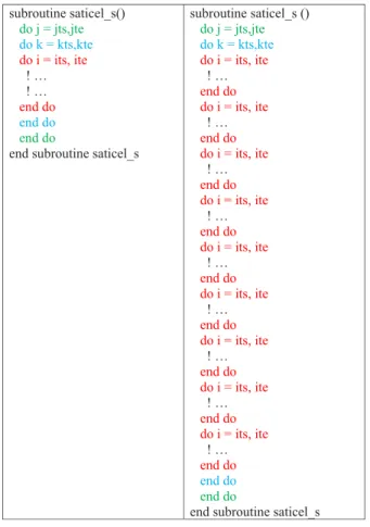
Vectorizing the main subroutine, saticel_s, was done in preparation of the next major optimization step. Vectorization refers to the process where a scalar implementation, which does an operation one pair of operands at a time, is converted to a vector pro-cess, where a single instruction can refer to a vector. This adds a form of parallelism to 20
software in which one instruction or operation is applied to multiple pieces of data. The
benefit is more efficient data processing and improved code performance.
In this optimization step, ani-loop nested inside j- and l-loops were split into nine
separatei-loops. This is illustrated in Fig. 8. This allows the compiler to vectorize those
innermost loops ini-dimension.
GMDD
7, 8941–8973, 2014Intel Xeon Phi accelerated WRF
Goddard microphysics
scheme
J. Mielikainen et al.
Title Page
Abstract Introduction
Conclusions References
Tables Figures
◭ ◮
◭ ◮
Back Close
Full Screen / Esc
Printer-friendly Version Interactive Discussion
Discussion
P
a
per
|
Discussion
P
a
per
|
Discussion
P
a
per
|
Discussion
P
a
per
|
4.3 Collapsei- andj-loops into smaller cells for smaller footprint per thread
In the next optimization step (v3) input data is copied to vector sized arrays of 16 elements. Each thread will process only 16 data elements. Thus, better data locality is achieved as more of the data can be accessed from the cache memories. In Fig. 9, Goddard multithreaded code for this technique is shown. The drawback of this method 5
is the overhead of copying input data to temporary arrays. Similarly, output data have to be copied from vector size arrays into to the original big arrays. Dynamic scheduling was used for OpenMP work sharing construct in the do-loop. The actual computation is performed in the main Goddard subroutine, saticel_s, 16 grid points at a time.
4.4 Addition of vector alignment directives 10
In the code version (v4) vector alignment directives were added before each i-loop.
So, that the compiler is able to make optimizations for the data access. Data alignment is a method to force the compiler to create data objects in memory on specific byte
boundaries. This is done to increase efficiency of data loads and stores to and from the
processor. This had a bigger effect of the code running on CPU than on MIC.
15
4.5 Additional optimization of temporary variables for reduced memory footprint
In v6, we modified the dimensions of some intermediate variables so that the k
-dimension of that variable is removed. This process can be performed for variables
that only require the use on onek-dimension value at a time. For the CONUS 12 km
20
GMDD
7, 8941–8973, 2014Intel Xeon Phi accelerated WRF
Goddard microphysics
scheme
J. Mielikainen et al.
Title Page
Abstract Introduction
Conclusions References
Tables Figures
◭ ◮
◭ ◮
Back Close
Full Screen / Esc
Printer-friendly Version Interactive Discussion
Discussion
P
a
per
|
Discussion
P
a
per
|
Discussion
P
a
per
|
Discussion
P
a
per
4.6 Code validation
Code validation was performed by checking that all code versions produced the same output values on CPU. During code validation precise math compiler options were used. This tells the compiler to strictly adhere to value-safe optimizations when im-plementing floating-point calculations. It disables optimizations that can change the re-5
sult of floating-point calculations, which is required for strict ANSI conformance. These semantics ensure the reproducibility of floating-point computations, including code vec-torized or auto-parallelized by the compiler. However, this compiler options slows down the performance. Therefore, the WRF does not use this compiler option as a default option.
10
This is in stark contrast to a situation when the default WRF compiler options are used, which tells the compiler to use more aggressive optimizations when
implement-ing floatimplement-ing-point calculations. These optimizations increase speed, but may affect the
accuracy or reproducibility of floating-point computations.
4.7 Effects of the code optimization on CPU performance 15
Figure 10 shows the effect of the compiler optimizations on CPU performance. The
overall speedup from the code optimization on an Intel Xeon E5-2670 CPU was 2.8×
compared to 4.7×on the Intel Xeon Phi 7120P. The fact that the same code
optimiza-tions also improved CPU performance indicates that the single source code for both CPU and MIC is a reality. This reduces development costs as any programming work 20
done to modernize WRF for MICs will also improve its performance on legacy CPUs.
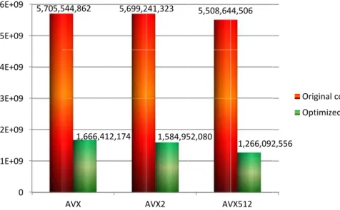
4.8 Analysis using instruction mix report from Intel Software Development Emulator
GMDD
7, 8941–8973, 2014Intel Xeon Phi accelerated WRF
Goddard microphysics
scheme
J. Mielikainen et al.
Title Page
Abstract Introduction
Conclusions References
Tables Figures
◭ ◮
◭ ◮
Back Close
Full Screen / Esc
Printer-friendly Version Interactive Discussion
Discussion
P
a
per
|
Discussion
P
a
per
|
Discussion
P
a
per
|
Discussion
P
a
per
|
and optimized Goddard source code. Instruction counts are shown for AVX, AVX2 and AVX512 instructions sets Instruction count reduction for AVX512 instruction set is quite small for the original code due to limited vectorization of the code. However, the op-timized code has a lower instruction count because of the use of vector instructions
instead of scalar instructions. Furthermore, AVX512 offers significantly improved code
5
vectorization capabilities as is evident from its low instruction count compared to AVX and AVX2 instruction counts on the optimized code.
4.9 The best processing times both on one and two socket CPU configurations and Intel MIC
In Fig. 12, a summary of total elapsed times for execution of Gorrard calculation on 10
Xeon CPU with 1 socket and 2 socket configurations and on Intel MIC. The results show that the scaling from a single CPU socket to a dual socket configuration is less than optimal due to memory bound nature of the code. Before the code optimization was performed, a dual socket CPU was faster than MIC. However, after the optimiza-tion process the performance of MIC is even higher than a dual socket CPU configura-15
tion. Furthermore, the relative performance increase from the code optimizations was higher for the Intel MIC than CPUs. Thus, the performed optimizations are even more important on MIC due to its larger speedup benefit from those optimizations.
4.10 Performance effects of multi-threading and vectorization
In Fig. 13, effects of orthogonal optimization techniques of multi-threading and
vector-20
GMDD
7, 8941–8973, 2014Intel Xeon Phi accelerated WRF
Goddard microphysics
scheme
J. Mielikainen et al.
Title Page
Abstract Introduction
Conclusions References
Tables Figures
◭ ◮
◭ ◮
Back Close
Full Screen / Esc
Printer-friendly Version Interactive Discussion
Discussion
P
a
per
|
Discussion
P
a
per
|
Discussion
P
a
per
|
Discussion
P
a
per
heights in performance beyond that of an Intel Xeon processor, but it required both multi-threading and vectorization to achieve that.
4.11 Performance effects of the optimization of Goddard microphysics scheme on the WRF
The optimized Goddard microphysics code was incorporated back into the WRF. In-5
tel’s VTune profiles measurements in Fig. 14, show that after code optimizations God-dard scheme takes only 7.6 % of the total processing time and dynamics is even more dominant at 71.5 % share of the total processing time. Thus, it is a natural candidate for further optimization of the WRF. In addition, both radiative transfer and planetary
boundary layer are also two physics categories that warrant further optimization efforts
10
as they both take over 7 % of the total processing time.
5 Conclusions
We have shown in this paper that Intel MIC can be faster than a dual socket CPU system. However, to achieve that, both multi-threading and vectorization have to uti-lized. Furthermore, code has to be optimized for frequent reuse of the cached data 15
to increase computational intensity. Following there guidelines, the optimization of the WRF Goddard microphysics scheme was described in this paper.
The results show that the optimizations improved performance of Xeon Phi 7120P by
4.7×. This translates into 1.15×increase in total WRF processing time. Furthermore,
the optimizations improved performance on Intel Xeon E5-2670 by a factor of 2.8×. The
20
GMDD
7, 8941–8973, 2014Intel Xeon Phi accelerated WRF
Goddard microphysics
scheme
J. Mielikainen et al.
Title Page
Abstract Introduction
Conclusions References
Tables Figures
◭ ◮
◭ ◮
Back Close
Full Screen / Esc
Printer-friendly Version Interactive Discussion
Discussion
P
a
per
|
Discussion
P
a
per
|
Discussion
P
a
per
|
Discussion
P
a
per
|
The generic nature of the performed optimizations means that the optimized code
will run efficiently on future Intel MICs and CPU. The next generation Intel MIC,
In-tel Knights Landing (KNL), is not fully compatible with the previous generation, since
AVX-512 SIMD instructions on KNL are encoded differently than the Larrabee New
Instructions (LRBni). However, it is expected that the optimization that we have per-5
formed so far on the code will also run well on KNL. The future Intel CPUs, such as Skylake-EX, will also use the AVX-512 instruction encoding for vector instructions.
The Goddard microphysics scheme optimization work represents an initial step to-wards fully vectorizing the WRF. As could be seen from the speedup figures, optimiza-tion of the code is essential for a good performance on the MIC and modern CPUs. 10
Thus, the work will continue in the optimization of the other WRF modules.
Acknowledgements. This work is supported by Intel Corporation under Grant No. MSN171479 to establish the Intel Parallel Computing Center at the University of Wisconsin-Madison. The authors would like to thank Bob Burroughs and Michael Greenfield for generous support.
References 15
Borovska, P. and Ivanova, D.: Code Optimization and Scaling of the Astrophysics Software Gadget on Intel Xeon Phi, Partnership for Advanced Computing in Europe (PRACE), 136 pp., 2014.
Borovska, P., Gancheva, V., and Tsvetanov, S.: Optimization and Scaling of Multiple Sequence Alignment Software ClustalW on Intel Xeon Phi, Partnership for Advanced Computing in 20
Europe (PRACE), 138 pp., 2014.
Chan, S. H., Cheung, J., Wu, E., Wang, H., Liu, C., M. Zhu, X., and Lam, T. W.: MICA: a fast short-read aligner that takes full advantage of Intel Many Integrated Core Architecture (MIC), arXiv preprint, 1402, 2014.
Chrysos, G.: Intel®Xeon Phi™ Coprocessor – the Architecture, Intel Whitepaper, 2014. 25
GMDD
7, 8941–8973, 2014Intel Xeon Phi accelerated WRF
Goddard microphysics
scheme
J. Mielikainen et al.
Title Page
Abstract Introduction
Conclusions References
Tables Figures
◭ ◮
◭ ◮
Back Close
Full Screen / Esc
Printer-friendly Version Interactive Discussion
Discussion
P
a
per
|
Discussion
P
a
per
|
Discussion
P
a
per
|
Discussion
P
a
per
Hu, Y., Li, Q., Cao, Z., and Wang, J.: Parallel simulation of high-dimensional American option pricing based on CPU versus MIC, in: Concurrency and Computation: Practice and Experi-ence, 2014.
Janjic, Z. I.: A nonhydrostatic model based on a new approach, Meteorol. Atmos. Phys., 82, 271–285, 2003.
5
Jeffers, J. and Reinders, J.: Intel Xeon Phi Coprocessor High Performance Programming, Morgan-Kauffman, Newnes, 2013.
Koesterke, L., Koltes, J. E., Weeks, N. T., Milfeld, K., Vaughn, M. W., Reecy, J. M., and Stanzione, D.: Discovery of biological networks using an optimized partial correlation co-efficient with information theory algorithm on Stampede’s Xeon and Xeon Phi processors, in: 10
Concurrency and Computation: Practice and Experience, 2014.
Lalanne, C., Rafiee, A., Dutykh, D., Lysaght, M., and Dias, F. L.: Enabling the UCD-SPH code on the Xeon Phi, Partnership for Advanced Computing in Europe (PRACE), 131 pp., 2014. Lang, S., Tao, W.-K., Cifelli, R., Olson, W., Halverson, J., Rutledge, S., and Simpson, J.:
Improv-ing simulations of convective system from TRMM LBA: easterly and Westerly regimes, J. 15
Atmos. Sci., 64, 1141–1164, 2007.
Meadows, L.: Experiments with WRF on intel®Many Integrated Core (Intel MIC) Architecture, OpenMP in a Heterogeneous World, 130–139, 2012.
Michalakes, J.: Optimizing Weather Models for Intel Xeon Phi, Intel Theater Presentation SC ’13, 20 November 2013.
20
Rahman, R.: Intel®Xeon Phi™ Coprocessor Architecture and Tools: the Guide for Application Developesr, Apress, 2013.
Reida, F. and Bethunea, I.: Optimising CP2K for the Intel Xeon Phi, Partnership for Advanced Computing in Europe (PRACE), 140 pp., 2014.
Skamarock, W. C., Klemp, J. B., Dudhia, J., Gill, D. O., Barker, D. M., Duda, M. G., Huang, X., 25
Wang, W., and Powers, J. G.: A description of the Advanced Research WRF Version3, NCAR Technical Note, TN-4475+STR, Boulder, Colorado, USA, 2008.
Tao, W. K. and Simpson, J.: The Goddard cumulus ensemble model, Part I: Model description, Terr. Atmos. Ocean. Sci., 4, 35–72, 1993.
Tao, W.-K., Simpson, J., Baker, D., Braun, S., Chou, M. D., Ferrier, B., and Wetzel, P.: Micro-30
GMDD
7, 8941–8973, 2014Intel Xeon Phi accelerated WRF
Goddard microphysics
scheme
J. Mielikainen et al.
Title Page
Abstract Introduction
Conclusions References
Tables Figures
◭ ◮
◭ ◮
Back Close
Full Screen / Esc
Printer-friendly Version Interactive Discussion
Discussion
P
a
per
|
Discussion
P
a
per
|
Discussion
P
a
per
|
Discussion
P
a
per
|
Tian, X., Saito, H., Preis, S. V., Garcia, E. N., Kozhukhov, S. S., Masten, M., Cherkasov, A. G., and Panchenko, N.: Practical SIMD vectorization techniques for Intel® Xeon Phi coproces-sors, in: IEEE 27th International Parallel and Distributed Processing Symposium Workshops & PhD Forum (IPDPSW), 1149–1158, 2013.
Venetis, I. E., Goumas, G., Geveler, M., and Ribbrock, D.: Porting FEASTFLOW to the In-5
tel Xeon Phi: Lessons Learned, Partnership for Advanced Computing in Europe (PRACE), 139 pp., 2014.
Weinberg, V., Allalen, M., and Brietzke, G.: Towards Porting a Real-World Seismological Ap-plication to the Intel MIC Architecture, Partnership for Advanced Computing in Europe (PRACE), 141 pp., 2014.
10
Zeng, X., Tao, W.-K., Lang, S., Hou, A., Zhang, M., and Simpson, J.: On the sensitivity of Atmo-spheric ensemble to cloud microphysics in long-term cloud-resolving model simulations, J. Meteor. Soc. Jpn. A, 86, 45–65, 2008.
Zeng, X., Tao, W.-K., Zhang, M., Hou, A. Y., Xie, S., Lang, S., Li, X., Starr, D., Li, X., and Simpson, J.: The indirect effect of ice nuclei on atmospheric radiation, J. Atmos. Sci., 66, 15
GMDD
7, 8941–8973, 2014Intel Xeon Phi accelerated WRF
Goddard microphysics
scheme
J. Mielikainen et al.
Title Page
Abstract Introduction
Conclusions References
Tables Figures
◭ ◮
◭ ◮
Back Close
Full Screen / Esc
Printer-friendly Version Interactive Discussion
Discussion
P
a
per
|
Discussion
P
a
per
|
Discussion
P
a
per
|
Discussion
P
a
per
Table 1.Key to Fig. 3.
Symbol Meaning
PIMLT Melting of cloud ice to form cloud water.
PIDW Depositional growth of cloud ice at expense of cloud water.
PIHOM Homogeneous freezing of cloud water to form cloud ice.
PIACR Accretion of rain by cloud ice; produces snow or graupel depending on the amount of rain.
PRACI Accretion of cloud ice by rain; produces snow or graupel depending on the amount of rain.
PRAUT Auto-conversion of cloud water to form rain.
PRACW Accretion of cloud water by rain.
PREVP Evaporation of rain.
PRACS Accretion of snow by rain; produces graupel if rain or snow exceeds threshold.
PSACW Accretion of cloud water by snow. Also enhances snow melting.
PSACR Accretion of rain by snow. Produces graupel if rain or snow exceeds threshold; if not, produces snow. Also, the accreted water enhances snow melting.
PSACI Accretion of cloud ice by snow.
PSAUT Auto-conversion (aggregation) of cloud ice to form snow.
PSFW Bergeron process (deposition and riming)-transfer of cloud water to form snow.
PSFI Transfer rate of cloud ice to snow through growth of Bergeron process embryos.
PSDEP Depositional growth of snow.
PSSUB Sublimation of snow.
PSMLT Melting of snow to form rain.
PGAUT Auto-conversion (aggregation) of snow to form graupel.
PGFR Probabilistic freezing of rain to form graupel.
PGACW Accretion of cloud water by graupel.
PGACI Accretion of cloud ice by graupel.
PGACR Accretion of rain by graupel.
PGACS Accretion of snow by graupel.
PGSUB Sublimation of graupel.
PGMLT Melting of graupel to form rain.
GMDD
7, 8941–8973, 2014Intel Xeon Phi accelerated WRF
Goddard microphysics
scheme
J. Mielikainen et al.
Title Page
Abstract Introduction
Conclusions References
Tables Figures
◭ ◮
◭ ◮
Back Close
Full Screen / Esc
Printer-friendly Version Interactive Discussion
Discussion
P
a
per
|
Discussion
P
a
per
|
Discussion
P
a
per
|
Discussion
P
a
per
|
Table 2.Specifications of the Intel Xeon Coprocessor 7120P.
Hardware attribute Value Number of cores 61 Frequency of cores 1.238 GHz GDDR5 memory size 16 GB Number of hardware threads per core 4
SIMD vector registers 32 (512-bit wide) per thread context Flops/cycle 16 (double precision), 32 (single precision)
Theoretical peak performance 1 TFlops s−1(double precision), 2 TFlops s−1(single precision)
L2 cache per core 512 KB
GMDD
7, 8941–8973, 2014Intel Xeon Phi accelerated WRF
Goddard microphysics
scheme
J. Mielikainen et al.
Title Page
Abstract Introduction
Conclusions References
Tables Figures
◭ ◮
◭ ◮
Back Close
Full Screen / Esc
Printer-friendly Version Interactive Discussion
Discussion
P
a
per
|
Discussion
P
a
per
|
Discussion
P
a
per
|
Discussion
P
a
per
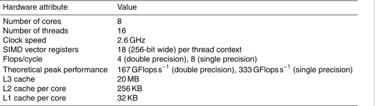
Table 3.Specifications of the Intel Xeon E5-2670.
Hardware attribute Value Number of cores 8 Number of threads 16 Clock speed 2.6 GHz
SIMD vector registers 18 (256-bit wide) per thread context Flops/cycle 4 (double precision), 8 (single precision)
Theoretical peak performance 167 GFlops s−1(double precision), 333 GFlops s−1(single precision)
GMDD
7, 8941–8973, 2014Intel Xeon Phi accelerated WRF
Goddard microphysics
scheme
J. Mielikainen et al.
Title Page
Abstract Introduction
Conclusions References
Tables Figures
◭ ◮
◭ ◮
Back Close
Full Screen / Esc
Printer-friendly Version Interactive Discussion
Discussion
P
a
per
|
Discussion
P
a
per
|
Discussion
P
a
per
|
Discussion
P
a
per
|
Microphysics
Cumulus
Radiation
Surface
PBL
Cloud detrainment
Cloud effects
Convective rain Non-convective rain
Downward SW, LW
Surface fluxes
Surface temperature, wind Surface
emission / albedo
GMDD
7, 8941–8973, 2014Intel Xeon Phi accelerated WRF
Goddard microphysics
scheme
J. Mielikainen et al.
Title Page
Abstract Introduction
Conclusions References
Tables Figures
◭ ◮
◭ ◮
Back Close
Full Screen / Esc
Printer-friendly Version Interactive Discussion
Discussion
P
a
per
|
Discussion
P
a
per
|
Discussion
P
a
per
|
Discussion
P
a
per
|
GMDD
7, 8941–8973, 2014Intel Xeon Phi accelerated WRF
Goddard microphysics
scheme
J. Mielikainen et al.
Title Page
Abstract Introduction
Conclusions References
Tables Figures
◭ ◮
◭ ◮
Back Close
Full Screen / Esc
Printer-friendly Version Interactive Discussion
Discussion
P
a
per
|
Discussion
P
a
per
|
Discussion
P
a
per
|
Discussion
P
a
per
|
5 T
6.35%
c
%
6.28%
3.49%
e
61.93
%
%
1.73
e r
20.02
3%
3%
0.19
F
2%
9%
e I
Microphy
Dynamics
Radiative
Planetary Yonsei
Surface la
Cumulus:
i
ysics: Godda
s: ARW
e transfer: r
y boundary
ayer: MM5
: KFETA
ard
rtm
layer:
GMDD
7, 8941–8973, 2014Intel Xeon Phi accelerated WRF
Goddard microphysics
scheme
J. Mielikainen et al.
Title Page
Abstract Introduction
Conclusions References
Tables Figures
◭ ◮
◭ ◮
Back Close
Full Screen / Esc
Printer-friendly Version Interactive Discussion
Discussion
P
a
per
|
Discussion
P
a
per
|
Discussion
P
a
per
|
Discussion
P
a
per
223
206.4
52.6 52.5 48.3 47.8
0 50 100 150 200 250
v1 v2 v3 v4 v5 v6
Pr
oc
e
ssi
ng
time
[ms
]
Version number of the Goddard scheme code at various optimization stages
GMDD
7, 8941–8973, 2014Intel Xeon Phi accelerated WRF
Goddard microphysics
scheme
J. Mielikainen et al.
Title Page
Abstract Introduction
Conclusions References
Tables Figures
◭ ◮
◭ ◮
Back Close
Full Screen / Esc
Printer-friendly Version Interactive Discussion
Discussion
P
a
per
|
Discussion
P
a
per
|
Discussion
P
a
per
|
Discussion
P
a
per
|
1
subroutine saticel_s() do j = jts,jte
do k = kts,kte
do i = its, ite ! … ! … end do
end do end do
end subroutine saticel_s
subroutine saticel_s () do j = jts,jte
do k = kts,kte
do i = its, ite ! … end do do i = its, ite ! … end do do i = its, ite ! … end do do i = its, ite ! … end do do i = its, ite ! … end do do i = its, ite ! … end do do i = its, ite ! … end do do i = its, ite ! … end do do i = its, ite ! … end do
end do end do
end subroutine saticel_s
Figure 8. The original non-vectorized code is shown on the left. Vectorized code is shown on 2
the right. 3
4
Figure 8.The original non-vectorized code is shown on the left. Vectorized code is shown on the right.
GMDD
7, 8941–8973, 2014Intel Xeon Phi accelerated WRF
Goddard microphysics
scheme
J. Mielikainen et al.
Title Page
Abstract Introduction
Conclusions References
Tables Figures
◭ ◮
◭ ◮
Back Close
Full Screen / Esc
Printer-friendly Version Interactive Discussion
Discussion
P
a
per
|
Discussion
P
a
per
|
Discussion
P
a
per
|
Discussion
P
a
per
|
1
!$OMP PARALLEL DO & !$OMP PRIVATE ( ic, j, ii, i, k ) &
!$OMP PRIVATE ( th1d, qv1d, ql1d, qr1d, qi1d, qs1d, qg1d, rho1d, pii1d, p1d ) & !$OMP SCHEDULE(dynamic,1)
DO ip = 1,((1+(ite-its+1)/CHUNK)*CHUNK)*(jte-jts+1),CHUNK j = jts+(ip-1)/((1+(ite-its+1)/CHUNK)*CHUNK)
IF ( j .ge. jts .and. j .le. jte ) THEN
ii = its+mod((ip-1),((1+(ite-its+1)/CHUNK)*CHUNK)) do k = kts, kte
DO ic=1,min(CHUNK,ite-ii+1) i = ii+ic -1
th1d(ic,k) = th(i,k,j) qv1d(ic,k) = qv(i,k,j) ql1d(ic,k) = ql(i,k,j) qr1d(ic,k) = qr(i,k,j) qi1d(ic,k) = qi(i,k,j) qs1d(ic,k) = qs(i,k,j) qg1d(ic,k) = qg(i,k,j) rho1d(ic,k) = rho(i,k,j) pii1d(ic,k) = pii(i,k,j) p1d(ic,k) = p(i,k,j) ENDDO enddo
IF ( min(CHUNK,ite-ii+1) .gt. 0 ) THEN
call SATICEL_S( dt_in, ihail, itaobraun, ice2, istatmin, & new_ice_sat, id, & th1d, qv1d, ql1d, qr1d, & qi1d, qs1d, qg1d, & rho1d, pii1d, p1d, itimestep, & kts, kte, kms, kme, min(CHUNK,ite-ii+1) )
ENDIF do k = kts, kte
DO ic=1,min(CHUNK,ite-ii+1) i = ii+ic -1
th(i,k,j) = th1d(ic,k) qv(i,k,j) = qv1d(ic,k) ql(i,k,j) = ql1d(ic,k) qr(i,k,j) = qr1d(ic,k) qi(i,k,j) = qi1d(ic,k) qs(i,k,j) = qs1d(ic,k) qg(i,k,j) = qg1d(ic,k) ENDDO
enddo ENDIF ENDDO ! ip_loop
Figure 9. Fortran code for multithreading using OpenMP. Input data is copied to vector sized 2
GMDD
7, 8941–8973, 2014Intel Xeon Phi accelerated WRF
Goddard microphysics
scheme
J. Mielikainen et al.
Title Page
Abstract Introduction
Conclusions References
Tables Figures
◭ ◮
◭ ◮
Back Close
Full Screen / Esc
Printer-friendly Version Interactive Discussion
Discussion
P
a
per
|
Discussion
P
a
per
|
Discussion
P
a
per
|
Discussion
P
a
per
207.8
179.3 176.2
83.4 76.5 73.7
0 50 100 150 200 250
v1 v2 v3 v4 v5 v6
Pr
ocessing
ti
me
[ms]
Version number of the Goddard scheme code at various optimization stages
GMDD
7, 8941–8973, 2014Intel Xeon Phi accelerated WRF
Goddard microphysics
scheme
J. Mielikainen et al.
Title Page
Abstract Introduction
Conclusions References
Tables Figures
◭ ◮
◭ ◮
Back Close
Full Screen / Esc
Printer-friendly Version Interactive Discussion
Discussion
P
a
per
|
Discussion
P
a
per
|
Discussion
P
a
per
|
Discussion
P
a
per
|
1 0 1E+09 2E+09 3E+09 4E+09 5E+09 6E+09
a 0
9 9 9 9 9
9 5,705,5
AVX 544,862
1,666,4
n A 5,699,2
412,174
AVX2 241,323
1,584,95
AV 5,508,64
52,080
VX512 44,506
1,266,0922,556 Orig
Opt
ginal code
timized code
GMDD
7, 8941–8973, 2014Intel Xeon Phi accelerated WRF
Goddard microphysics
scheme
J. Mielikainen et al.
Title Page
Abstract Introduction
Conclusions References
Tables Figures
◭ ◮
◭ ◮
Back Close
Full Screen / Esc
Printer-friendly Version Interactive Discussion
Discussion
P
a
per
|
Discussion
P
a
per
|
Discussion
P
a
per
|
Discussion
P
a
per
1 i
Ela
p
sed
time
[ms
]
a t
0 50 100 150 200 250 300 350 400
X
p
[]
k
Xeon E5‐26 socket, 8 co
372.9
o a
70 (1 ores)
123.2
Original
e o
Xeon E5‐2
sockets, 16
207.8
code O
G C
2670 (2
6 cores) 80
73.7
Optimized c
c C
Xeon Ph
22
code
hi 7120P
23
47.8
GMDD
7, 8941–8973, 2014Intel Xeon Phi accelerated WRF
Goddard microphysics
scheme
J. Mielikainen et al.
Title Page
Abstract Introduction
Conclusions References
Tables Figures
◭ ◮
◭ ◮
Back Close
Full Screen / Esc
Printer-friendly Version Interactive Discussion
Discussion
P
a
per
|
Discussion
P
a
per
|
Discussion
P
a
per
|
Discussion
P
a
per
|
1 c Vect
Scal Vecto
Scala
o C or and Mul ar and Mul or and Singl ar and Singl
n u ti‐threaded ti‐threaded e‐threaded e Threaded
a d 0 d d d d
79.3 237.3
98.1 207.8
768.2
Xeon E
q M 5000
659 2
3422.8
P
E5‐2670
l 10000 98.4
Processing t
Xeon Phi
l g
15000
time [ms]
7120P
r 20000
2
25000 21819.8
GMDD
7, 8941–8973, 2014Intel Xeon Phi accelerated WRF
Goddard microphysics
scheme
J. Mielikainen et al.
Title Page
Abstract Introduction
Conclusions References
Tables Figures
◭ ◮
◭ ◮
Back Close
Full Screen / Esc
Printer-friendly Version Interactive Discussion
Discussion
P
a
per
|
Discussion
P
a
per
|
Discussion
P
a
per
|
Discussion
P
a
per
1 g
7.34%
7.26%
o n
%
%
4.04%
m
%
2.00
W
71.
% 0.22%
c
7.52%
.61%
%
i
%
a
Microphys
Dynamics:
Radiative t
Planetary
Yonsei Surface lay
n
sics: Godda
: ARW
transfer: rrt
boundary la
yer: MM5
rd
tm
ayer: