INTEGRATED DESIGN & CONTROL OF A BUCK BOOST CONVERTER
Martín J. Pomar Garcia
∗ [email protected]Gloria Gutierrez
† [email protected]Julio E. Normey-Rico
∗César de Prada
†∗Depto. de Automação e Sistemas, Universidade Federal de Santa Catarina,
88040-900, Florianópolis, SC, Brazil
†Depto. de Ingeniería de Sistemas y Automática, Universidad de Valladolid,
c/ Real de Burgos s/n, 47011, Valladolid, Spain
ABSTRACT
This paper presents the integrated design and control of a buck boost converter (BBC). In the proposed methodology the design tool provides simultaneously the controller tuning and BBC design parameters in such a way that some closed-loop pre-specified static and dynamic behavior is obtained. This approach contrasts with the traditional methodology, where the design of BBC is performed without taking into ac-count its dynamical behavior. An optimization procedure is used to obtain the electronic components of the BBC and the tuning parameters of the controller, minimizing an objective function that considers the set of performance specifications. Although the methodology can be applied to any converter and any control strategy, in this particular case an ideal BBC and a Sliding Model Control (SMC) strategy are used. Some simulation results show the advantages and principally the flexibility that can be obtained with this approach.
KEYWORDS: integrated process and control design, process optimization, sliding mode control, buck-boost
1
INTRODUCTION
Switched mode DC-to-DC power converters are used in many electric power supply systems, including vehicles,
il-Artigo submetido em 18/02/2009 (Id.: 00957) Revisado em 15/03/2009, 24/04/2009, 13/05/2009
Aceito sob recomendação do Editor Associado Prof. Luis Antonio Aguirre
lumination, control systems, computers, and others systems (Villalva and Ruppert, 2008; Rosemback et al., 2008; Coelho et al., 2008; Russi et al., 2005). Due to their wide range of operating conditions and demanding performance specifica-tions, they have to be designed carefully. At the same time, because of their intrinsic nonlinearity, these systems repre-sent a challenging field for control algorithms (Buso, 1999). Several proven design methods as well as control strategies have been proposed in the last years in the literature for these processes (Zanatta and Pinheiro, 2008). A general purpose fuzzy controller is presented in (Mattavelli et al., 1997) to obtain a high performance voltage control in a BBC. A ro-bust controller based on aµ-synthesis approach is presented in (Buso, 1999) using a linear model of the BBC. A nonlinear model predictive controller is used in (Pomar, 2005) that can be used for different topologies without changes in the con-troller structure. Nonlinear approaches based on SMC have been proposed in several papers (Shtesssel et al., 2002; Sht-esssel et al., 2003; Ahamed et al., 2003). These applications are motivated by the special advantages of the SMC in treat-ing variable structure systems like the DC-to-DC converters. These systems present discontinuities in their operation, so that the corresponding model changes its structure according to the mode of operation (Itkis, 1976; Utkin, 1974 (English Translation 1978)).
to improved robustness and performance over a wide range of operation conditions.
Traditionally the design of a controlled DC-DC converter is done in two steps. In the first step the structure of the system is defined and the components (capacitor, inductor, etc) are computed to obtain, in steady state, a desired set of specifi-cations such as ripple, nominal voltage, etc. In the second step a dynamical model of the converter is computed and a controller is tuned to achieve a set of transient specifications, such as rise time and over shoot. Sometimes the obtained closed-loop performance is not satisfactory as the adequate functioning of the DC-DC converter in closed loop, does not depend exclusively on the kind of controller and its parame-ters, since the control of a process is conditioned by its own design (Luyben and Floudas, 1994; Skogestad and Postleth-waite, 1997).
This traditional design of the DC-DC converter and its con-troller follows the last two of the three fundamental steps which are necessary to develop a plant: the process synthesis, the process design and the process control. In the synthesis the engineer defines the interconnection between the differ-ent units of the system and the characteristics of the differdiffer-ent units. The process design consists of computing the operat-ing conditions of the different units and their dimensions in order to attempt certain production objectives. The process control design has an objective to impose some transient and permanent operation conditions to the plant such as stability or disturbance rejection capability (Gutierrez, 2000). In the DC-DC case the process design step gives the circuit struc-ture and components value whereas the process control step gives the structure and tuning of the controller.
This traditional design method ignores the idea that changes in the DC-DC converter design can make the system eas-ier to be controlled or provide more degrees of freedom for enhanced performance (Luyben, 1993). Thus, a more appro-priate approach is to look for the solution for the problem of design and control in closed loop in one step, besides provid-ing the optimal parameters of the circuit and of the controller. That is, the controller design and tuning are also included into the plant design problem with the aim of providing the lower costs solution besides guaranteeing certain closed loop dynamic specifications. This methodology is known as in-tegrated design, where both the process design and control design are made in one step taking into account at the same time the operating conditions as well as the control specifi-cations.
The first ideas for integrating control with process design were put forward by (Nishida and Ichikawa, 1975; Nishida et al., 1976). (Marselle et al., 1982) was the first in defin-ing the control problem in a process for a network of heat
exchangers. (Shefield, 1992) provided an industrial perspec-tive on the need to integrate system design and control. Both (Morari, 1992) and (Perkins, 1989) have gathered together some of the results and previous efforts concerning the inter-action between design and control. (Morari, 1983; Skoges-tad and Morari, 1987; Morari and Zafiriou, 1989; SkogesSkoges-tad et al., 1991; Skogestad and Wolf, 1992) have made signifi-cant contributions to control analysis and to the study of the dynamic adaptability of systems, introducing and analyzing control magnitudes for the interaction of the variables and the rejection of disturbances.
Nevertheless, in the electronic devices area, very few con-tributions appear in the literature. Thus, the main objective of this paper is to show that the closed-loop operation of DC-DC converters can be improved if the integrated design methodology is used. Particularly, this contribution presents an integrated process-control design methodology applied to a BBC with an SMC strategy, considering its dynamic behav-ior in closed loop. Several control and operation conditions are used in the design to show the flexibility of the proposed approach. Moreover, to evaluate the obtained performance the obtained results are compared to the ones presented in recent papers.
It is important to note that the methodology presented in this paper for the BBC and the SMC strategy can be applied to any other power converter and any other control strategy (Pomar et al., 2007).
The paper is organized as follows: section 2 presents the BBC description and modeling. Section 3 gives results of the BBC traditional design approach with the sliding mode controller. Then, section 4 presents the integrated de-sign methodology and the associated optimization problem and section 5 gives simulation results comparing both ap-proaches. The paper ends with some conclusions.
2
BUCK-BOOST CONVERTER
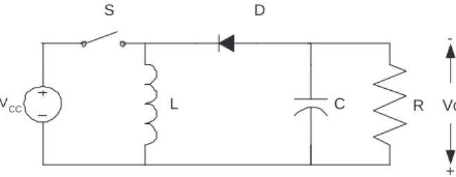
Figure 1 shows the circuit of an ideal BBC, which, for sim-plicity, has been chosen in this paper to illustrate the pro-posed methodology which is not dependant on the process model. The BBC is a typical DC-to-DC converter normally used as a power supply with adjustable output voltage (Vo)
that can be higher or lower than the supply voltage (Vcc).
From the control point of view the objective of this system is to provide an output that can follow a desired voltage ref-erence and reject the disturbances caused by the load varia-tions, represented in Figure 1 by the resistanceR. To perform this task, an adequate control strategy actuating on the switch Smust be defined.
R
S D
C
L Vo
-+
VCC
Figure 1: Ideal Buck Boost Converter (BBC).
iLin the inductorLis not zero, the BBC operates in
continu-ous conduction mode. Otherwise, a discontinucontinu-ous operation mode is considered.
Typically, two BBC models are described in the litera-ture: the so-called instantaneous, and the average model (Borges, 2002; Rosemback et al., 2008). The instantaneous model considers all the dynamic phenomena related to the switch operation. The average model does not consider the switch dynamics but only the dominant behavior caused by the other elements of the circuit and is normally used when PWM based controllers are applied to the BBC (Middlebrook and Cúk, 1976; Kassakian et al., 1991; Vorpérian, 1990). In this paper only the instantaneous model is described as the proposed SMC controller is based on this type of model. The instantaneous model is obtained using the following proce-dure.
First defineqas a signal that characterizes the dynamic be-havior of the switch:
S :
q(t) = 0, if the switch is open q(t) = 1, if the switch is closed
Thus, three sets of differential equations describe the behav-ior of the BBC:
Ifq= 0the capacitor discharges throughLandRand there are two different cases. IfiL 6= 0(continuous conduction
mode):
diL
dt =
1
LvC (1)
dvC
dt =
1
C(−iL− vC
R) (2)
V0 = −vC (3)
however ifiL= 0(discontinuous conduction mode):
diL
dt = 0 (4)
dvC
dt = −
vC
RC (5)
V0 = −vC (6)
Finally, ifq= 1the diode isolatesRandL: diL
dt =
1
LVcc (7)
dvC
dt = −
1
C vC
R (8)
V0 = −vC (9)
The simulations in this paper are computed using the com-bination of these three sub-systems. Note that the proposed methodology can cope with the BB control behavior both in the continuous conduction mode and discontinuous conduc-tion mode.
3
SEQUENTIAL BBC DESIGN AND SMC
TUNING
3.1
BBC Design
Traditional design of a BBC like the one in Figure 1 starts with a given set of specifications such as:
• Voltage sourceVcc,
• Output voltage operating rangeV0∈[V0min, V0max],
• Load operating rangeR∈[Rmin, Rmax],
and implies determining the value of the components of the circuit, that is: inductanceLand capacitanceC, such that the desired steady state requirements are fulfilled.
In this paper we use the BBC presented in (Mattavelli et al., 1997), whose parameters are given in Table 1. This
Element Value
Input voltage (Vcc) 12V
Resistance (min. value) (Rmin) 20Ω
Resistance (max. value) (Rmax) 150Ω
Output voltage (Vo) 20V
Inductance (H) 360µH
Capacitor (C) 100µF
Max. switching frequency (fSmax) 50kHz
Table 1: BBC parameters.
particular BBC has been chosen in order to compare the per-formance of the proposed control design to the one presented in (Mattavelli et al., 1997) using a general purpose fuzzy con-troller.
3.2
Sliding mode control
method-ology. It is not the objective of this paper to analyze in depth the SMC; however, in the following paragraphs, a brief ex-planation of the main ideas of this controller is given.
Essentially, sliding mode control computes the value of the manipulated variables that steer the system trajectories to-ward a surface, or subset of the state space, where the target is located and where the system naturally evolves toward its target (da Cunha et al., 2005).
In order to illustrate the technique, let’s consider the dynam-ical system given by (Mattavelli et al., 1993):
˙
x=f(x, t, u) (10)
where:
x∈D⊆Rnis the state vector. f :D×Rn→Rnis a vector function. uis the control input.
Now, let’sσ(x, t) : D×R → Rbe a continuous function with non-zero gradient inD, and let’s define the sliding sur-face:
SL={(x, t)∈D×R, σ(x, t) = 0} (11)
containing the desired target. A sliding mode controller will implement a control law given by:
u(x, t) =
u+(
x, t) if σ(x, t)>0
u−(x, t) if σ(x, t)<0 (12)
such that, if the system trajectories deviate from the sliding surfaceSL, the controlu will drive them back toSL,
ap-proaching the target.
Due to the duality of control actions, the system model will present a discontinuity alongSL:
f(x, t, u) =
f+(
x, t, u+)
if σ(x, t)→0+
f−(x, t, u−) if σ(x, t)→0− (13)
Obviously, in order to send the current state back to the slid-ing surface, the system trajectories in both subspacesf+and
f−should be directed towardSL, hence, it should happens:
lim
σ→0+
dσ dt <0
⇒ lim
σ→0σ
dσ dt <0
lim
σ→0−
dσ dt >0
(14)
Then, the set:
Ω ={(x, t)∈D×R, σ(x, t) ˙σ(x, t)<0} (15)
defines the region where a sliding mode could exist. So, the domain of the sliding modes is given by:
ψ=S∩Ω (16)
Figure 2: Basic BBC control structure.
A system driven by the control law (12) will ideally com-mute infinitely fast on both sides ofSL. In practice, a high
frequency switching, known as chattering, takes place.
3.3
Design of a SMC for the BBC
Figure 2 shows a schema of a possible sliding mode con-troller of the BBC.
In this case, the surface SL is a linear combination of the
state variables, inductor current and capacitor voltage, which describes a commutation curve in the state space:
SL={(x, t)∈D×R, σ(x, t) =k(iL−iLe)+(vC−vCe) = 0}
(17) where(iLe, vCe)is the desired operating point in steady state
andkis a design parameter that can be computed by impos-ing the existence condition (15). Notice that the target point satisfies (17).
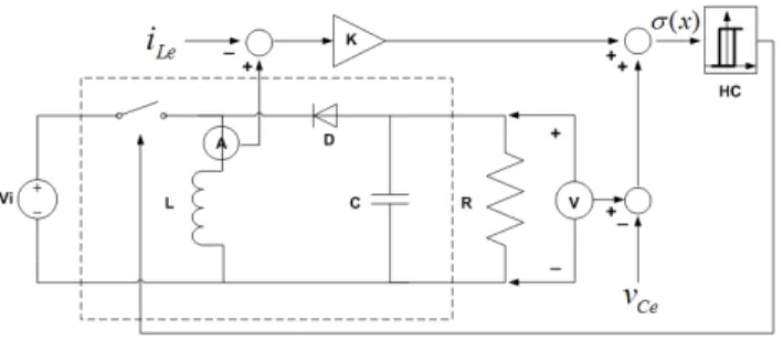
This control structure needs a reference value for the inductor current that in practice is difficult to evaluate, since it gener-ally depends on load power demand, supply voltage and load voltage. To overcome this problem, in a practical implemen-tation, the inductor current error goes through a high pass filter (HPF) forcing its average value in steady state to zero, which if (17) is enforced, will force the output voltage to its set point too. In this case the final value of the current in steady state is defined by the load conditions without affect-ing the slidaffect-ing surface value. The SMC structure with the filter is shown in figure 3. This filter adds a new tuning pa-rameter: the filter time constantτthat can affect the system behaviour (Mattavelli et al., 1993). Note that this filter must allow a fast response and at the same timeτmust be higher than the switching period. A practical rule for computingτ is to choose a value in the vicinity of the natural frequency of the system.
Nevertheless, due to the hysteresis (18), it may happen that the average value of SL be different from zero, so that a
prob-Figure 3: Simulated BBC control structure.
lem can be tackled by placing a PI controller (see figure 3) on the signal representingσ(x, t), acting only when the state is onSL, so that the dynamics of the systems during transients
is not modified.
In order to limit the chattering phenomena, the control law (12) is formulated with a small hysteresis, as it can be seen in Figure 3,2βbeing the corresponding width:
q(t) =
0 if σ(x, t)>+β
1 if σ(x, t)<−β (18)
where in our case for simulation:β= 0.1.
Finally, as shown in the SMC schema, the circuit incorpo-rates a limiter of the maximum inductor current. The com-plete structure is used for the simulations in the following sections.
The complete tuning of the SMC consisting of the tuning of the PI controller, the filter and the gain ofSL can be done
using traditional methodologies (Spiazzi et al., 1997; Borges and Pagano, 2002; Tan et al., 2006) or an optimization pro-cess as it will be shown in section 4.
3.4
Traditional SMC tuning
In order to compare the performance of the different con-trollers in this paper the SMC tuning procedure presented in (Spiazzi et al., 1997) is used.
Firstkandτare chosen in order to have an adequate closed-loop performance at the operating point defined byVoandR
using (Spiazzi et al., 1997):
k < − L
RC D D′
τ > RC
D′2
D R+ (2−D
′) L
RC
D′ D
where:D= VO
VO+Vcc andD ′
= 1−D.
In our case as the BBC operates atVo = 20V and forR =
20ΩandR = 150Ω, two different tuning are obtained, one for each load. kandτ which attend the conditions in both cases have been selected as final tuning parameters. In the second step the PI controller is tuned using classical linear control design. The obtained values are shown in table 2.
Parameter Value k −0.45
τ 3.6∗10−4
Kp 500
Ki 3000
Table 2: Traditional SMC tuning
4
INTEGRATED DESIGN TAKING
CON-TROL
REQUIREMENTS
INTO
AC-COUNT
In section 3, BBC circuit design and control system design were performed as a two-step independent process. Only af-ter the circuit was designed, the task of finding the param-eters of the controller was started, constrained by the limits imposed by the designed BBC. An alternative is to integrate both phases computing simultaneously the sizing of the BBC components and the tuning of the controllers satisfying both, operational and control constraints.
4.1
Closed Loop Design
To guarantee an adequate performance in the whole op-erational range of the BBC, a design methodology named “multi-point design” will be introduced in this section. The main idea of this “multi-point design” is to consider the closed-loop operation of the controlled BBC in a set of pos-sible operation conditions. Thus, one of the objectives of the design is to achieve the desired performance in all these op-eration conditions.
The key elements of the proposed integrated design method-ology are:
sub-jected to modifications. In this case we consider the structure in Figure 3.
2. A dynamical mathematical model of the process is for-mulated. In our case it corresponds to the set of equa-tions (1-9).
3. The control structure is defined and the mathematical model is enhanced with the controller equations. The resulting closed loop model behavior depends on yet un-known process and control parameters.
4. Specifications and operability constrains, regarding both the process steady state and dynamic response, are added, being formulated at a set of chosen operating points covering the desired functioning range.
5. The selection of the process and control parameters is done by optimization of a cost function that can reflects both economic and performance aims.
This methodology leads to a dynamic non-linear optimiza-tion problem in terms of the dynamic variables of the closed-loop system and the decision variable, which now includes both the unknown circuit and control system parameters, un-der the constraints of the dynamic model and the closed-loop specifications, either in equality or inequality form. The gen-eral form of this problem is:
Minimize F(z, x, u)
z Subject to:
dynamic process model dynamic control law g(z, x, u)≤0
h(z, x, u) = 0
z∈Rn
(19)
wherez is the decision variable,xthe state variable andu is the control input, g(z, x, u)and h(z, x, u) represent re-spectively the specification and operation constraints. This optimization can be solved with appropriate sequential or si-multaneous methods.
4.2
Closed loop integrated design of the
SMC-BBC
The integrated circuit and controller design of the BBC with a SMC is done solving the optimization problem (19) where the decision variable z = [L, C, k, τ, Kp, Ki]T includes
the process parameters[L, C]and the controller parameters
[k, τ, Kp, Ki]. The dynamic model of the process is given by
equations (1-9) while the control law is given by equations (17-18). To complete the problem formulation the objective function and the constraints have to be defined.
4.2.1 The objective function
The selection of an adequate cost function is very important for the proposed methodology. As one of the main charac-teristics of a power converter is its capacity to reject distur-bances, the objective function F(z, x, u)is defined using a disturbance rejection index that computes the ISE (Integral Quadratic Error) for a particular simulation situation. In this case two representative simulation experiments are chosen covering the worst extreme operating situations of the BBC when it is working withVO= 20V
The simulations consider a step load change between20and
150Ωwhich is considered the worst dynamic disturbance for the controller, that this, the faster change in the load with the maximum amplitude. Thus, two cases are considered:
1. with a set point of20V, the loadRwas changed from
20Ωto150Ωatt= 10ms.
2. with a set point of20V, the loadRwas changed from
150Ωto20Ωatt= 20ms.
Then, performance terms are included in the cost func-tionF(z, x)of (19), which corresponds to the accumulated quadratic errors in the two representative experiments cover-ing the worst extreme operatcover-ing situations:
F(z, x, u) =λ
Z tf
ti
e2
i1dt+
Z tf
ti
e2
v1dt+
+λ
Z tf
ti
e2
i2dt+
Z tf
ti
e2
v2dt (20)
whereti= 10ms andtf = 30ms. The errorseare defined as
the differences between the set point (desired output current iLej and voltagevCej,j = 1,2) and the actual value of this
current and voltage computed with the closed-loop model:
eij=iLej −iL, j= 1,2
evj =vCej −vC, j = 1,2
The experiment starts at the initial pointiL = 0, vc = 0at
t = 0. Note thatF(z, x, u)includes a measure of relevant dynamic responses. Although the main objective of the con-troller is to obtain the faster load rejection in the output volt-age, it is also important to maintain theiLripple under a
de-sired value. This objective is achieved including the current error inF(x, z, u). For tuning purposes a weighting factorλ is included inF(x, z, u)allowing to achieve a compromise between faster voltage transients and small current ripple.
different operating conditions, guaranteeing the desired per-formance in all of them. This objective is very difficult to achieve using traditional SMC design.
Exhaustive simulations were performed to test the obtained solution under different load conditions. The simulation re-sults corroborated that the worst dynamic situations were ob-tained for the extreme load cases, the ones chosen for the def-inition of the cost function. Thus, it is possible to guarantee that the obtained solution gives the desirable performance for all possible load conditions.
To complete the optimization procedure the set of operation constraints must be defined.
4.2.2 Constrains of the non-linear optimization problem
The dynamic performance is computed only in terms of the cost function F(z, x, u), (20), which can be work out, for a given value of the decision variable z = [L, C, k, τ, Kp, Ki]T, by simulation of the closed loop
sys-tem of Figure 3 for each of the two experiments already men-tioned. In the analyzed case only inequality constraints are considered to obtain positive values ofL, C, τ, Kp, Ki and
negative values ofkin the desired range for each parameter.
For the solution of the optimization problem the function fminsearch.m is used. fminsearch.m is one of the available optimization functions of the MATLABroptimization
tool-box.
The block diagram shown in Figure 4 illustrates the proce-dure used to obtain the optimal value of the parameters. Note that the strategy combines simulations of the closed-loop sys-tem and the evaluation of the cost function in a recursive manner.
The functionf minsearchsolves a non-linear unconstrained optimization problem considering a given cost function and an initial condition (z0). In this case the cost functionJ =
obj(z)is computed using the ISE index and the BBC volt-age and current obtained in the simulation. The operation constraints in this case study are included in the simulation closed-loop model, as for instance, the maximal value of the current. The blockJ =obj(z)needs, for each step, the vec-tor with the values of the process and control parameters (z) computed byf minsearchand the values of the current and voltage for the simulation experiment.
The optimum design parameters, obtained with the proposed method, are given in table 3 for three different values ofλ. As can be seen, asλincreasesLincreases andCdecreases, which means, as expected, a smaller ripple iniL. As it will
be shown in the simulations the price to pay for this is slower
Figure 4: Block diagram of the procedure used to obtain the optimal value of the parameters.
Parameter λ= 0.001 λ= 0.01 λ= 0.1
L 123.84µH 186.23µH 234.29µH C 306.11µF 289.86µF 257.80µF k −0.0773 −0.0983 −0.2133
τ 6.3019∗
10−5
1.1623∗ 10−4
1.0330∗ 10−4
Kp 1
.1020∗
10+3 1.8827∗10
3
714.4854
Ki 104.5357 −704.6957 302.0579
Table 3: Integrated design solution for the SMC BBC
voltage transients.
In the next section some comparative results are performed. An optimal tuning of the SMC design is compared to the SMC tuning presented in section 3 and also to the fuzzy con-troller presented in (Mattavelli et al., 1997).
4.3
Optimal tuning of the SMC for the
tra-ditional design procedure
In order to obtain the best performance of the SMC in the traditional design procedure, the tuning ofk, τ, Kp, Ki can
values of the original design, and using a new cost function:
F(z, x, u) =
Z tf
ti
e2
v1dt+
Z tf
ti
e2
v2dt (21)
with the same constraints, model and controller, as in the previous case. Note that iL is not used in F(z, x, u)
be-cause in this case, asL andC are given, the current rip-ple is also given. Thus, in this case we only look for the best set of tuning parametersk, τ, Kp, Kifor a given BBC.
In the optimization problem the decision variablez is now z = [k, τ, Kp, Ki]. Therefore, in the comparative analysis
we present in the following section we can be sure that the improvement in the performance is due to the integrated de-sign approach and not only due to the correct tuning of the controller parameters.
The obtained values in this case are shown in table 6. This
Parameter Value k −0.3887
τ 3.7285∗10−4
Kp 538.9976
Ki 3.0869∗10+3
Table 4: Solution of optimal traditional design problem with SMC
OSMC solution can be compared to the traditional SMC (TSMC) tuning presented in section 3 and the Fuzzy con-troller (FC) presented in (Mattavelli et al., 1997).
Table 5 shows some comparative indexes when these three controllers are used in the same simulation test: with a set point of20V, the loadRwas changed from20Ωto150Ωat t= 10ms and from150Ωto20Ωatt= 20ms.
Controller Peak (V) Settling time (ms)
TSMC 0.8 1.5
OSMC 0.8 1.5
FC 1.3 2.5
Table 5: Comparative analysis between TSMC, OSMC and FC
This comparative analysis shows that the TSMC approach can achieve almost optimal performance when a unique op-eration point is considered (in this caseVref = 20V).
Note that the closed-loop performance of the OSMC is better than the one obtained using the FC. Also note that another ad-vantage of the SMC approach is that it is a simpler controller which can be implemented in cheap analogical devices.
Next section presents some simulations and more details of this analysis.
5
SIMULATION RESULTS
Comparative responses of the integrated design SMC solu-tion (IDSMC) with the cost funcsolu-tion defined in the previous section for different tuning parameters are shown in this sec-tion. Then we present some modifications in the cost func-tion to include other performance indices and to show the flexibility of the proposed design.
5.1
IDSMC tuning
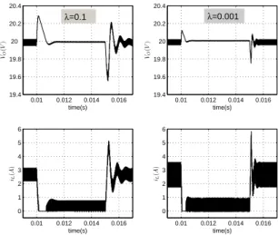
Figure 5 shows some experiments, with changes in the load between20and150Ωand vice versa. As we can see, the bet-ter performance in bet-terms of the voltage transients is obtained, as expected, for the caseλ= 0.001. In this case the current ripple has the higher amplitude, which is also expected be-cause we alow higher values of the current error.
On the other hand the slower voltage transients and smaller current ripple are obtained for the caseλ= 0.1as the weight-ing penalizes the current error. Figures 6 and 7 show in detail the transient response and the steady state in the two exper-iments for the case withλ= 0.001andλ = 0.1which are the extreme cases in terms of current ripple.
Note that the steady state value of the switch (fs) has similar
values in all the simulated cases and it is always less than50
kHz.
Note that the obtained performance in these simulations is
0.01 0.012 0.014 0.016 19.4
19.6 19.8 20 20.2 20.4
time(s) VO
(
V
)
0.01 0.012 0.014 0.016 0
1 2 3 4 5 6
time(s) iL
(
A
)
0.01 0.012 0.014 0.016 19.4
19.6 19.8 20 20.2 20.4
time(s) VO
(
V
)
0.01 0.012 0.014 0.016 0
1 2 3 4 5 6
time(s) iL
(
A
)
λ=0.001 λ=0.1
0.01 0.0105 0.011 0.0115 19.6 19.8 20 20.2 time(s) VO ( V )
0.02 0.0205 0.021 0.0215 19.6 19.8 20 20.2 time(s) VO ( V )
0.01 0.0102 0 1 2 3 4 time(s) iL ( A )
0.02 0.0205 0.021 0.0215 0 1 2 3 4 5 6 time(s) iL ( A )
IDSMC (λ=0.001) IDSMC (λ=0.1)
ˆ
VO= 19.55V
ˆ
VO= 19.78V
ˆ
VO= 20.12V
ˆ
VO= 20.29V
Figure 6: Transient response detail.
0 0.5 1 1.5 2 time(s) iL ( A ) 2 3 4 5 time(s) iL ( A ) 0 0.5 1 1.5 2 2.5 time(s) Control Signal 0 0.5 1 1.5 2 2.5 time(s) Control Signal
IDSMC for λ=0.001 IDSMC for λ=0.1
IDSMC for λ=0.001 IDSMC for λ=0.1
fS=45.46kHz f
S=33.33kHz
fS=32.26kHz f
S=30.33kHz
Figure 7: Steady state detail.
better than in the OSMC previously presented. The obtained improved performance of the IDSMC has a physical inter-pretation: the obtainedLandCof the IDSMC are different from the ones used in the OSMC which are chosen using only steady state specifications. It is clear then that the best design is obtained when a certain compromise between steady-state operation and closed-loop performance is achieved. This is one of the major advantages of the proposed approach, that can include several design specifications in an optimization problem.
Moreover, this example shows the flexibility of the proposed approach that allows for a SMC design considering time-response specifications without a trial and error tuning of the SMC parameters.
0.005 0.01 0.015 0.02 0.025 0.03 29 30 31 32 33 time(s) vC ( V )
0.005 0.01 0.015 0.02 0.025 0.03 0 5 10 15 time(s) iL ( A ) IDSMC1 IDSMC2
R= 150Ω R= 20Ω R= 150Ω
Figure 8: Output voltage and current for the two IDSMC.
5.2
Improving the Design
The proposed approach based on a multi-point design and a time-based performance index can improve the controller and BBC design in several different situations. Consider for instance that the BBC can also operate in a different voltage set-pointV = 30V and for the same values of the load. The ID can then be modified to introduce the simulation test of the load change at 30 V. This implies the definition of a new cost function:
F(z, x, u) = λ
Z tf
ti
e2i1dt+
Z tf
ti
e2v1dt
+ λ
Z tf
ti
e2
i2dt+
Z tf
ti
e2
v2dt
+ λ
Z tf
ti
e2
i3dt+
Z tf
ti
e2
v3dt
+ λ
Z tf
ti
e2
i4dt+
Z tf
ti
e2
v4dt (22)
that considers the voltage and current errors in the four ex-periments. That isei1,ev1,ei2,ev2are the same error as in
(20) andei3, ev3, ei4, ev4 are the errors in the load
distur-bance test at the set point30V. The initial and final times are respectivelyti = 5ms andtf = 30ms.
used (λ= 0.1) and shown in the simulations.
Note that, as the IDSMC1 has been designed only for the caseV = 20V, it shows an unstable and undesirable inductor current behavior when operating inV = 30V. As it can be seen in figure 8, when the inductor current achieves10A, the current limiter actuates and this causes a new switching at this point. This undesirable behavior is avoided when the new operating point is considered in the controller design, as it can be observed in the dotted lines of figure 8 (IDSMC2 case).
The optimum design parameters of the IDSMC2 are given in table 6 forλ= 0.1.
Parameter λ= 0.1
L 234.29µH C 257.80µF k −0.2133
τ 1.0330∗10−4
Kp 714.4854
Ki 302.0579
Table 6: Tuning parameters for the IDSMC2
Alternatively, an optimization procedure under the model and specification constraints can be used to choose such a set with an economic criterion. The problem could be for-mulated as in the previous cases but with a new cost function Fn(x, z, u) = F(x, z, u) +Fc(z), whereFc(z)can
repre-sent, for instance, the price of the components or any other valuable measure of performance or benefit.
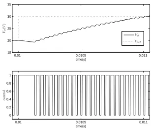
The IDSMC2 with the tuning presented in table 6 can also be used to analyze the closed-loop performance for set-point changes. This is a particular important point as it can show how the proposed control strategy compensates the so-called “non-minimum phase behavior" of the BB. This dynamic be-havior is usually modeled through a right half plane zero in the linearized model of the BB relating the duty cycle (control action) with the voltage output (process variable) (Pomar, 2005). In the IDSMC case it is not necessary to explicitly consider this effect because the linearized model is not used in the design. On the other hand, the minimization of the objective function, which weighs the error(Vref−VO)
during the transient, minimizes this effect. Figure 9 shows a simulation where two changes in the set-point (from20V to
30V and from30V to20V) are used.
As it can be seen the “non-minimum phase behavior" is at-tenuated. Note that the “inverse peak" remains smaller than
1V and its effect disappears in approximately0.2ms. Figure 10 shows a detail of this simulation. Note that just after the changes in the set point the switch is ON and this causes a
0.01 0.011 0.012 0.013 0.014 0.015 0.016 0.017 15
20 25 30 35
time(s) VO
(
V
)
0.01 0.011 0.012 0.013 0.014 0.015 0.016 0.017 0
0.2 0.4 0.6 0.8 1
time(s)
co
n
tr
o
l
VO
Vref
Figure 9: Output voltage and control before a change in the reference.
voltage decrease during a short period of time necessary to drive the energy to the inductor.
6
CONCLUSIONS
The problem of integrated design of a Buck Boost Converter, incorporating control characteristics in closed loop, has been presented in this paper. The optimum design has been ob-tained as the solution for a constrained dynamic optimization problem, where the decision variable incorporates both the physical parameters of the circuit and the tuning parameters of the controller.
0.01 0.0105 0.011
15 20 25 30 35
time(s) VO
(
V
)
0.01 0.0105 0.011
0 0.2 0.4 0.6 0.8 1
time(s)
co
n
tr
o
l
VO
Vref
Although the methodology can be used with any power con-verter and any controller, a sliding mode controller and an ideal BBC have been chosen in this paper to obtain numer-ical results. Note that the use of a different model of the BBC, for example the one that includes the capacitor and in-ductor resistances, does not change the qualitatively obtained results, which mainly shows the advantages of the integrated design over the traditional one.
The simulation results which have been presented in the pa-per showed the advantages of using the integrated design over the traditional sequential approach. In our case study the cost function included only performance terms but, in other cases of integrated design, the aim can be specified also in terms of costs of the components and specifications such as energy consumption. Then the best operating point can be selected by the optimization, fulfilling the constraints.
Additionally, a technique called multi-point design, oriented to cope with the uncertainty of the operation point and load disturbances, has been presented. It allows to take into ac-count different operating conditions, guaranteeing a desired performance in all of them.
The solution for the integrated design problem may not be easy, due, fundamentally, to the size of the problem itself and the non-linearity of the equations it consists of. Math-ematical programming techniques do not always guarantee a global solution to the problem. In addition, the calcula-tion time can be significant. In this sense, we should point out that the design is done off line, so the calculation time is not an important factor at the time of applying this design methodology and other algorithms, such as evolutionary or global ones, can be applied.
ACKNOWLEDGMENTS
The authors wish to thank project ALFA II-0385-FA of the EU and projects DPI2003-00013 and DPI2006-13593 of Spanish CICYT for their support.
The authors, Martín Pomar and Julio E. Normey-Rico, were funded by Agência Nacional do Petróleo e Gás Natural e Bio-combustíveis (ANP), Brazil, under project aciPG-PRH No 34 ANP/MCT.
REFERENCES
Ahamed, M., Kuisma, M., Pyrhonen, O. and Silventoinen, P. (2003). Sliding Mode Control for Buck-Boost Con-verter Using Control Desk dSPACET M, Power Elec-tronics and Drive Systems. PEDS 2003. The Fifth In-ternational Conference on. 2: 1491–1494.
Borges, F. (2002). Analise e Controle de Sistemas de Estru-tura Variável, Dissertação de Mestrado, Universidade Federal de Santa Catarina. .
Borges, F. and Pagano, D. J. (2002). Sliding Mode Con-trol of a Boost Converter with a Washout Filter. (In Portuguese), XV Congresso Brasileiro de Automática. pp. 1638–1643.
Buso, S. (1999). Design of Robust Voltage Controller for a Buck-Boost Converter Usingµ-Synthesis, IEEE Trans-actions on Control Systems Technology. 7(2): 222–229.
Coelho, E., Damasceno, E., Avelar, H. J., Júnior, J. B. V., Camacho, J. R. and Freitas, L. C. (2008). Conversor CC-CC Elevador para Fonte de Energia Baseada em uma Célula a Combustível, XVII Congresso Brasileiro de Automática .
da Cunha, J. P. V. S., Hsu, L., Costa, R. R. and Lizarralde, F. (2005). Controle de Sistemas Lineares Incertos por Modos Deslizantes e Observador de Alto Ganho sem Peaking, Controle & Automação: Revista da Sociedade Brasileira de Automática 16(4): 449–466.
Gutierrez, G. (2000). Diseño Integrado y Síntesis de Pro-cesos Aplicado al Proceso de Fangos Activados, PhD thesis, Universidad de Valladolid.
Itkis, U. (1976). Control Systems of Variable Structure, John Wiley & Sons, New York.
Kassakian, J., Schlecht, M. and Verghese, G. (1991). Princi-ples of Power Electronics, Addison-Wesley.
Luyben, M. L. (1993). Analyzing the Interaction Between Design and Control in Chemical Reactor Systems, PhD thesis, Princeton University.
Luyben, M. L. and Floudas, C. A. (1994). Analyzing the Interaction of Design and Control -1. A Multiobjective Framework and Application to Binary Distillation Syn-thesis, Comp. Chem. Eng. (10): 933–969.
Marselle, D. F., Morari, M. and Rudd, D. F. (1982). Design of Resilient Processing Plants II, Design and Control of Energy Management Systems. Chem. Eng. Sci. 37(259-270).
Mattavelli, P., Rossetto, L., Spiazzi, G. and Tenti, P. (1993). General-Purpose Sliding-Mode Controller for DC-DC Converter Applications, PESC Conf. pp. 609–615.
Mattavelli, P., Rossetto, L., Spiazzi, G. and Tenti, P. (1997). General-Purpose Fuzzy Controller for DC-DC Converters, IEEE Transactions On Power Electronics
Middlebrook, R. and Cúk, S. (1976). A general unified ap-proach to modelling switching-converter power stages, IEEE Power Electronics Specialists Conference - PESC pp. 18–34.
Morari, M. (1983). Design of resilient processing plants-III. A general framework for the assesment of dynamic resilience, Chem. Eng. Sci. 38: 1881–1891.
Morari, M. (1992). Effect of Design on the Controllability of Chemical Plants, IFAC, IFAC Workshop on Interac-tions Between Process Design and Process Control, J. D. Perkins, De., Pergamon Press, pp. 3–16.
Morari, M. and Zafiriou, E. (1989). Robust Process Control, Englewood Cliffs: Prentice-Hall, Inc. .
Nishida, N. and Ichikawa, A. (1975). Synthesis of Optimal Dynamic Process Systems by a Gradient Method, Ind. Eng. Chem. Proc. Des. Dev. 14: 236–242.
Nishida, N., Liu, Y. A. and Ichikawa, A. (1976). Stud-ies in Chemical Process Design and Synthesis II. Op-timal Synthesis of Dynamic Process Systems with Un-certainty, AIChE J. 22: 539–549.
Perkins, J. D. (1989). Interactions Between Process Design and Process Control, International Federation of Auto-matic Control Symposium, Maastricht, Netherlands.
Pomar, M. (2005). Controle Preditivo Não Linear com Aplicação à Eletrônica de Potência, Dissertação de Mestrado, Universidade Federal de Santa Catarina .
Pomar, M., Gutierrez, G., de Prada, C. and Normey-Rico, J. E. (2007). Integrated Design & Control Applied to a Buck Boost Converter, European Conferene Control, ECC .
Rosemback, R. H., Rodrigues, M. C. B. P. and Barbosa, P. G. (2008). Análise e Modelagem do Conversor CC-CC Bidirecional BUCK-BOOST atuando como Con-trolador de Carga em um Sistema Fotovoltaico, XVII Congresso Brasileiro de Automática .
Russi, J., Martins, M. L., Gründling, H. A., Pinheiro, H., Pin-heiro, J. R. and Hey, H. L. (2005). An Improved Design for ZVT DC-DC PWM Converters with Snubber As-sisted Auxiliary Switch, Controle & Automação: Re-vista da Sociedade Brasileira de Automática 16(1): 25– 33.
Shefield, R. E. (1992). Integrate Process and Control System Design, Chemical Engineering Progress 88(10): 30– 35.
Shtesssel, Y. B., Zinober, A. S. and Shkolnikov, I. A. (2002). Boost and Buck-Boost Power Converters Controla Via Sliding Modes Using Dynamic Sliding Manifold, Con-ference on Decision and Control .
Shtesssel, Y. B., Zinober, A. S. and Shkolnikov, I. A. (2003). Boost and Buck-Boost Power Converters Control Via Sliding Modes Using Method of Stable System Centre, Automatica 39: 1061–1067.
Skogestad, S., Hovd, M. and Lundström, P. (1991). Towards Integrating Design and Control: Use of Frequency-Dependent Tools for Controllability Analysis, In PSE ’91 4th International Symposium on Process Systems Engineering pp. Quebec. III.3.1–III.3.5.
Skogestad, S. and Morari, M. (1987). The Dominant Time Constant for Distillation Columns, Comput. Chem. Eng. 26: 2029–2035.
Skogestad, S. and Postlethwaite, I. (1997). Multivariable Feedback Control. Analysis and Design, John Wiley and Sons.
Skogestad, S. and Wolf, E. (1992). Controllability Measures for Disturbance Rejection, IFAC Workshop on Interac-tions Between Process Design and Process Control, J. D. Perkins, Ed., Pergamon Press pp. 23–29.
Spiazzi, G., Mattavelli, P. and Rossetto, L. (1997). Sliding Mode Control of DC-DC Converters.
Tan, S. C., Lai, Y. M. and Tse, C. K. (2006). An Evaluation of the Practicality of Sliding Mode Controllers in DC-DC Converters and Their General Design Issues, 37th IEEE Power Electronics Specialists Conference pp. 187–193.
Utkin, V. I. (1974 (English Translation 1978)). Sliding Mode and Their Application in Variable Structure Systems, MIR, Moscow.
Villalva, M. G. and Ruppert, E. (2008). Modeling and Design of a Step-Down DC-DC Converter with Input Voltage Control for Photovoltaic Applications, XVII Congresso Brasileiro de Automática .
Vorpérian, V. (1990). Simplified Analysis of PWM Convert-ers Using the Model of the PWM Switch: Parts i and ii, IEEE Transactions on Aerospace and Electronic Sys-tems 26: 409–505.