Analysis of second order efects: case study
Análise de efeitos de 2ª ordem: estudo de caso
a Civil Engineering Academic Department, Federal Technological University of Paraná, Campo Mourão, PR, Brazil; b Civil Engineering Department, Federal University of Santa Catarina, Florianópolis , SC, Brazil.
Received: 17 Mar 2015 • Accepted: 23 Feb 2016 • Available Online: 12 Jul 2016
J. R. BUENO a
D. D. LORIGGIO b
Abstract
Resumo
This paper presents a nonlinear static analysis of a reinforced concrete plane frame. It has as main objective is to realize a global stability veriica-tion of a plane frame, by using geometric stifness matrix. In order to obtain irst and second order combined efects, equilibrium and kinematic relations were studied in the deformed geometric coniguration. These results were obtained by using geometric stifness matrix and multiplying horizontal forces by Gamma-Z coeicient. Both procedures disclosed very similar results in the study, indicating that Gamma-Z can be used to study equilibrium and kinematic relations in deformed geometrical coniguration of the structure.
Keywords: nonlinear analysis, instability, second order analysis, Gamma-Z.
Neste artigo apresenta-se a análise estática não linear de um pórtico plano de concreto armado. Tem-se como objetivo geral realizar a análise de veriicação de estabilidade global de um pórtico plano, com utilização da matriz de rigidez geométrica. Para a obtenção dos efeitos combinados de primeira e segunda ordem, o equilíbrio e as relações cinemáticas foram estudadas na coniguração geométrica deformada. Estes resultados foram obtidos por meio de utilização da matriz de rigidez geométrica e por meio da multiplicação dos esforços horizontais (característicos) pelo coeiciente Gama-Z. Ambos os procedimentos apresentaram resultados muito próximos, no estudo, o que indica que o Gama-Z pode ser utilizado para o estudo do equilíbrio e das relações cinemáticas na coniguração geométrica deformada da estrutura.
1. Introduction
In geometric linear analysis, or irst order analysis, eforts are de-termined through the structure’s equilibrium. This equilibrium and kinematic relationships are studied in the structure’s initial geomet-ric coniguration, i.e., undeformed coniguration.
When the structure is subjected to horizontal forces (e.g. wind action), these forces cause horizontal displacement that, due to structure’s lexibility, can cause additional efects added to those determined in irst order analysis (1st order).
The additional efects are called second-order efects (2nd order),
which must be determined considering materials’ nonlinear be-havior and deformed coniguration in equilibrium analysis [1], [2]. These considerations are denominated physical and geometric nonlinear analysis [3]. Total eforts are, then, equal to the sum of 1st
and 2nd order eforts’.
Thus, many structures need equilibrium and kinematic relationships to be used in the structure’s deformed coniguration [4]. Thus, global stability veriication becomes a requirement in project design of re-inforced concrete buildings, which aims to ensure structure’s safety in relation to an ultimate limit state of instability and, to thereby veri-ication, there are some simpliied procedures called global stability parameters [5]. There are also more sophisticated procedures, as disclosed in references [6–8], the process P− ∆ and methods us-ing structure’s geometric stifness matrix [9].
1.1 Justiication
Nonlinear or 2nd order analysis require knowledge,
understand-ing and consideration of physical and geometric nonlinearities, besides numerical methods’ use to structure discretization and equations’ resolution that govern the problem. Thus, this study is justiied by the presentation of a simpliied approach (approximate) to equilibrium and kinematic relations’ assessment in the deformed coniguration of equilibrium and to perform qualitative and quanti-tative analysis of the phenomenon.
2. Objectives
2.1 Main objective
Perform global stability control analysis of a particular plane frame case, using geometric stifness matrix.
2.2 Speciic objectives
n Check the need of 2nd order efects’ consideration; n Calculate 2nd order eforts;
n Compare 2nd order results obtained from the geometric stifness
matrix, with those calculated by the approximate procedure.
3. Simpliied procedures to 2
ndorder
efect veriication
The Brazilian Code NBR 6118 [2] introduces two simpliied proce-dures to verify the need for 2nd order efects’ consideration, Alpha
parameter
( )
α and Gamma-Z coeicient( )
gz . These processes are briely discussed below.3.1 Alfa instability parameter
Its use is only intended to make an assessment of the building’s stability, being Alfa instability parameter calculated by equation (1).
(1)
k tot c cN
H
E I
a =
å
å
in which,
H
tot is the structure’s total height,∑
N
k is the sum of service vertical loads and∑
E Ic c is the sum of the bracing ele-ments stifness.According to the NBR 6118 [2], 2nd order efects must be
consid-ered if
α α
> 1, beingα
1=0, 5 in structures composed only byframes, in accordance with the standard code.
3.2 Gamma-Z coeicient (
g
z)
The
g
z coeicient is a simpliied assessing process of globalstabil-ity and 2nd order efects [5], [10], [11] and is also known as 1st
or-der efects’ multiplier. NBR 6118 [2] recommends that if
g
z≤
1,10
the structure is classiied as ixed nodes and, therefore, 2nd order
efects might be disregarded. To
g
z>
1,10
it should consider the efects and, in this situation, the structure is classiied as mobile nodes [2]. The coeicient is calculated by equation (2).(2)
, 1, ,1
1
z Tot d Tot dM
M
g =
D
-in which: , Tot dM
∆
→
The sum of vertical design forces products’ acting by their respective 1st order displacements;1,Tot d,
M
→
Moment that tends to overturn the structure.According to reference [12], it is possible to correlate
α
param-eter andg
z coeicient by a cubic equation. However,g
zcoei-cient turns
α
parameter less important, because withg
z use ispossible to evaluate the building stability and estimate 2nd order
efects. Nonetheless, it is important to relativize this information, since other consulted references do not mention it. Reference [13] reports that there are special cases in which
g
z may not be appliedor may result in errors above acceptable limits.
4. 2
ndOrder efects analysis
Second order efects take into account structure deformation (geo-metric nonlinearity) and nonlinear behavior of reinforced concrete sections (physical or material nonlinearity). The choice of the most suitable procedure to be used depends on various factors, such as structure’s displacements and rotations’ magnitude, normal ac-tive forces’ level, structure’s sensitivity to 2nd order efects, among
others. Geometric stifness matrix’s use is one of the possible al-ternatives that can replace, with advantages, the P− ∆ process. Other procedures also were developed, such as Two Cycles Itera-tive Method, Fictitious Side Load Method, IteraItera-tive Gravity Load Method and Negative Stifness Method, which can be veriied in reference [14].
496 IBRACON Structures and Materials Journal • 2016 • vol. 9 • nº 4
4.1 Geometric stifness matrix
Geometric stifness matrix
[ ]
K
G is one of three matrixes thatcomprises the secant matrix
[ ]
K
S which relates applied forces to the displacements [5], [15]. The two other plots are classic linear elastic stifness matrix[ ]
K
E and the matrix that expresses axial forces resulting from nodal displacements perpendicular to bars’ axis[ ]
K
I [16].Geometric stifness matrix, for a plane frame element (beam ele-ment), is given by equation (3), in which
P
is axial force on the element andl
is bar length [17]. Geometric stifness matrix takes into account the interaction between axial force and bending mo-ment on the bar for structures formed by prismatic bars subjected to moderate rotations. Moreover, as it turns out, geometric matrix depends not only of the element geometry, but also of the active internal efortsP
. For a nonlinear geometrical analysis, the full[ ]
K
S may be adopted, equation (4) or only[ ]
K
G and[ ]
K
E -equa-tion (5) [16].
(3)
[ ]
2 2
2 2
0
0
0
0
0
0
0
6
0
6
5
10
5
10
0
0
2
10
15
10
30
0
0
0
0
0
0
0
6
0
6
5
10
5
10
0
0
2
10
30
10
15
G
l
l
l
l
l
l
P
K
l
l
l
l
l
l
l
é
ù
ê
ú
ê
ú
ê
-
ú
ê
ú
ê
ú
ê
-
-
ú
ê
ú
= ê
ú
ê
ú
ê
ú
ê
ú
ê
-
-
-
ú
ê
ú
ê
ú
ê
-
-
ú
ê
ú
ë
û
(4)
[ ] [ ] [ ] [ ]
K
S=
K
E+
K
G+
K
I(5)
[ ] [ ] [ ]
K
S=
K
E+
K
G4.2 Approximate procedure (simpliied)
This procedure consists in multiplying horizontal actions by the
g
zcoeicient, if it is greater than 1,10 (mobile nodes structure). Thus, are calculated, in an approximate way, the results of 1st and 2nd
or-der efects in the structure. However, to make a smoother transition between the cases, NBR 6118 [2] recommends to use
0, 95
×
g
z. In this article, it is justiied the use of fullg
z to be able to compareresults among diferent performed analyzes.
The procedure is performed to each one of the combinations of the actions, as shown in equations (11) and (12), in which the
g
z value used must correspond to the combination in analysis. It is worth to remember that this procedure is treated as a simpliied approach (approximate) in order to evaluate equilibrium and kine-matic relations’ in the deformed coniguration of the structure.5. Method
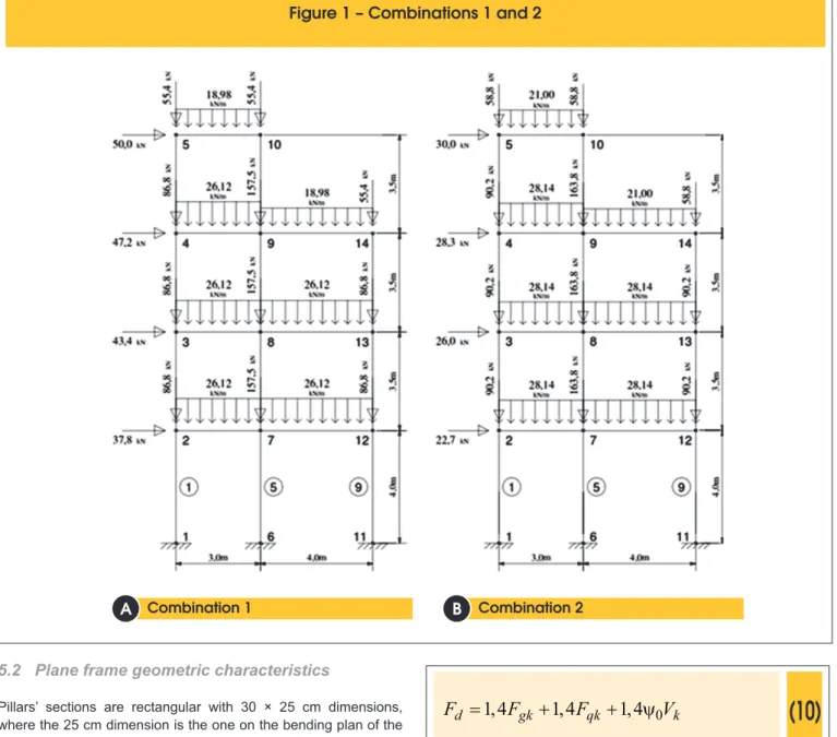
In this article, there were carried out numerical studies of qualitative character, as it intends to investigate the relations among studied variables accurately. It is used a plane frame with 14 nodes and 18 bars, Figure 1. The study consists of numerical analysis, which were performed by programming (script) in MatLab1 and Mix System2.
For the actions wind forces were considered, as well as the forces resulted from the structural elements’ weight and using loads’ (ac-cidental loads).
In the analysis with
α
parameter, only actions due to wind were used, with the characteristic values, in order to determine the maxi-mum structure displacement. With the sum of these loads, it was possible to obtain an equivalent distributed load which cause the same displacement at the top in a ictitious column. Thus,E I
c cvalue was obtained, which is an equivalent value.
Numerical analysis of 2nd order efects (nonlinear geometric
analysis) were made with Mix System, using secant matrix given by equation (5). The 2nd order analysis’ results were taken as a
reference to comparison with the approximate procedure.
5.1 Materials’ physical characteristics
For the frame, it was used concrete with compressive strength char-acteristic
f
ck=
30
MPa
. Secant stifness of structural elements istreated diferently for beams and columns, so that, in a simpliied form, the nonlinearity of the materials can be considered, a result of nonlinear relations between stress and deformation and of rein-forced concrete behavior. This procedure, which is consistent with NBR 6118 [2], consists in reducing the stifness values of each struc-tural element type. Thus, for beams with diferent compression and tension reinforcement and pillars, it is used value given by equations
(7) and (8), respectively. In which
I
c is the moment of inertia of the gross concrete section andα
E=
1
(granite and gneiss).(6)
5600
ci E ck
E
=
a
f
(7)
( )
EI
SEC=
0,4
E I
ci c(8)
497 IBRACON Structures and Materials Journal • 2016 • vol. 9 • nº 4
5.2 Plane frame geometric characteristics
Pillars’ sections are rectangular with 30 × 25 cm dimensions, where the 25 cm dimension is the one on the bending plan of the plane frame. To simulate rigid diaphragm efect, the beams (cross-section of 15 × 40 cm) are simulated with cross-(cross-sectional area of
5 2
6 10
×
cm
, ictitious increase, trick that enables to obtain equalhorizontal displacements along pavement points.
5.3 Actions
In this paper, were used permanent and accidental loads. In the analysis, were used two loads’ combinations for ultimate limit state. The irst load case considers the wind as main accidental action, equation (9) where
ψ
0=
0, 7
(commercial buildings). Thesecond case considers wind action as a secondary accidental ac-tion, equation (10), with
ψ
0=
0, 6
. In these equations, “g” indexrefers to permanent loads, “q” to vertical accidental loads, “V” to wind action (horizontal loads) and “k” to characteristic values of each action. Combinations used in the approximate procedure are presented in equations (11) and (12).
(9)
0
1,4
1,4
1,4
=
+
+
d gk k qk
F
F
V
y
F
(10)
0
1,4
1,4
1,4
=
+
+
d gk qk k
F
F
F
y
V
(11)
0
1,4
1,4
1,4
=
+
z+
d gk k qk
F
F
g
V
y
F
(12)
01,4
1,4
1,4
=
+
+
zd gk qk k
F
F
F
g
y
V
Figure 1 shows used values in each combination (inal values). For the approximate procedure, it was used MatLab script, where only wind actions on Figure 1 (a) and Figure 1 (b) are multiplied by
g
z coeicient.Combination 1 Combination 2
B
B
498 IBRACON Structures and Materials Journal • 2016 • vol. 9 • nº 4
6. Results and discussions
6.1 Alpha and Gamma-Z (a,
g
z)
For
α
coeicient, it was obtained0, 64
and in accordance with NBR 6118 [2], 2nd order efects must be considered, because1
α α
>
.Regarding
g
z coeicient, two values were obtained, one for eachone of the actions’ combinations. For the irst combination, equa-tion (11), which has wind as main accidental action, the obtained value was
g
z=
1,10
. For the second combination, equation (12), with vertical load as main accidental action, the obtained value was1,11
z
g
=
. NBR 6118 [2] recommends that 2nd order efects mustbe considered if
g
z>
1,10
. Therefore, withα
parameter andg
zcoeicient is possible to verify that it is necessary to consider 2nd
order efects. The next section deals with this subject.
6.2 Second order analysis
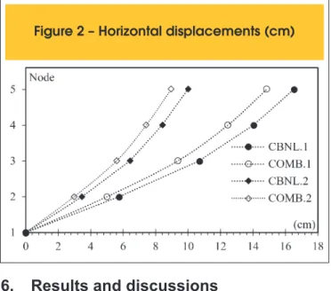
Figure 2 shows results of horizontal displacements of nodes 1 to 5,
for 1st order analysis, COMB.1 equation (9) and COMB.2 equation (10), and nonlinear analysis (2nd order) arising out of the two
previ-ous combinations, and CBNL.1 CBNL.2, respectively.
It is found that the larger displacement amplitudes are obtained from combination 1, which uses equation (9), which has wind action as main accidental. However, to the same combination, COMB.1, there was obtained the lowest value to
g
z coeicient.This is because 2nd order efects are due to the product of vertical
loads by respective horizontal displacements. While in COMB.1 it was veriied the greatest horizontal displacements, COMB.2 has the largest vertical loads and greater 2nd order efect, in this case.
Displacements’ diference between 1st and 2nd order analysis, for
each of the combinations, is featured in Figure 3.
It is veriied that to the node 5 (top of the frame), with the irst ac-tions’ combination there is an increase in displacements of 11,26%, when performing 2nd order efects analyses. For the second
combi-nation, the increase was 11,66%. In both cases, the biggest difer-ence is obtained for node 2, with maximum value of 16,29% in the second combination.
Bending moments at pillars’ base (bars 1, 5 and 9), obtained for all combinations (1st and 2nd order) are presented in Figure 4 and
Figure 5. In Figure 4, wind action is the main accidental action, and Figure 5 has wind action as a secondary accidental action. In both igures, it is noted that the portion due only to 2nd order
eforts is greater than 10% in all pillars and combinations (right vertical axis in the igures), in which “
[
2ª /1ª
]
−
1
” represents the diference in percentage of geometric nonlinear analysis (2nd)over linear analysis (1st).
Figure 2 – Horizontal displacements (cm)
Figure 3 – Horizontal displacements,
difference (%)
st nd
499 IBRACON Structures and Materials Journal • 2016 • vol. 9 • nº 4
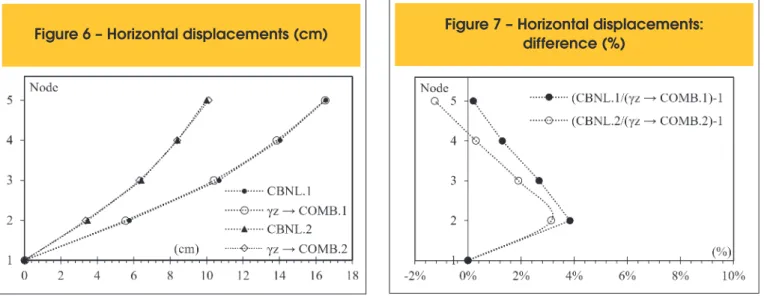
6.3 Approximate procedure (simpliied)
To diferentiate the results, at the igures’ legend, results obtained by simpliied or approximate analysis (described in 4.2) are indi-cated by “
g
z” and results obtained by nonlinear geometric analysisare indicated by “ 2ª ”.
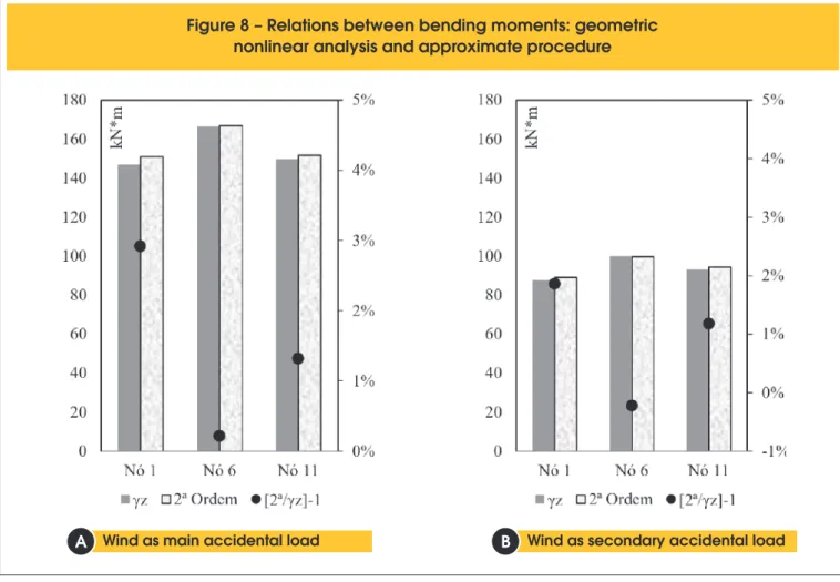
Results of horizontal displacement from nodes 1, 2, 3, 4 and 5 are presented in Figure 6 and the diference between the two procedures is reported in Figure 7. Bending moment values at the pillars’ base, with their respective comparing results, are featured in Figure 8.
These results prove that approximate procedure achieved an ex-cellent performance compared to reined method, which uses geo-metric stifness matrix. In Table 1 and Table 2, it is possible to better visualize the diference between procedures for displacements and bending moments, respectively. It is noted that for displacements at the top of the frame (node 5), relative diference is only 0,18% for combination 1, and only -1,25% for combination 2, and in the latter case, approximate procedure is in favor of safety.
7. Conclusion
The study presented in this article reports the importance of check-ing 2nd order efects in order to guarantee the structure’s safety.
Figure 5 – Relations between bending moments
st nd
in 1 and 2 order analysis: Combination 2
Figure 6 – Horizontal displacements (cm)
!" #$! %&#'difference (%)
Table 1 – Horizontal displacements (cm)
Node dif = CNBL.1 - 1
gz COMB.1 dif =
CNBL.2 - 1 gz COMB.2
1 0 0
2 3,79% 3,14%
3 2,69% 1,90%
4 1,30% 0,30%
5 0,18% -1,25%
Table 2 – Bending moment at pillars’ base
(kN·m)
Node dif = CNBL.1 - 1
gz COMB.1 dif =
CNBL.2 - 1 gz COMB.2
1 2,92% 1,86%
6 0,22% -0,22%
500 IBRACON Structures and Materials Journal • 2016 • vol. 9 • nº 4 It was found that the
α
parameter and theg
z coeicient wereefective to demonstrate the need of evaluation of these efects. Geometric nonlinear analysis, using geometric stifness matrix, was satisfactory to obtain eforts and displacements due to 2nd
or-der efects. These efects have shown to be greater than 10% of the 1st order efects. Fact that the simpliied procedures
α
and
g
zalready indicated.
The approximate procedure, which consists in multiplying hori-zontal forces by the
g
z coefficient, proved to be suitable toobtain the desired 2nd order effects of the studied plane frame,
both to the displacements and bending moments. It was found that the approximate procedure application is simple and does not require advanced knowledge on nonlinear geometric analysis, as it is required in the refined method. However, the results are valid to structural characteristics simulated in this article and this verification should not be extrapolated for other structures.
8. Acknowledgements
The authors thank Federal University of Santa Catarina (UFSC), Analysis and Design of Structures Group (GAP-UFSC), Postgradu-ate Program in Civil Engineering (PPGEC-UFSC) and the Federal Technological University of Paraná (UTFPR).
9. References
[1] ELLWANGER, R. J. Inluência do número de pavimentos no parâmetro de instabilidade de edifícios contraventados por paredes ou núcleos de concreto armado. RIEM - Revista IBRACON de Estruturas e Materiais, v.6, n.1, 2013; p.783– 810.
[2] ASSOCIAÇÃO BRASILEIRA DE NORMAS TÉCNICAS. Projeto de estruturas de concreto - Procedimento. NBR 6118, Rio de Janeiro, 2014.
[3] Silva, A. R. D. da; Prado, Í. M.; Silveira, R. A. da M. CS-ASA: a new computational tool for advanced analysis of steel frames. Revista Escola de Minas, v.66, n.3, 2013; p.281–288.
[4] Schimizze, A. M. Comparison of P-Delta Analyses of Plane Frames Using Commercial Structural Analysis Programs
and Current Aisc Design Speciications, Blacksburg, 2001, Thesis (master degree), Faculty of the Virginia Polytechnic Institute and State University, 150 p.
[5] Moncayo, W. J. Z. Análise de segunda ordem global em ed-ifícios com estrutura de concreto armado, São Carlos, 2011, Dissertação (mestrado) - Escola de Engenharia de São Car-los, Universidade de São Paulo, 221 p.
[6] Greco, M.; Gesualdo, F. A. R.; Venturini, W. S.; Coda, H. B. Nonlinear positional formulation for space truss analysis.
Figure 8 – Relations between bending moments: geometric
nonlinear analysis and approximate procedure
Wind as main accidental load Wind as secondary accidental load
B
B
501 IBRACON Structures and Materials Journal • 2016 • vol. 9 • nº 4
Finite Elements in Analysis and Design, v.42, n.12, 2006; p.1079–1086.
[7] Greco, M.; Coda, H. B. Positional FEM formulation for lex-ible multi-body dynamic analysis. Journal of Sound and Vi-bration, v.290, n.3-5, 2006; p.1141–1174.
[8] Coda, H. B ; Greco, M. A simple FEM formulation for large delection 2D frame analysis based on position description. Computer Methods in Applied Mechanics and Engineering, v.193, n.33-35, 2004; p.3541–3557.
[9] Banki, A. L. Estudo sobre a inclusão da não linearidade geo-métrica em projetos de edifícios, FLorianópolis, 1999, Disser-tação (mestrado) - Programa de Pós-Graduação em Engen-haria Civil, Universidade Federal de Santa Catarina, 376 p. [10] Oliveira, D. M.; Silva, N. A.; Oliveira, P. M.; Ribeiro, C. C.
Evaluation of second order moments in reinforced concrete structures using the γz and B2 coeicients. RIEM - Revista IBRACON de Estruturas e Materiais, v.7, n.3, 2014; p.329–348. [11] Junior, E. P.; Nogueira, G. V.; Neto, M. M.; Moreira, L.
S. Material and geometric nonlinear analysis of reinforced concrete frames. RIEM - Revista IBRACON de Estruturas e Materiais, v.7, n.5, 2014; p.879–904.
[12] Carmo, R. M. S. Efeitos de segunda ordem em edifícios usuais de concreto armado, São Carlos, 1995, Dissertação (mestrado) - Escola de Engenharia de São Carlos, Universi-dade de São Paulo, 135 p.
[13] Vasconcelos, A. C. Em que casos não se deve aplicar o
processo simpliicado do Gamaz para determinação dos
efeitos de 2a ordem?
http://www.tqs.com.br/suporte-e-ser- vicos/biblioteca-digital-tqs/89-artigos/175-em-que-casos- nao-se-deve-aplicar-o-processo-simplificado-do-gamaz-para-determinacao-dos-efeitos-de-2o-ordem. - acesso em 2015-02-16.
[14] CHEN, W.F. ; LUI, E.M. Stability design of steel frames. Boca Raton, Flórida, CRC Press, 1991.
[15] Gelatti, F. Análise não linear física e geométrica de pórti-cos planos de concreto armado modelagem por elementos
initos de barra, Florianópolis, 2012, Dissertação (mestrado) - Programa de Pós-Graduação em Engenharia Civil, Univer-sidade Federal de Santa Catarina, 241 p.
[16] Medeiros, S. P. Módulo TQS para Análise Não-Linear
Geométrica de Pórticos Espaciais. http://www.tqs.com.br/ suporte-e-servicos/biblioteca-digital-tqs/89-artigos/268- modulo-tqs-para-analise-nao-linear-geometrica-de-porticos-espaciais. - acesso em 2015-02-16.