M. Papadrakakis, M. Fragiadakis, V. Plevris (eds.) Corfu, Greece, 26–28 May 2011
BLIND PREDICTION OF A FULL-SCALE RC BRIDGE COLUMN
TESTED UNDER DYNAMIC CONDITIONS
Federica Bianchi1, Romain Sousa1 and Rui Pinho2
1 European Centre for Training and Research in Earthquake Engineering (Eucentre)
Via Ferrata 1, 27100 Pavia, Italy
e-mail: {federica.bianchi, romain.sousa}@eucentre.it
2 Department of Structural Mechanics, University of Pavia
Via Ferrata 1, 27100 Pavia, Italy e-mail: [email protected]
Keywords: RC bridge column, Blind Prediction, Fiber Element, Dynamic non-linear analysis, Shaking Table.
Abstract. The definition of appropriate modelling approaches combined with a consistent
software framework is a topic of major importance in the present days for structural engi-neering in general and, particularly, for earthquake engiengi-neering. The accuracy of the results obtained in the recent “Concrete Column Blind Prediction Contest 2010” for a full-scale re-inforced concrete bridge column tested on the NEES Large High-Performance Outdoor Shake Table, seems to indicate that current modelling strategies are on the right track. The 1.2 m diameter cantilevered column spans 7.2 m from the footing. A massive 230 tonne reinforced concrete block supported by the column generates the inertial forces to mobilize the column capacity. Seismic performance was investigated under 6 ground motions, starting with low-intensity shaking and bringing the column progressively to near-collapse conditions. Based on the obtained results from the pre-contest simulation, as well with the post-contest analysis, it was possible to extract some important conclusions regarding the application of several strategies, namely the use of different type elements, element discretization, constitutive laws for materials.
1 INTRODUCTION
In 2010 a blind prediction contest was announced and sponsored by PEER and NEES. The aim of the contest was to predict failure mode and several response quantities for a full-scale reinforced concrete bridge column. The specimen, subjected to six uniaxial earthquake ground motions, was tested in September 2010 on the NEES Large High-Performance Outdoor Shake Table located at UCSD’s Englekirk Structural Engineering Center, starting with low-intensity shaking and bringing the column progressively to near-collapse conditions.
In order to prepare the analytical model, the organizing committee provided all the relevant input data, such as construction details, material properties and base excitation records. Based on the obtained informations, the FE model of the bridge column was prepared using a fiber-based Finite Elements computer program. Several modelling strategies (e.g. different type el-ements, element discretization, constitutive laws for materials, damping, etc.) were studied in order to obtain the best representation of the real structure. A nonlinear dynamic time-history analysis was performed for predicting the failure mode of the structure. Because the actual loadings were determined during the course of the testing, after the pre-test the organizing committee provided each participant with the registered records. The analytical model was thus updated and another nonlinear dynamic time-history analysis was carried out considering the actual loading.
The analytical results, in terms of displacements at the top of the column and base shear, were compared with experimental ones to assess the nonlinear response prediction capabilities of the adopted modelling strategy.
2 DESCRIPTION OF THE SPECIMEN
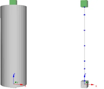
The test specimen is a full-scale RC bridge column (see Figure 1) [1] which details are consistent with current Caltrans design practice. The 1.2 m diameter cantilevered column spans 7.2 m from the footing, as shown in Figure 2. A massive 230 tonne reinforced concrete block supported by the column generates the inertial forces to mobilize the column capacity.
Figure 1: Full-scale reinforced concrete bridge column tested on the NEES Large High-Performance Outdoor Shake Table at UCSD’s Englekirk Structural Engineering Center [1].
Figure 2: RC bridge column specimen configuration [1].
The concrete used for the construction of the column was normal-weight with a cylinder compressive strength of 41500 kPa.
The reinforcement of the column consisted of eighteen No. 11 continuous bars (see Figure 3), as longitudinal reinforcement and butt-welded No. 5 double hoops, spaced at 152-mm on-center (see Figure 3), as transverse reinforcement. The steel was A706 grade 60 for both lon-gitudinal and transverse reinforcement.
Figure 3: Reinforcement details for the RC bridge column [1].
3 FINITE ELEMENTS MODELLING OF THE RC BRIDGE COLUMN 3.1 Selection of the Finite Elements computer program
The software employed in this work for modelling the behavior of the RC bridge column is SeismoStruct [2], a fiber-based Finite Elements computer program for seismic analysis of framed structures, which is freely downloadable from the Internet. The program is capable of predicting the dynamic behavior of any framed type of structural configuration, accounting both for geometric nonlinearities and material inelasticity.
In the following paragraphs, a description of the constitutive laws for materials, type ele-ments and element discretization is given.
3.2 Section and materials
In the model, the column cross-section was defined through a 1.22 m diameter reinforced concrete circular section with a concrete cover of 0.06667 m and the longitudinal reinforce-ment which reproduces the layout of the test specimen, as shown in Figure 3.
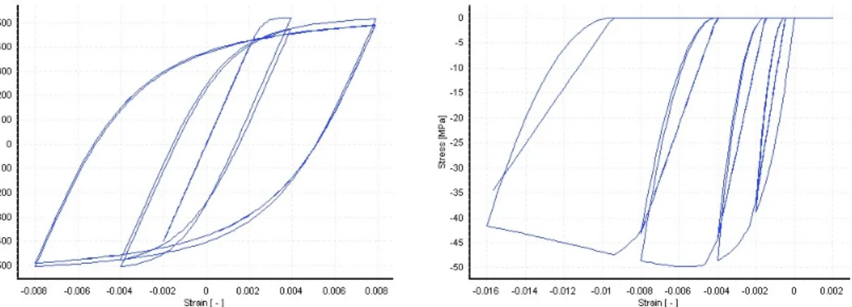
The stress-strain behavior of the reinforcing steel (see Figure 4(left)) was described by the nonlinear model of Menegotto and Pinto [3], as modified by Filippou et al. [4] including iso-tropic strain hardening effects.
The constitutive law employed for defining the concrete material is a nonlinear constant confinement concrete model that follows the relationship proposed by Mander et al. [5], later modified by Martinez-Rueda and Elnashai [6] for numerical stability reasons under large dis-placements/deformations (see Figure 4(right)). This is a uniaxial model in which a constant confining pressure is assumed through the entire stress-strain range.
Figure 4: Menegotto-Pinto steel model, with Filippou isotropic hardening (left) and nonlinear constant
confine-ment concrete model (with kc = 1.2) (right).
Some mechanical characteristics of the materials, such as yield strength, ultimate stress and strain for the steel, cylinder compressive strength and strain at peak stress for the concrete, were provided by the organizing committee. The other model parameters were calibrated and set as shown in Table 1 and 2.
Parameter Steel
Modulus of elasticity (kPa) 2.00E+008
Yield strength (kPa) 518500
Strain hardening parameter 0.008
Transition curve initial shape parameter (default value) 20 1st transition curve shape coefficient (default value) 18.5 2nd transition curve shape coefficient (default value) 0.15
1st isotropic hardening coefficient 0
2nd isotropic hardening coefficient 1
Specific weight (kN/m3) 77
Table 1: Parameters for Menegotto-Pinto steel model.
Parameter Concrete (conf) Concrete (unconf)
Cylinder compressive strength (kPa) 41500 41500
Tensile strength (kPa) 0 0
Strain at unconfined peak stress (m/m) 0.0028 0.0028
Constant confinement factor 1.2 1
Specific weight (kN/m3) 23.6 23.6
The tensile strength of the concrete was ignored for the numerical stability of the analysis. 3.3 Element type and discretization
Two different FE formulations can be selected within the software for implementing dis-tributed inelasticity frame elements, the classical displacement-based (DB) formulation (e.g. Hellesland and Scordelis [7], Mari and Scordelis [8]) and the more recent force-based formu-lation (e.g. Spacone et al. [9], Neuenhofer and Filippou [10]).
In the present study, a 3D inelastic beam-column element with displacement-based (DB) formulation and capable of capturing both geometric and material nonlinearities was selected for modelling the cantilevered column. The number of fibers used in section equilibrium computations was set to 300, in order to guarantee an adequate reproduction of the stress-strain distribution across the element cross-section, considering the shape and material charac-teristics of the latter and the degree of material inelasticity that is likely to be reached.
The structural member was appropriately subdivided into eight elements of different length (see Figure 5), in order to accept the assumption of a linear curvature field inside each of the sub-domains.
3.4 Applied mass and boundary conditions
In order to perform the nonlinear dynamic time-history analysis required for the blind pre-diction, it was necessary to define the mass elements. The mass of the column was automati-cally computed by the program knowing the material’s self weights, while the additional mass coming from the reinforced concrete block supported by the column, was applied in a lumped fashion at the top node (see Figure 5). The applied values are summarized in Table 3.
Lumped mass Concrete block
Translational mass (tonne) 228
Rotational mass (tonne × m2) 885
Table 3: Computed masses.
Modelling of the footing under the column was ignored; hence the column base node was considered as fully restrained against rotations and translations (see Figure 5).
3.5 Applied dynamic loading
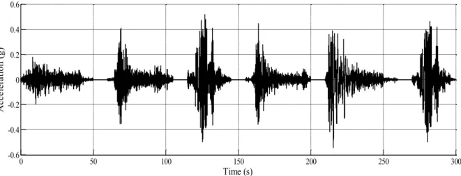
For post-test response prediction, the actual ground motions were applied as dynamic load-ing. Time history analysis was carried out for a single input record consisting of an assem-blage of the six accelerograms provided by the organizing committee. Ten seconds of delay were left between one motion and the one immediately after (see Figure 6) in order to damp out the structure motion.
0 50 100 150 200 250 300 -0.6 -0.4 -0.2 0 0.2 0.4 0.6 Time (s) A cc el er at ion (g)
Figure 6: Actual acceleration records.
The time step for the dynamic analysis was set as 0.00390625 s, coincident with the input record sampling time step.
3.6 Damping, Integration Algorithm and Convergence Criterion
In addition to the hysteretic damping, which was implicitly accounted for by the cyclic ma-terial relationships, a small amount of non-hysteretic equivalent viscous damping (1%) was also introduced in order to improve the numerical stability of the dynamic nonlinear analyses. A tangent stiffness-proportional viscous damping model was employed, as suggested by Priestley and Grant [11] and Hall [12].
Regarding the numerical integration scheme, the Hilber-Hughes-Taylor algorithm (Hilber
et al. [13]), with an alpha coefficient equal to -0.1, was adopted.
Finally, the displacement/rotation based scheme was selected as convergence criterion. 4 COMPARISON BETWEEN NUMERICAL AND EXPERIMENTAL RESULTS
After the submission of the post-test analytical results, the organizing committee provided all the responses of the column, in terms of maximum/minimum values and time histories, for each ground motion.
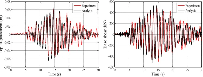
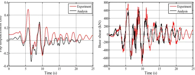
The experimental time histories of column top displacement and base shear were compared with the numerical ones; they are presented in the following figures. It is observed that the numerical predictions matched relatively well the experimental results. In particular, there is a good agreement between both the amplitude and the frequency content of the response when the column is subjected to earthquake 1, 3, 5 and 6 (see Figures 7, 8, 9 and 10, respectively).
0 5 10 15 20 25 30 -0.08 -0.06 -0.04 -0.02 0 0.02 0.04 0.06 0.08 Time (s) T op di spl ac em ent ( m ) Experiment Analysis 0 5 10 15 20 25 30 -600 -400 -200 0 200 400 600 Time (s) B as e she ar ( kN ) Experiment Analysis
Figure 7: Top displacements (left) and base shear during earthquake 1
0 5 10 15 20 25 30 -0.4 -0.3 -0.2 -0.1 0 0.1 0.2 0.3 Time (s) T op di spl ac em ent ( m ) Experiment Analysis 0 5 10 15 20 25 30 -1000 -500 0 500 1000 Time (s) B as e she ar ( kN ) Experiment Analysis
Figure 8: Top displacements (left) and base shear during earthquake 3
0 5 10 15 20 25 -0.2 0 0.2 0.4 0.6 Time (s) T op di spl ac em ent ( m ) Experiment Analysis 0 5 10 15 20 25 -500 0 500 1000 Time (s) B as e she ar ( kN ) Experiment Analysis
0 5 10 15 20 25 -0.4 -0.2 0 0.2 0.4 0.6 Time (s) T op di spl ac em ent ( m ) Experiment Analysis 0 5 10 15 20 25 -800 -600 -400 -200 0 200 400 600 800 Time (s) B as e she ar ( kN ) Experiment Analysis
Figure 10: Top displacements (left) and base shear during earthquake 6 5 CONCLUSIONS
This work described the blind prediction of the dynamic response of a full-scale RC bridge column tested on the NEES Large High-Performance Outdoor Shake Table located at UCSD’s Englekirk Structural Engineering Center. The results show that the definition of ap-propriate modelling approaches combined with a consistent software framework led to a rela-tively accurate prediction of the global nonlinear dynamic response of the column.
REFERENCES
[1] NEES@UCSD, Concrete Column Blind Prediction Contest. Available from: http://nisee2.berkeley.edu/peer/prediction_contest [2010].
[2] SeismoSoft, SeismoStruct – A Computer Program for Static and Dynamic nonlinear
analysis of framed structures. Available from: http://www.seismosoft.com [2008].
[3] M. Menegotto, P.E. Pinto, Method of analysis for cyclically loaded R.C. plane frames including changes in geometry and non-elastic behaviour of elements under combined normal force and bending. Symposium on the Resistance and Ultimate Deformability of
Structures Acted on by Well Defined Repeated Loads, International Association for
Bridge and Structural Engineering, Zurich, Switzerland, pp. 15-22, 1973.
[4] F.C. Filippou, E.P. Popov, V.V Bertero, Modelling of R/C joints under cyclic excita-tions. ASCE Journal of Structural Engineering, Vol. 109, No. 11, pp. 2666-2684, 1983. [5] J.B Mander, M.J.N. Priestley, R. Park, Theoretical stress-strain model for confined
con-crete. Journal of Structural Engineering, Vol. 114, No. 8, pp. 1804-1826, 1988.
[6] J.E. Martinez-Rueda, A.S. Elnashai, Confined concrete model under cyclic load.
Mate-rials and Structures, Vol. 30, No. 197, pp. 139-147, 1997.
[7] J. Hellesland, A. Scordelis, Analysis of RC bridge columns under imposed deformations.
IABSE Colloquium, Delft, pp. 545-559, 1981.
[8] A. Mari, A. Scordelis, Nonlinear geometric material and time dependent analysis of three dimensional reinforced and prestressed concrete frames. SESM Report 82-12, De-partment of Civil Engineering, University of California, Berkeley, 1984.
[9] E. Spacone, V. Ciampi, F.C. Filippou, Mixed formulation of nonlinear beam finite ele-ment. Computers & Structures, Vol. 58, No. 1, pp. 71-83, 1996.
[10] A. Neuenhofer, F.C. Filippou, Evaluation of nonlinear frame finite-element models.
Journal of Structural Engineering, Vol. 123, No. 7, pp. 958-966, 1997.
[11] M.J.N. Priestley, D.N. Grant, Viscous damping in seismic design and analysis. Journal
of Earthquake Engineering, Vol. 9, Special Issue 1, pp. 229-255, 2005.
[12] J.F. Hall, Problems encountered from the use (or misuse) of Rayleigh damping.
Earth-quake Engineering and Structural Dynamics, Vol. 35, No. 5, pp. 525-545, 2006.
[13] H.M. Hilber, T.J.R. Hughes, R.L. Taylor, Improved numerical dissipation for the time integration algorithms in structural dynamics. Earthquake Engineering and Structural
![Figure 1: Full-scale reinforced concrete bridge column tested on the NEES Large High-Performance Outdoor Shake Table at UCSD’s Englekirk Structural Engineering Center [1]](https://thumb-eu.123doks.com/thumbv2/123dok_br/18381735.892495/2.892.141.754.708.1052/figure-reinforced-concrete-performance-outdoor-englekirk-structural-engineering.webp)
![Figure 2: RC bridge column specimen configuration [1].](https://thumb-eu.123doks.com/thumbv2/123dok_br/18381735.892495/3.892.240.651.125.469/figure-rc-bridge-column-specimen-configuration.webp)